EP0251833B1 - Einrichtung zur zeitweisen Einlagerung von flachen Gegenständen - Google Patents
Einrichtung zur zeitweisen Einlagerung von flachen Gegenständen Download PDFInfo
- Publication number
- EP0251833B1 EP0251833B1 EP87401144A EP87401144A EP0251833B1 EP 0251833 B1 EP0251833 B1 EP 0251833B1 EP 87401144 A EP87401144 A EP 87401144A EP 87401144 A EP87401144 A EP 87401144A EP 0251833 B1 EP0251833 B1 EP 0251833B1
- Authority
- EP
- European Patent Office
- Prior art keywords
- article
- pulse
- track
- shaft
- Prior art date
- Legal status (The legal status is an assumption and is not a legal conclusion. Google has not performed a legal analysis and makes no representation as to the accuracy of the status listed.)
- Expired - Lifetime
Links
Images


Classifications
-
- B—PERFORMING OPERATIONS; TRANSPORTING
- B65—CONVEYING; PACKING; STORING; HANDLING THIN OR FILAMENTARY MATERIAL
- B65H—HANDLING THIN OR FILAMENTARY MATERIAL, e.g. SHEETS, WEBS, CABLES
- B65H29/00—Delivering or advancing articles from machines; Advancing articles to or into piles
- B65H29/12—Delivering or advancing articles from machines; Advancing articles to or into piles by means of the nip between two, or between two sets of, moving tapes or bands or rollers
-
- G—PHYSICS
- G06—COMPUTING; CALCULATING OR COUNTING
- G06K—GRAPHICAL DATA READING; PRESENTATION OF DATA; RECORD CARRIERS; HANDLING RECORD CARRIERS
- G06K13/00—Conveying record carriers from one station to another, e.g. from stack to punching mechanism
- G06K13/02—Conveying record carriers from one station to another, e.g. from stack to punching mechanism the record carrier having longitudinal dimension comparable with transverse dimension, e.g. punched card
- G06K13/04—Details, e.g. flaps in card-sorting apparatus
-
- G—PHYSICS
- G06—COMPUTING; CALCULATING OR COUNTING
- G06K—GRAPHICAL DATA READING; PRESENTATION OF DATA; RECORD CARRIERS; HANDLING RECORD CARRIERS
- G06K13/00—Conveying record carriers from one station to another, e.g. from stack to punching mechanism
- G06K13/02—Conveying record carriers from one station to another, e.g. from stack to punching mechanism the record carrier having longitudinal dimension comparable with transverse dimension, e.g. punched card
- G06K13/08—Feeding or discharging cards
-
- B—PERFORMING OPERATIONS; TRANSPORTING
- B65—CONVEYING; PACKING; STORING; HANDLING THIN OR FILAMENTARY MATERIAL
- B65H—HANDLING THIN OR FILAMENTARY MATERIAL, e.g. SHEETS, WEBS, CABLES
- B65H2301/00—Handling processes for sheets or webs
- B65H2301/30—Orientation, displacement, position of the handled material
- B65H2301/33—Modifying, selecting, changing orientation
- B65H2301/333—Inverting
-
- B—PERFORMING OPERATIONS; TRANSPORTING
- B65—CONVEYING; PACKING; STORING; HANDLING THIN OR FILAMENTARY MATERIAL
- B65H—HANDLING THIN OR FILAMENTARY MATERIAL, e.g. SHEETS, WEBS, CABLES
- B65H2701/00—Handled material; Storage means
- B65H2701/10—Handled articles or webs
- B65H2701/19—Specific article or web
- B65H2701/1912—Banknotes, bills and cheques or the like
-
- B—PERFORMING OPERATIONS; TRANSPORTING
- B65—CONVEYING; PACKING; STORING; HANDLING THIN OR FILAMENTARY MATERIAL
- B65H—HANDLING THIN OR FILAMENTARY MATERIAL, e.g. SHEETS, WEBS, CABLES
- B65H2701/00—Handled material; Storage means
- B65H2701/10—Handled articles or webs
- B65H2701/19—Specific article or web
- B65H2701/1914—Cards, e.g. telephone, credit and identity cards
-
- B—PERFORMING OPERATIONS; TRANSPORTING
- B65—CONVEYING; PACKING; STORING; HANDLING THIN OR FILAMENTARY MATERIAL
- B65H—HANDLING THIN OR FILAMENTARY MATERIAL, e.g. SHEETS, WEBS, CABLES
- B65H2701/00—Handled material; Storage means
- B65H2701/10—Handled articles or webs
- B65H2701/19—Specific article or web
- B65H2701/1916—Envelopes and articles of mail
-
- Y—GENERAL TAGGING OF NEW TECHNOLOGICAL DEVELOPMENTS; GENERAL TAGGING OF CROSS-SECTIONAL TECHNOLOGIES SPANNING OVER SEVERAL SECTIONS OF THE IPC; TECHNICAL SUBJECTS COVERED BY FORMER USPC CROSS-REFERENCE ART COLLECTIONS [XRACs] AND DIGESTS
- Y10—TECHNICAL SUBJECTS COVERED BY FORMER USPC
- Y10S—TECHNICAL SUBJECTS COVERED BY FORMER USPC CROSS-REFERENCE ART COLLECTIONS [XRACs] AND DIGESTS
- Y10S271/00—Sheet feeding or delivering
- Y10S271/902—Reverse direction of sheet movement
Definitions
- the present invention relates to a device for the temporary storage of flat articles, such as sheets of paper, checks, cards, letters or similar documents.
- Equipment for treating flat articles has been known for a long time, in which the articles to be treated are introduced one by one at the entrance to a transport path generally constituted by endless belts or rotary drive rollers, and are routed to the exit of this transport route, passing successively through at least two article processing devices.
- a transport path generally constituted by endless belts or rotary drive rollers
- the two processing devices operate at different processing speeds, so that, if the work which is carried out by the processing device placed upstream is accomplished in a shorter time than that which is carried out by the other processing device, an article, driven continuously by the transport route, can very well appear at the entrance of this other device when it has not yet finished processing the previous article.
- the articles to be sorted which are introduced at the entrance of a first advancement track are conveyed by this track and introduced into the storage device where they are then stopped by the wall against which they abut.
- the articles which are immobilized in this storage device are then extracted one by one from this device in the opposite direction to that which they had at the time of their introduction into this device, and are then engaged at the entry of a second progress track which routes them to the receiving station responsible for sorting.
- a storage device of this kind can naturally be used in the article processing equipment which has been mentioned above and which comprise at least two article processing devices, as well as in the equipment which comprises only one processing device, but in which the transport path is arranged so as to allow an article to pass twice through this unique processing device.
- the extraction mechanism with which they are provided comprises a single endless friction belt, which, depending on the surface condition of the articles, has an insufficient coefficient of friction to ensure the dragging of the articles without slipping. placed in contact with it. It can happen that these articles are checked out from the storage device with a certain delay which varies from one article to another, or even that they are not checked out at all.
- this drawback does not appear because the extraction mechanism consists of a pneumatic suction device.
- this latter device does not give all the desirable satisfaction that, in order to obtain correct training of the arti keys, it is necessary to adjust the value of the depression according to the mass and the rigidity presented by these articles, which makes this adjustment particularly delicate.
- a storage device which has been described in patent FR-A 1 489 729 and which comprises a storage pocket and an extraction mechanism consisting, on the one hand of '' an adhesion drive roller mounted at one end of a first arm, and on the other hand an applicator member in the form of a friction roller mounted at one end of a second arm, this roller drive and this applicator member being arranged on either side of the storage bag.
- the two arms of this extraction mechanism are each articulated around an axis and are controlled by an electromagnet. As long as this electromagnet is not energized, these two arms occupy a first position, called the rest position, in which the drive roller and the applicator member are slightly separated from one another, so as to be outside the storage pocket.
- the present invention precisely overcomes the disadvantages of the prior art and provides an article storage device which not only is capable of storing more than one article at a time, but then allows these articles to be extracted one by one, without sliding, that is to say at precise predetermined times.
- the invention relates to a device for the temporary storage of flat articles, such as sheets, comprising a storage pocket placed opposite the exit from a first track for advancing articles and the entry a second track for advancing articles, an adhesion drive member contiguous to this pocket and established to allow an article stored in this pocket to be brought into contact with this member, this member being designed to, when ordered, extract from the pocket an article which has been applied against it and engage this article in the second track, this device being characterized in that it further comprises an applicator member established for, in the absence of article in said pocket, occupy a rest position in which it is in contact with the drive member, without hampering the introduction into this pocket of articles advanced by the first track, and for, as soon as one has rticle is fully inserted into this pocket, make a full revolution, following a circular trajectory and in a predetermined direction, and thus return to this rest position to push this article and apply it against said drive member, this applicator member preventing then another article which then arrives in this pocket to come into contact with this
- Figure 1 shows a plan view of a flat article storage device which can be used in a wide variety of article processing machines, such as, for example, check processing machines, printing machines sheets of paper, letter-laughing machines, card-punch readers, or the like. It's for what, in the drawings accompanying this description, only the elements of the machine ensuring the transport of the articles intended to be temporarily contained in this storage device have been shown. It will be considered that, in the example described, these articles are constituted by sheets of paper.
- the machine which has been partially shown in Figures 1 and 2 comprises a rigid frame consisting of two vertical support plates 10 and 11 connected together by spacers 12 fixed to these two plates so as to constitute a non-deformable assembly.
- a storage device 13 which will be described a little later, is mounted inside this frame, this storage device being intended to temporarily contain sheets of paper delivered one by one at the outlet 14 of a first track advancement of sheets 15.
- this track 15, which has been shown partially in FIG. 1, comprises two guide plates 16 and 17 mounted between the support plates 10 and 11, a conveyor belt 18 tensioned on drive rollers of which only one, 19, has been shown in FIG.
- the drive roller 19 is integral with a shaft 21 which, supported by the support plates 10 and 11, can be driven in rotation, in the direction indicated by the arrow R, in a manner to be indicated later.
- FIG. 2 we deliberately omitted to represent these rollers as well as the transport belt 18, for obvious reasons of simplification.
- FIG. 1 shows that the drive shaft 23 is supported by the support plates 10 and 11 and that it is provided, at one of its ends, with a toothed wheel 25.
- a motor M1 is fixed on a plate 26 secured to the frame of the machine.
- the shaft 27 of this motor is provided with a pinion 28 which meshes with the toothed wheel 25.
- FIG. 2 makes it possible to understand that the shaft 21 of the drive roller 19 can be driven in rotation thanks to a mechanical connection comprising two pulleys 29 and 30 and a belt 31 stretched over these two pulleys, the pulley 29, disposed at the other end of the shaft 23, being coupled to this shaft 23 via a clutch WP, and the pulley 30 being fixed to one end of the shaft 21.
- This clutch WP is, in the example described, an electromagnetic clutch of known type. Consider here that this clutch is similar to that described incidentally in French Patent No.
- the diameters of the pulleys 29 and 30 are chosen such that a sheet engaging between the rollers 22A and 24A on the one hand and the rollers 22B and 24B on the other hand is driven by these at the same speed as that at which it was driven by the conveyor belt 18.
- the clutch WP is not excited, the shaft 21 is uncoupled from the shaft 23 which, alone, continues to be driven in rotation by the motor M1. Therefore, when a sheet, advanced by the conveyor belt 18, engages between the rollers 22A and 24A on the one hand and the rollers 22B and 24B on the other hand, this sheet continues to be driven by these rollers , even if at this time the WP clutch ceases to be energized.
- this sheet is deflected from its path by a deflecting blade 32 to be engaged between a drive roller 33 and a pressure roller 34. Since, as we will see more away, the drive roller 33 is continuously rotated, this sheet is introduced into a storage pocket 35 which, in the example described, is arranged obliquely to the advancement track 15, as shown Figure 1.
- This pocket 35 consists of a lower plate 36, an upper plate 37 and a stop plate 38 against which is applied the front edge of this sheet when the latter, released by the pebbles 33 and 34, falls inside this pocket.
- the plates 36, 37 and 38 are arranged between the support plates 10 and 11 and fixed to the latter in a known manner.
- the deflecting blade 32 and the pressure roller 34 have not been shown in order to better show the way in which the roller 33 is driven in rotation.
- the roller 33 is integral with a sleeve 40, itself threaded on an axis 41 supported by the support plates 10 and 11.
- the sleeve 10 is rotated around the axis 41 thanks to two pulleys 42 and 43 and to a belt 44 tensioned on these two pulleys, the pulley 42 being fixed on the drive shaft 23, while the other pulley 43 is fixed on this sleeve 40.
- the roller 33 is driven in rotation, continuously, by the motor M1, by through the shaft 23, the pulley 42, the belt 44, the pulley 43 and the sleeve 40.
- this sheet can be extracted from this pocket, in a manner which will be explained below, by means of two extraction rollers 45A and 45B which, as shown in the figure 2, are fixed on a shaft 46 supported by the support plates 10 and 11, each of these rollers being coated. on its outer surface, a layer of friction material such as, for example, synthetic rubber.
- the shaft 46 is provided, at one of its ends, with a toothed wheel 47.
- a motor M2 is fixed on a plate 48 secured to the frame of the machine.
- the shaft 49 of this motor is provided with a pinion 50 which meshes with the toothed wheel 47.
- Two pressure rollers 51 A and 51 B which will be discussed later, each cooperate respectively with each of the extraction rollers 45A and 45B in order to allow a sheet brought into engagement between these rollers, in a manner which will be described in the continuation of the text, to be extracted from the pocket 35 when the motor M2 is energized, this sheet then being engaged at the entrance 52 of a second track for advancing sheets 53.
- this second track 53 which comprises, in known manner, guide plates, such as 54, drive rollers, such as 55, associated with pressure rollers, such as 56, these drive rollers being rotated by a motor (not shown), in a direction such that a sheet engaged between one of these drive rollers and one of these pressure rollers is moved in a direction which, in FIG. 1, goes from the right towards the left.
- Each of the pressure rollers 51 A and 51 B is mounted idly on an articulation axis which, parallel to the axis 41 which was mentioned above, is fixed on an arm, respectively 57A and 57B, integral with this axis 41. It is thus understood that, if the axis 41 is journalled in the support plates 10 and 11, the two arms 57A and 57B and the two rollers 51 A and 51 B which they carry rotate around this axis 41 while passing in adequate recesses in the plates 36, 37 and 54. In Figure 1, the path followed by the roller 51 B during this movement has been indicated by a circular line C drawn in phantom. In FIGS.
- the two arms 57A and 57B and the two rollers 51A and 51 B are shown in a position, called a rest position, in which each of the two pressure rollers 51 A and 51 B is in contact, respectively, with each of the two extraction rollers 45A and 45B.
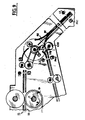
- the axis 41 can be rotated by the sleeve 40 by means of a one-turn clutch WT of the electromagnetic type, which has been shown in detail in FIG. 5. If we refer to this last figure, we see that the sleeve 40 , which is rotated continuously, is provided with a disc 100 having a notch 101 in which can engage, under the action of a spring 102, a pawl 103 articulated on a disc 104 fixed on the axis 41.
- This pawl 103 is normally retained out of engagement with this notch 101 by means of a hook 105 secured to the movable frame of an electromagnet EA, this hook 105 being held in engagement with the pawl 103, under the action of a spring 106 which tends to move this movable armature away from the excitation coil of this electromagnet.
- this coil When this coil is energized, the movable armature is attracted by this coil, tightens the spring 106 and releases the pawl 103 which, under the action of its spring 102, can engage in the notch 101 and drive the axis 41. The excitation of this coil ceases before this axis 41 has completed one revolution.
- the hook 105 returns to its initial position, so that the pawl 103, after having completed a rotation, is retained in passing by the hook 105 which releases it from the notch 101, thus causing the uncoupling of the sleeve 40 and the axis 41. So that, once uncoupled, the axis 41 is not rotated by the sleeve 40 due to the slight friction that this sleeve exerts on this axis, the axis 41 is provided, as as shown in FIG.
- the temporary storage device which has been shown in FIG. 1 also includes detection devices which make it possible to detect the passage of the sheets which, after having been advanced along the first track 15, are temporarily stored in the pocket 35 and are then extracted from this pocket to be driven along the second track 53.
- each of these detection devices is constituted by a photoelectric cell, such as PH3, which normally receives a light beam emitted by a light source , such as L3, and which generates, in response to the reception of this beam, an electric voltage at its output. This electric voltage disappears every time a sheet, engaging between the cell and the light source, comes to intercept this beam.
- the first (consisting of a PH3 cell and an L3 lamp) being placed near the exit 14 of the first track 15
- the second (consisting of a cell PH1 and a lamp L1) being installed in the part of the pocket 35 located near the stop plate 38
- the third (consisting of a PH2 cell and a lamp L2) being placed near the entry 52 of the second track 53.
- FIG. 3 the logic diagram of the circuits which are used to control the operation of the storage device which has been represented in FIGS. 1 and 2.
- this diagram includes an "OR" circuit U1, an inverter circuit 11 and three control circuits C1, C2 and C3, all of these circuits being of known type.
- each of these control circuits is analogous to those which have been incidentally described and represented in French patents No. 1,342,787 and 1,387,085.
- each control circuit has two inputs, the one, marked with a point in the figure, is a conditioned input to which pulses to be transmitted are applied, and the other of which is a conditioning input to which an electrical voltage is applied.
- each control circuit transmits an electrical pulse applied to its conditioned input only if its conditioning input is brought to a positive potential.
- bistable elements commonly known as rockers. It will be recalled that each rocker, such as the BCW rocker for example, has a so-called “normal” input, a so-called “complementary” input, a “normal” output and a “complementary” output, and that it switches or remains at the state “1” each time it receives a pulse by its "normal” input, and state "0" each time it receives a pulse by its complementary input.
- this sheet is driven along this track, by the transport belt 18, in the direction which, in Figure 1, goes from left to right. During this movement, this sheet therefore ends up intercepting the light beam which, emitted by the lamp L3, is sent to the cell PH3. As a result, the positive electrical voltage which was present until then at the output of this cell and which was applied to the input of an amplifier-diverter AD3 (FIG. 3), disappears.
- This amplifier-drift is designed to deliver at its output a single electrical pulse each time its input ceases to be brought to a positive potential.
- the amplifier-drift AD3 therefore delivers an electrical pulse and applies it to the "normal" input of the BCW rocker. This rocker then goes to state "1", which has the effect of making the positive voltage which previously existed at the "complementary” output of this rocker disappear. Under these conditions, the clutch WP is de-energized and no longer allows the shaft 21 and the roller 19 to be rotated by the shaft 23, so that the transport belt 18 stops.
- this sheet A1 After having passed entirely between these two rollers 33 and 34, this sheet A1, released by these rollers, falls into the storage pocket 35, its front edge BV1 coming to touch the abutment plate 38, as seen in FIG. 7. In this position, the rear edge BR1 of the sheet A1 is inside the circle C which, as we said above, represents the trajectory described by each of the pressure rollers 51 A and 51 B when the axis 41 is rotated.
- the sheet A1 causes, by falling into the storage pocket 35, an interception of the light beam which, emitted by the lamp LI, is sent to the cell PH1. Because of this interception, the positive voltage which was present until then at the output of this cell and which was applied to the input of the inverter circuit Il and of an amplifier-diverter AD1 (FIG. 3), disappears. Consequently, a positive voltage appears at the output of this inverter II, which turns on a control circuit C1 whose conditioning input is connected to the output of this inverter.
- the amplifier-drift AD1 which is of the same type as the amplifier-drift AD3, delivers, as a result of the disappearance of the positive electric voltage at its input, a pulse which is then applied to the conditioned input of the C3 control circuit.
- the conditioning input of this control circuit is connected to the output of the PH2 cell. Since the light beam which is sent by the lamp L2 to this cell PH2 is not intercepted, a positive voltage is present at the output of this cell, which makes the control circuit C3 pass.
- the pulse which, generated by AD1 is applied to the conditioned input of circuit C3 is transmitted by it and applied, via the "OR" circuit Ul, on the one hand to input d 'a delay element R1, on the other hand to the electromagnet EA of the one-turn clutch WT.
- this electromagnet EA has the effect of making the axis 41 and the sleeve 40 integral during one revolution, so that, as can be understand it by observing Figure 8, the assembly formed by the axis 41, the two arms 57A and 57B and the two rollers 51 A and 51 B rotates one revolution, in the direction indicated by the arrow T, the two rollers 51A and 51B then leaving their rest position and then returning to it after having completed a complete rotation around the axis 41.
- the delay of the delay element R1 (FIG. 3) is established in such a way that, in response to a pulse applied to its input, it delivers a pulse to its output only when the two rollers 51 A and 51 B, after having completed a rotation following the pulse applied to the electromagnet EA, have returned to the rest position.
- the delayed pulse which appears at this time at the output of the element R1 is applied, on the one hand to the "complementary" input of the BCW rocker which returns then in state "0", on the other hand at the "normal” input of the BGR rocker which thus passes to state "1".
- This amplifier-diverter is designed to deliver an electrical pulse at its output each time its input is brought to a positive voltage, that is to say each time the operator presses the push button KP.
- This pulse applied to the conditioned input of circuit C2 which is now on, is transmitted by this circuit C2 and applied, on the one hand to the "complementary” input of the BGR rocker which thus returns to state “0” , on the other hand at the "normal” input of the BCE rocker which then changes to state "1".
- a positive voltage appears at the "normal” output of the latter and is applied to the motor M2.
- the motor M2 thus excited, rotates and drives the extraction rollers 45A and 45B in rotation, in the direction indicated by the arrow G in FIG. 10. Since the sheet A1 is clamped between the rollers 45A and 51 A d on the one hand and the rollers 45B and 51B on the other hand, the rollers 45A and 45B force the sheet A1 to come out of the pocket 35 and lead it towards the entry 52 of the track 53. During this movement, the edge BV1 of the sheet A1 (now now rear edge) moves away from the stop plate 38, so that, after the passage of this rear edge BV1 in front of the cell PH1, this cell is again lit and delivers to its output a positive voltage.
- the amplifier-diverter AD1 remains inactive, while the inverter It ceases to deliver at its output a positive voltage.
- the circuit CI then becomes non-conducting.
- the sheet A1 which continues to be driven by the rollers 45A and 45B, comes, when it engages at the entrance 52 of the runway 53, to intercept the light beam which, coming from the lamp L2, is sent to the PH2 cell. Consequently, the positive voltage which was present until then at the output of this cell and which was applied, on the one hand to the conditioning input of circuit C3, on the other hand to the input of an amplifier- dinghy AD2, disappears, which makes circuit C3 non-conducting.
- the disappearance of the positive voltage at the input of this amplifier-drift AD2 has no effect on the latter which thus remains inactive.
- the sheet A1 continues to be moved by the rollers 45A and 45B and ends up engaging between the rollers 55 and 56 of the track 53, as shown in FIG. 10.
- this cell is again illuminated and delivers at its output a positive voltage.
- the amplifier-diverter AD2 delivers a pulse at its output and applies it, on the one hand to the "complementary" input of the BCE rocker which thus returns to the state "0", on the other hand to the input conditioned by the control circuit C1, which, no longer passing, blocks the pulse it receives.
- the motor M2 is de-energized and ceases to rotate the extraction rollers 45A and 45B.
- This other sheet which will be designated by A2 in the remainder of the text, then occupies, in the pocket 35, the position which has been indicated in dashed lines in FIG. 9, this position being different from that of the sheet A1 which, tightened between the rollers 45A and 51A and the rollers 45B and 51 B, is ready to be extracted from this pocket.
- two sheets A1 and A2 are simultaneously stored in the pocket 35. It can be noted that, since the sheet A1 is still in the pocket 35 at the time when the sheet A2 falls in this pocket, the arrival of this sheet A2 in this pocket does not trigger any action on the operation of the cell PH1 which remains unlit. As a result, the circuit C1 remains on and the amplifier-drift AD1 does not deliver any pulse.
- the amplifier-drift AD4 delivers a pulse and applies it to the conditioned input of the circuit C2 which, being passing, transmits this pulse and applies it to the 'normal' input of the BCE rocker and on the 'complementary' input of the BGR rocker.
- the BGR rocker returns to the "0" state, while the BCE rocker changes to the "1" state, thereby exciting the motor M2.
- the motor M2, excited, then turns and drives the rollers 45A and 45B in rotation, which has the effect of forcing the sheet A1 out of the pocket 35. Since the sheet A2 remains stored in this pocket, the light beam sent by the lamp L1 to the cell PH1 continues to be interrupted by this last sheet, so that the control circuit C1 remains on.
- the sheet A1 which is extracted by the rollers 45A and 45B comes, when it is engaged at the entrance to track 53, to cut the light beam sent by the lamp L2 towards the cell PH2.
- the positive tension which was present until there at the exit of this cell disappears.
- this disappearance does not cause any action on the amplifier-drift AD2 which remains inactive.
- this disappearance renders the control circuit C3 non-conducting.
- This pulse is applied, on the one hand to the "complementary" input of the BCE rocker which thus returns to the "0" state and consequently ceases to excite the motor M2, on the other hand to the input conditioned by the circuit Ci which, being on, transmits it, via the circuit U1, to the electromagnet EA and to the input of the delay element R1. From this point on, the operations that take place are similar to those described above.
- the amplifier-diverter AD2 delivers a pulse and applies it, on the one hand at the "complementary" input of the BCE rocker which thus returns to the "0" state and therefore ceases to excite the motor M2, on the other hand at the conditioned input of the circuit C1 which, being on, transmits it, via the circuit Ul, to the electromagnet EA and to the input of the element R1.
- the two rollers 51 A and 51 B are rotated, for one revolution, and allow the sheet A2 stored in the pocket 35 to be brought into a position in which it is clamped between the rollers 45A and 51 A and the rollers 45B and 51 B thus ready to be extracted from this pocket 35.
- the BGR rocker and the C2 control circuit are grouped together within the same block. 70.
- This block designated under the name of conditioning block, has a first input 71 which, corresponding to the conditioned input of circuit C2, is intended to receive the pulses, called extraction control pulses, that the amplifier- dinghy AD4 causes the operator to press the KP button.
- the block 70 also includes a second input 72 which, corresponding to the "normal" input of the rocker BGR, is intended to receive the delayed pulses delivered by the delay element R1.
- the block 70 finally comprises an output 73 which, corresponding to the output of the circuit C2, is connected to the "normal" input of the rocker BCE.
- the block 70 transmits towards its output 73 an extraction control pulse applied to its input 71 only if, beforehand, a delayed pulse delivered by the element RI, has been applied to its input 72 in order to cause the BGR rocker to switch to state "1".
- the storage device 13 is established so that the storage pocket 35 has a single opening 59, which is also used for the introduction into the pocket, sheets transported by the first track 15 only for the extraction, out of this track, of the sheets which must then be engaged in the second track 53.
- the sheets which are extracted from such a pocket are driven in the opposite direction to that according to which they were advanced at the time of their introduction into this pocket.
- this form of storage pocket is not exclusive of the present invention and that it is possible, in the case where, after storage, a reversal of the direction of movement of the sheets is not desired, use a storage pocket of the type shown in FIG. 4, this pocket comprising two openings 61 and 62, one of which, 61, is located opposite the outlet 14 of the first track, and the other of which, 62 , is placed next to entrance 52 of the second runway.
- the storage device which is represented in FIG. 4 presents great analogies with that represented in FIGS. 1 and 2 and the elements which constitute it and which are analogous to those of the device described above have been designated by the same references on the Figure 4.
- this sheet comes to rest on the pressure roller 51 which thus prevents it from coming into contact with the extraction roller 45. Thanks to a control circuit similar to that shown in FIG. 3, this sheet can then be brought in contact with this roller 45 by a single rotation, of one revolution, of the roller 51 around the axis 41, in the direction indicated by the arrow T. So that, during this movement, the sheet is not stressed at exit through the opening 62, a movable clamp 39 is provided for retaining the sheet by its rear edge. At the end of this movement, the sheet is found, on the lower plate 36, clamped between the rollers 45 and 51. From this moment, it can be driven by the roller 45 and exit through the opening 62 of the pocket to be engaged in the entrance 52 of the second track.
Landscapes
- Engineering & Computer Science (AREA)
- Physics & Mathematics (AREA)
- General Physics & Mathematics (AREA)
- Theoretical Computer Science (AREA)
- Mechanical Engineering (AREA)
- Delivering By Means Of Belts And Rollers (AREA)
- Pile Receivers (AREA)
Claims (9)
Applications Claiming Priority (2)
| Application Number | Priority Date | Filing Date | Title |
|---|---|---|---|
| FR8609665A FR2599349B1 (fr) | 1986-07-03 | 1986-07-03 | Dispositif de stockage temporaire d'articles plats |
| FR8609665 | 1986-07-03 |
Publications (2)
| Publication Number | Publication Date |
|---|---|
| EP0251833A1 EP0251833A1 (de) | 1988-01-07 |
| EP0251833B1 true EP0251833B1 (de) | 1990-11-28 |
Family
ID=9337031
Family Applications (1)
| Application Number | Title | Priority Date | Filing Date |
|---|---|---|---|
| EP87401144A Expired - Lifetime EP0251833B1 (de) | 1986-07-03 | 1987-05-21 | Einrichtung zur zeitweisen Einlagerung von flachen Gegenständen |
Country Status (5)
| Country | Link |
|---|---|
| US (1) | US4804175A (de) |
| EP (1) | EP0251833B1 (de) |
| CA (1) | CA1310991C (de) |
| DE (1) | DE3766430D1 (de) |
| FR (1) | FR2599349B1 (de) |
Families Citing this family (18)
| Publication number | Priority date | Publication date | Assignee | Title |
|---|---|---|---|---|
| US5133541A (en) * | 1988-04-28 | 1992-07-28 | Minolta Camera Kabushiki Kaisha | Transport device for transporting recording medium |
| JPH0764467B2 (ja) * | 1988-09-06 | 1995-07-12 | 沖電気工業株式会社 | 一時スタッキング装置 |
| DE59108910D1 (de) * | 1990-08-06 | 1998-02-05 | Mars Inc | Vorrichtung zum Stapeln von Blättern |
| US5116037A (en) * | 1991-04-08 | 1992-05-26 | Landis & Gyr Betriebs Ag | Apparatus for receiving and issuing sheets |
| ES2099173T5 (es) * | 1991-05-08 | 2000-08-16 | Mars Inc | Deposito intermedio. |
| NO921775L (no) * | 1991-05-08 | 1992-11-09 | Landis & Gyr Betriebs Ag | Mellomlager |
| DE4218676A1 (de) * | 1991-06-07 | 1993-01-28 | Asahi Optical Co Ltd | Blattfuehrungsvorrichtung, insbesondere fuer einen drucker |
| EP0598717B2 (de) * | 1991-08-14 | 2004-12-22 | Hewlett-Packard Indigo B.V. | Zweiseitiges druckgerät |
| DE59208665D1 (de) * | 1992-11-06 | 1997-08-07 | Scheidt & Bachmann Gmbh | Vorrichtung zum Lesen und Beschreiben von Magnetkarten |
| US5382013A (en) * | 1993-10-12 | 1995-01-17 | Xerox Corporation | Clutch driven inverter shaft |
| US5590872A (en) * | 1994-03-31 | 1997-01-07 | Minolta Co., Ltd. | Sheet reversing apparatus for a copying machine |
| BE1010140A3 (nl) * | 1995-10-06 | 1998-01-06 | Alcatel Bell Nv | Omkeermodule voor poststukken. |
| US6390464B1 (en) * | 1999-09-20 | 2002-05-21 | Hernan Gutierrez | Media handling devices and media handling methods |
| US7007949B2 (en) * | 2003-07-17 | 2006-03-07 | Eastman Kodak Company | Multiple supply film transport mechanism |
| US7192026B2 (en) * | 2003-12-15 | 2007-03-20 | Hewlett-Packard Development Company, L.P. | Duplexer having an auxiliary roller that exhibits slippage |
| JP4607725B2 (ja) | 2005-03-22 | 2011-01-05 | 株式会社東芝 | 紙葉類処理装置、および紙葉類処理方法 |
| JP4964978B2 (ja) * | 2009-09-08 | 2012-07-04 | 東芝テック株式会社 | 媒体検出方法、媒体検出装置、媒体排出装置、及び印刷装置 |
| JP6640296B2 (ja) * | 2018-08-31 | 2020-02-05 | キヤノンファインテックニスカ株式会社 | 後処理装置及びこれを備えた画像形成システム |
Family Cites Families (6)
| Publication number | Priority date | Publication date | Assignee | Title |
|---|---|---|---|---|
| DE1141116B (de) * | 1961-06-14 | 1962-12-13 | Siemens Ag | Kartenspeicher fuer im Stapel ablegbare Karten |
| FR1489729A (fr) * | 1964-10-01 | 1967-07-28 | Ibm | Dispositif utilisé pour changer la direction d'acheminement de documents |
| US4031402A (en) * | 1976-03-23 | 1977-06-21 | Pitney-Bowes, Inc. | Stream feed detector for detecting document spacing |
| DE2734371C2 (de) * | 1977-07-29 | 1979-07-12 | Feller Ag, Horgen (Schweiz) | Verfahren zur Blattförderung bei einer automatischen Leseeinrichtung und Vorrichtung zur Ausführung des Verfahrens |
| NL8101900A (nl) * | 1981-04-16 | 1982-11-16 | Machinehandel P Van Dijk B V | Inrichting voor het keren van een voorwerp. |
| DE3217115A1 (de) * | 1982-05-07 | 1983-11-10 | Agfa-Gevaert Ag, 5090 Leverkusen | Transporteinrichtung fuer blattfoermige aufzeichnungstraeger |
-
1986
- 1986-07-03 FR FR8609665A patent/FR2599349B1/fr not_active Expired
-
1987
- 1987-05-21 EP EP87401144A patent/EP0251833B1/de not_active Expired - Lifetime
- 1987-05-21 DE DE8787401144T patent/DE3766430D1/de not_active Expired - Fee Related
- 1987-07-02 US US07/069,104 patent/US4804175A/en not_active Expired - Fee Related
- 1987-07-02 CA CA000541152A patent/CA1310991C/fr not_active Expired - Fee Related
Also Published As
| Publication number | Publication date |
|---|---|
| CA1310991C (fr) | 1992-12-01 |
| FR2599349B1 (fr) | 1989-02-24 |
| FR2599349A1 (fr) | 1987-12-04 |
| DE3766430D1 (de) | 1991-01-10 |
| US4804175A (en) | 1989-02-14 |
| EP0251833A1 (de) | 1988-01-07 |
Similar Documents
| Publication | Publication Date | Title |
|---|---|---|
| EP0251833B1 (de) | Einrichtung zur zeitweisen Einlagerung von flachen Gegenständen | |
| EP0021398B1 (de) | Wendevorrichtung für Bögen | |
| EP0493219A1 (de) | Ablenkvorrichtung für auf einem Förderer zirkulierende Objekte | |
| EP0619259B1 (de) | Vorrichtung zum Zusammentragen von Bögen mit übereinander angeordneten Fächern. | |
| FR2595489A1 (fr) | Appareil d'enfilement de pieces de monnaie | |
| FR2615819A1 (fr) | Appareillage de commande d'une machine a sangler | |
| FR2465664A1 (de) | ||
| FR2641769A1 (fr) | Appareil de manutention de feuilles pour agrafage de groupes de feuilles | |
| EP0333596A1 (de) | Vorrichtung zum Stapeln von flachen Gegenständen, wie Briefe | |
| FR2597845A1 (fr) | Dispositif de separation de feuilles | |
| CH634935A5 (fr) | Appareil pour transporter des documents, pour utilisation avec un copieur. | |
| FR2466414A1 (fr) | Systeme de classification de feuilles a dispositif de deviation | |
| EP0577905B1 (de) | Verfahren und Vorrichtung zum Ausrichten von Verpackungszuschnitten, insbesondere Etiketten für Zigarettenpackungen | |
| EP0662437B1 (de) | Vorrichtung zum Verbinden von Bändern aus weichem Material | |
| EP0902929B1 (de) | Vorrichtung zur Abgabe von aus Bahnabschnitt hergestellten Karten | |
| EP0519375B1 (de) | Verfahren zum Laden einer Maschine zum Sortieren von flachen Gegenständen wie Poststücke | |
| CH688595A5 (fr) | Appareil d'alimentation de film pour une machine automatique de développement de film. | |
| FR2651902A1 (fr) | Dispositif d'alimentation automatique en originaux pour appareil de formation d'image. | |
| FR2708488A1 (fr) | Dispositif injecteur d'objets dans une machine de tri postal. | |
| FR2627763A1 (fr) | Dispositif pour prelever a l'unite des elements en feuille, notamment des documents, a partir d'une pile | |
| FR2647425A1 (fr) | Dispositif de stockage temporaire pour objets plats, notamment pour enveloppes de courrier | |
| FR2696684A1 (fr) | Appareil destiné à supprimer le décalage du papier et imprimante utilisant un tel appareil. | |
| FR2751315A1 (fr) | Dispositif et procede de manipulation de feuille | |
| FR2643836A1 (fr) | Dispositif d'empilage et depilage d'objets plats, notamment d'enveloppes de courrier en cours de tri | |
| FR1465024A (fr) | Dispositif pour l'étiquetage d'objets verticaux |
Legal Events
| Date | Code | Title | Description |
|---|---|---|---|
| PUAI | Public reference made under article 153(3) epc to a published international application that has entered the european phase |
Free format text: ORIGINAL CODE: 0009012 |
|
| AK | Designated contracting states |
Kind code of ref document: A1 Designated state(s): BE CH DE FR GB IT LI NL SE |
|
| 17P | Request for examination filed |
Effective date: 19871204 |
|
| 17Q | First examination report despatched |
Effective date: 19900222 |
|
| GRAA | (expected) grant |
Free format text: ORIGINAL CODE: 0009210 |
|
| AK | Designated contracting states |
Kind code of ref document: B1 Designated state(s): BE CH DE FR GB IT LI NL SE |
|
| REF | Corresponds to: |
Ref document number: 3766430 Country of ref document: DE Date of ref document: 19910110 |
|
| ITF | It: translation for a ep patent filed |
Owner name: FUMERO BREVETTI S.N.C. |
|
| GBT | Gb: translation of ep patent filed (gb section 77(6)(a)/1977) | ||
| ITTA | It: last paid annual fee | ||
| PLBE | No opposition filed within time limit |
Free format text: ORIGINAL CODE: 0009261 |
|
| STAA | Information on the status of an ep patent application or granted ep patent |
Free format text: STATUS: NO OPPOSITION FILED WITHIN TIME LIMIT |
|
| 26N | No opposition filed | ||
| EAL | Se: european patent in force in sweden |
Ref document number: 87401144.8 |
|
| PGFP | Annual fee paid to national office [announced via postgrant information from national office to epo] |
Ref country code: SE Payment date: 19950405 Year of fee payment: 9 |
|
| PGFP | Annual fee paid to national office [announced via postgrant information from national office to epo] |
Ref country code: BE Payment date: 19950418 Year of fee payment: 9 |
|
| PGFP | Annual fee paid to national office [announced via postgrant information from national office to epo] |
Ref country code: FR Payment date: 19950425 Year of fee payment: 9 |
|
| PGFP | Annual fee paid to national office [announced via postgrant information from national office to epo] |
Ref country code: GB Payment date: 19950516 Year of fee payment: 9 |
|
| PGFP | Annual fee paid to national office [announced via postgrant information from national office to epo] |
Ref country code: NL Payment date: 19950531 Year of fee payment: 9 |
|
| PGFP | Annual fee paid to national office [announced via postgrant information from national office to epo] |
Ref country code: DE Payment date: 19950718 Year of fee payment: 9 |
|
| PGFP | Annual fee paid to national office [announced via postgrant information from national office to epo] |
Ref country code: CH Payment date: 19950829 Year of fee payment: 9 |
|
| PG25 | Lapsed in a contracting state [announced via postgrant information from national office to epo] |
Ref country code: GB Effective date: 19960521 |
|
| PG25 | Lapsed in a contracting state [announced via postgrant information from national office to epo] |
Ref country code: SE Effective date: 19960522 |
|
| PG25 | Lapsed in a contracting state [announced via postgrant information from national office to epo] |
Ref country code: LI Effective date: 19960531 Ref country code: CH Effective date: 19960531 Ref country code: BE Effective date: 19960531 |
|
| BERE | Be: lapsed |
Owner name: S.A. BULL Effective date: 19960531 |
|
| PG25 | Lapsed in a contracting state [announced via postgrant information from national office to epo] |
Ref country code: NL Effective date: 19961201 |
|
| GBPC | Gb: european patent ceased through non-payment of renewal fee |
Effective date: 19960521 |
|
| REG | Reference to a national code |
Ref country code: CH Ref legal event code: PL |
|
| PG25 | Lapsed in a contracting state [announced via postgrant information from national office to epo] |
Ref country code: FR Effective date: 19970131 |
|
| PG25 | Lapsed in a contracting state [announced via postgrant information from national office to epo] |
Ref country code: DE Effective date: 19970201 |
|
| EUG | Se: european patent has lapsed |
Ref document number: 87401144.8 |
|
| NLV4 | Nl: lapsed or anulled due to non-payment of the annual fee |
Effective date: 19961201 |
|
| REG | Reference to a national code |
Ref country code: FR Ref legal event code: ST |
|
| PG25 | Lapsed in a contracting state [announced via postgrant information from national office to epo] |
Ref country code: IT Free format text: LAPSE BECAUSE OF NON-PAYMENT OF DUE FEES;WARNING: LAPSES OF ITALIAN PATENTS WITH EFFECTIVE DATE BEFORE 2007 MAY HAVE OCCURRED AT ANY TIME BEFORE 2007. THE CORRECT EFFECTIVE DATE MAY BE DIFFERENT FROM THE ONE RECORDED. Effective date: 20050521 |