EP0249892A2 - Ausdrehwerkzeug - Google Patents
Ausdrehwerkzeug Download PDFInfo
- Publication number
- EP0249892A2 EP0249892A2 EP87108458A EP87108458A EP0249892A2 EP 0249892 A2 EP0249892 A2 EP 0249892A2 EP 87108458 A EP87108458 A EP 87108458A EP 87108458 A EP87108458 A EP 87108458A EP 0249892 A2 EP0249892 A2 EP 0249892A2
- Authority
- EP
- European Patent Office
- Prior art keywords
- component
- bore
- bearing according
- pivot bearing
- sliding
- Prior art date
- Legal status (The legal status is an assumption and is not a legal conclusion. Google has not performed a legal analysis and makes no representation as to the accuracy of the status listed.)
- Granted
Links
Images
Classifications
-
- B—PERFORMING OPERATIONS; TRANSPORTING
- B23—MACHINE TOOLS; METAL-WORKING NOT OTHERWISE PROVIDED FOR
- B23B—TURNING; BORING
- B23B29/00—Holders for non-rotary cutting tools; Boring bars or boring heads; Accessories for tool holders
- B23B29/03—Boring heads
- B23B29/034—Boring heads with tools moving radially, e.g. for making chamfers or undercuttings
- B23B29/03403—Boring heads with tools moving radially, e.g. for making chamfers or undercuttings radially adjustable before starting manufacturing
- B23B29/03407—Boring heads with tools moving radially, e.g. for making chamfers or undercuttings radially adjustable before starting manufacturing by means of screws and nuts
- B23B29/0341—Cartridges
-
- F—MECHANICAL ENGINEERING; LIGHTING; HEATING; WEAPONS; BLASTING
- F16—ENGINEERING ELEMENTS AND UNITS; GENERAL MEASURES FOR PRODUCING AND MAINTAINING EFFECTIVE FUNCTIONING OF MACHINES OR INSTALLATIONS; THERMAL INSULATION IN GENERAL
- F16C—SHAFTS; FLEXIBLE SHAFTS; ELEMENTS OR CRANKSHAFT MECHANISMS; ROTARY BODIES OTHER THAN GEARING ELEMENTS; BEARINGS
- F16C17/00—Sliding-contact bearings for exclusively rotary movement
- F16C17/10—Sliding-contact bearings for exclusively rotary movement for both radial and axial load
-
- F—MECHANICAL ENGINEERING; LIGHTING; HEATING; WEAPONS; BLASTING
- F16—ENGINEERING ELEMENTS AND UNITS; GENERAL MEASURES FOR PRODUCING AND MAINTAINING EFFECTIVE FUNCTIONING OF MACHINES OR INSTALLATIONS; THERMAL INSULATION IN GENERAL
- F16C—SHAFTS; FLEXIBLE SHAFTS; ELEMENTS OR CRANKSHAFT MECHANISMS; ROTARY BODIES OTHER THAN GEARING ELEMENTS; BEARINGS
- F16C33/00—Parts of bearings; Special methods for making bearings or parts thereof
- F16C33/02—Parts of sliding-contact bearings
- F16C33/04—Brasses; Bushes; Linings
- F16C33/20—Sliding surface consisting mainly of plastics
-
- F—MECHANICAL ENGINEERING; LIGHTING; HEATING; WEAPONS; BLASTING
- F16—ENGINEERING ELEMENTS AND UNITS; GENERAL MEASURES FOR PRODUCING AND MAINTAINING EFFECTIVE FUNCTIONING OF MACHINES OR INSTALLATIONS; THERMAL INSULATION IN GENERAL
- F16C—SHAFTS; FLEXIBLE SHAFTS; ELEMENTS OR CRANKSHAFT MECHANISMS; ROTARY BODIES OTHER THAN GEARING ELEMENTS; BEARINGS
- F16C2208/00—Plastics; Synthetic resins, e.g. rubbers
- F16C2208/20—Thermoplastic resins
- F16C2208/60—Polyamides [PA]
-
- F—MECHANICAL ENGINEERING; LIGHTING; HEATING; WEAPONS; BLASTING
- F16—ENGINEERING ELEMENTS AND UNITS; GENERAL MEASURES FOR PRODUCING AND MAINTAINING EFFECTIVE FUNCTIONING OF MACHINES OR INSTALLATIONS; THERMAL INSULATION IN GENERAL
- F16C—SHAFTS; FLEXIBLE SHAFTS; ELEMENTS OR CRANKSHAFT MECHANISMS; ROTARY BODIES OTHER THAN GEARING ELEMENTS; BEARINGS
- F16C2240/00—Specified values or numerical ranges of parameters; Relations between them
- F16C2240/30—Angles, e.g. inclinations
Definitions
- the invention relates to a rotary bearing with a bearing bore, a component rotatable in this bore and a plastic sliding coating cast between the bore and the component.
- the rotatable component has at least one annular groove in which the plastic sliding lining engages to form an axial bearing.
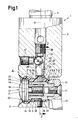
- a conventional boring tool 1 is shown in different sectional views.
- the boring tool 1 comprises a tool body 2 which can be clamped in a rotationally driven chuck of a machine tool by means of a shaft 3.
- a circular cylindrical bore 10 in the body 2 is lined in a manner known per se with a cast-in or pressed-in plastic sliding covering 4, which is firmly attached to the inner wall of the bore 10 via a groove 5 or the like.
- a tool slide 7 is slidably displaceable transversely to the axis of rotation 8 of the tool in the circular cylindrical bore 6 enclosed by the plastic sliding coating 4.
- the carriage 7 has one Bore 9, into which a screw 11 can be screwed.
- the screw 11 is used to fasten a tool carrier 12 to the slide 7.
- a conventional cutting tool in the form of a cutting plate 13 or the like is in turn fastened to the tool carrier 12.
- the turning radius of the tool 13 can be adjusted by correspondingly displacing the tool carriage 7 transversely to the axis of rotation 8.
- a bushing 15 e.g. by gluing, firmly inserted.
- the bushing 15 has a very fine internal thread, for example 0.25 mm pitch per revolution.
- the bore 10 is expanded accordingly.
- the plastic sliding covering 4 extends into this extension and partially envelops the head 18, a shoulder 30 being formed on the flat back 20 of the head 18, which runs perpendicular to the shaft 16 and against which the back 20 bears.
- An axial fixation or axial bearing of the micrometer screw 17 takes place according to the invention in such a way that a circumferential annular groove 21 is formed on the head 18 of the micrometer screw 17, in which a complementary annular bead 22 protruding from the plastic sliding lining 4 inwards engages.
- a plurality of axially adjacent grooves and beads can also be provided.
- the bead 22 is formed in a simple manner in that the micrometer screw 17 and the slide 7 are fixed in the bore 3 of the tool body 2 and then the plastic sliding coating 4 is poured in or pressed in.
- the sliding lining 4 fills all cavities available to it and in particular also penetrates into the annular groove 21, which results in the desired positive locking and the axial fixation of the micrometer screw 17 by itself.
- the head 18 of the micrometer screw 17 and the carriage 7 is coated in a known manner with a release agent, for example a silicone oil, before filling the plastic sliding coating, so that the coating only adheres to the body 2 of the tool, the head 18 of the micrometer screw but and the carriage 7 remain movable in the covering.
- a release agent for example a silicone oil
- a two-component synthetic resin compound based on epoxy resin that is customary for this purpose has become the plastic sliding covering with suitable fillers proved to be useful. Apparently, such masses can be loaded not only radially but also axially to a considerable extent without losing their dimensional stability.
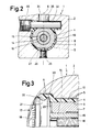
- the cross-sectional shapes of the annular groove 21 and the annular bead 22 are designed in the form of a segment of a circle, the segment preferably being somewhat smaller than a semicircle, cf. 3.
- the forces introduced radially from the annular groove 21 into the annular bead 22 can propagate to the opposite surface of the tool body 2, with which the sliding coating is attached. The forces then find their abutment on this surface.
- the stroke of the tool slide 7 is limited by a screw 25 which engages with an extension 26 in an axially extending groove 27 on the outer circumference of the slide 7.
- the tool slide 7 has on its upper side in FIGS. 1 and 2 a flat flattening 31, against which a bolt 32 arranged transversely to the sliding axis of the slide 7 rests with a flat 33.
- This bolt 32 serves to prevent rotation for the carriage 7 in the bore 6 and is secured by a screw 40 in the tool body 2 (FIG. 2).
- the plastic sliding covering 4 which forms the sliding bearing for the tool slide 7 with its inner wall, envelops not only this slide but also the bolt 32, the covering 4 being recessed in the area of the flattened area 33.
- a bolt 35 is slidably mounted in an axial bore 34 of the tool body 2 and engages with its one end face on the bolt 32.
- the opposite end surface 37 of the bolt 35 is formed obliquely.
- a ball 38 bears against it, which is prevented from moving axially toward the shaft 3 by a bolt 39 screwed into the body 2.
- the ball 38 By rotating a further screw bolt 41 in the tool body 2, the ball 38 can be displaced on the inclined surface 37, so that the bolt 35 is pressed onto the bolt 32.
- the bolt 32 is in turn pressed against the carriage 7 and prevents it from shifting and rotating in the bore 6 of the sliding lining 4.
- the screw bolt 41 and thus the described anti-rotation device is released, so that the carriage 7 is freely displaceable in the bore 6.
- the bolt 35 has a recess 42.
- a part 43 of the material forming the plastic sliding covering 4 has also penetrated into this recess when it is poured in.
- This part 43 of the sliding lining 4 in cooperation with the recess 42, fixes the bolt 35 in position and prevents it from rotating, so that the inclined surface 37 cannot change its position relative to the ball 38.
- the one-piece cast in the tool body 2 plastic slide lining 4 mediates a total of three functions in the embodiment described here: it forms the slide guide for the tool slide 7, it serves in the area of the annular groove 21 as an axial bearing for the micrometer screw 17 and he further mediates a position fixation of the bolt 35, which in turn is the actuator for the rotation lock formed by the bolt 32.
- the plastic sliding lining 4 naturally also forms a radial bearing for this head.
- the axial bearing (groove 21 / bead 22) formed here which is formed by the plastic sliding covering 4, does not necessarily have to be connected to an axial sliding bearing (for the slide 7).
- the example of the head 18 of the micrometer screw 17 clearly shows how both radial and axial support takes place on a simple rotary bearing.
- the plastic sliding coating 4 is firmly connected (via the corrugation 5) to the tool body 2, while the rotating component (head 18 of the micrometer screw 17) rotates relatively in the stationary sliding coating 4.
- the plastic sliding coating is firmly connected to the rotatable component and in turn rotates in the bearing bore (bore 10).
- the annular groove 21 must be formed on the bearing bore and the plastic sliding coating firmly attached to the rotating component must extend into this groove in the form of a radially outwardly projecting annular bead.
Landscapes
- Engineering & Computer Science (AREA)
- General Engineering & Computer Science (AREA)
- Mechanical Engineering (AREA)
- Sliding-Contact Bearings (AREA)
- Cutting Tools, Boring Holders, And Turrets (AREA)
- Machine Tool Units (AREA)
Abstract
Description
- Die Erfindung betrifft eine Drehlagerung mit einer Lagerbohrung, einem in dieser Bohrung drehbaren Bauteil und einem zwischen Bohrung und Bauteil eingegossenen Kunststoff-Gleitbelag.
- Bei bekannten Drehlagerungen dieser Art, wie sie beispielsweise an Maschinenteilen und Werkzeugen eingesetzt werden, dient der Kunststoff-Gleitbelag ausschließlich der (radialen) Lagerung eines rotierenden Bauteils in dessen Lagerbohrung.
- Um das rotierende Bauteil auch axial in der Lagerbohrung zu fixieren, ist es erforderlich, besondere Vorkehrungen zu treffen uns insbesondere axial aneinanderliegende Flächen am Bauteil und an der Bohrung vorzusehen, welche die gewünschte axiale Abstützung vermitteln. Bekannt ist in diesem Zusammenhang beispielsweise ein einschnappbarer Sicherungsring (Seeger-Ring). Die bisherigen Axialsicherungen drehender Bauteile sind in der Herstellung aufwendig und ermangeln zudem häufig der gewünschten Präzision.
- Es ist Aufgabe der Erfindung, eine gattungsgemäße Drehlagerung so weiterzubilden, daß das drehbare Bauteil in seiner Lagerbohrung ohne großen Fertigungsaufwand, jedoch äußerst genau auch eine axiale Abstützung findet.
- Die Aufgabe wird erfindungsgemäß dadurch gelöst, daß das drehbare Bauteil wenigstens eine Ringnut aufweist, in die zur Ausbildung eines Axiallagers der Kunststoff-Gleitbelag formschlüssig eingreift.
- Die nachstehende Beschreibung bevorzugter Ausführungsbeispiele der Erfindung dient im Zusammenhang mit beiliegender Zeichnung der weiteren Erläuterung. Es zeigen:
- Fig. 1 eine Axialschnittansicht eines Ausdrehwerkzeuges mit axial abgestützter Mikrometerschraube;
- Fig 2 eine Teilschnittansicht entlang der Linie 2-2 in Fig. 2 und
- Fig. 3 eine Einzeldarstellung im Bereich A der Fig. 1.
- Auf der Zeichnung ist ein übliches Ausdrehwerkzeug 1 in verschiedenen Schnittansichten dargestellt. Das Ausdrehwerkzeug 1 umfaßt einen Werkzeugkörper 2, der mittels eines Schaftes 3 in ein drehend angetriebenes Futter einer Werkeugmaschine eingespannt werden kann. Eine kreiszylindrische Bohrung 10 im Körper 2 ist in an sich bekannter Weise mit einem eingegossenen oder eingepreßten Kunststoff-Gleitbelag 4 ausgekleidet, der über eine Riefung 5 od. dgl. fest mit der Innenwand der Bohrung 10 verhaftet ist. In der vom Kunststoff-Gleitbelag 4 umschlossenen, ebenfalls kreiszylindrischen Bohrung 6 ist ein Werkzeugschlitten 7 quer zur Drehachse 8 des Werkzeuges gleitverschieblich. Der Schlitten 7 weist eine Bohrung 9 auf, in welche eine Schraube 11 eindrehbar ist. Die Schraube 11 dient der Befestigung eines Werkzeugträgers 12 am Schlitten 7. Am Werkzeugträger 12 ist seinerseits ein übliches Schneidwerkzeug in Gestalt einer Schneidplatte 13 od. dgl. befestigt. Durch entsprechendes Verschieben des Werkzeugschlittens 7 quer zur Drehachse 8 kann der Ausddrehradius des Werkzeuges 13 eingestellt werden.
- In eine weitere, zur Bohrung 9 koaxiale Bohrung 14 des Werkzeugschlittens 7 ist eine Buchse 15, z.B. durch Einklebung, fest eingesetzt. Die Buchse 15 weist ein sehr feines Innengewinde, von beispielsweise 0,25 mm Steigung pro Umlauf auf. Mit dem Innengewinde der Buchse 15 steht das entsprechende Außengewinde am Schaft 16 einer Mikrometerschraube 17 in Eingriff, deren Kopf mit 18 bezeichnet ist. Wenn die Mikrometerschraube 17 gedreht und dabei axial fixiert wird, verschiebt sich der Schlitten 7 und damit das Werkzeug 13 quer zur Drehachse 8.
- Im Bereich des Kopfes 18 der Mikrometerschraube 17 ist die Bohrung 10 entsprechend erweitert. Der Kunststoff-Gleitbelag 4 erstreckt sich in diese Erweiterung hinein und umhüllt den Kopf 18 teilweise, wobei an der ebenen, senkrecht zum Schaft 16 verlaufenden Rückseite 20 des Kopfes 18 eine Schulter 30 gebildet ist, an der die Rückseite 20 anliegt.
- Eine axiale Fixierung oder Axiallagerung der Mikrometerschraube 17 erfolgt erfindungsgemäß in der Weise, daß am Kopf 18 der Mikrometerschraube 17 eine rings umlaufende Ringnut 21 ausgebildet ist, in welche ein komplementär ausgebildeter, vom Kunststoff-Gleitbelag 4 nach einwärts abstehender Ringwulst 22 eingreift. Anstelle einer einzigen Ringnut 21 und eines einzigen Ringwulstes 22 können auch mehrere, axial nebeneinanderliegende Nuten und Wulste vorgesehen werden.
- Der Wulst 22 wird in einfacher Weise dadurch gebildet, daß die Mikrometerschraube 17 und der Schlitten 7 in der Bohrung 3 des Werkzeugkörpers 2 fixiert werden und hierauf der Kunststoff-Gleitbelag 4 eingegossen oder eingepreßt wird. Der Gleitbelag 4 füllt dabei alle ihm zur Vergügung stehenden Hohlräume aus und dringt insbesondere auch in die Ringnut 21 ein, wodurch sich der erwünschte Formschluß und die axiale Fixierung der Mikrometerschraube 17 von alleine ergeben. Der Kopf 18 der Mikrometerschraube 17 und der Schlitten 7 wird vor dem Einfüllen des Kunststoff-Gleitbelages in bekannter Weise mit einem Trennmittel, beispielsweise ein Silikonöl, beschichtet, so daß sich der Belag nur mit dem Körper 2 des Werkzeuges verhaftet, der Kopf 18 der Mikrometerschraube aber und der Schlitten 7 im Belag beweglich bleiben.
- Es ist offensichtlich, daß diese Art einer Axiallagerung außerordentlich einfach herzustellen ist, weil sie sich automatisch bei dem ohnehin vorzunehmenden Einbringen des Kunststoff-Gleitbelages 4 ergibt. Die beschriebene Axiallagerung ist aber nicht nur in einfachster Weise herstellbar sondern auch überaus genau und widerstandsfähig. Es hat sich gezeigt, daß die erzielbare Genauigkeit im Mikrometer-Bereich, beispielsweise bei 1µm liegt, und der in die Ringnut 21 eingreifende Ringwulst 22 des Kunststoff-Gleitbelags 4 Kräften von mehreren hundert Kilogramm ohne weiteres widersteht.
- Als Kunststoff-Gleitbelag hat sich eine für diesen Zweck übliche Zweikomponenten-Kunstharzmasse auf Epoxidharzbasis mit geeigneten Füllstoffen als brauchbar erwiesen. Offenbar sind derartige Massen nicht nur radial sondern auch axial in erheblichem Maße belastbar, ohne an Formbeständigkeit einzubüßen.
- Von besonderem Vorteil ist es, wenn die Querschnittsformen von Ringnut 21 und Ringwulst 22 kreissegmentförmig ausgebildet werden, wobei das Segment vorzugsweise etwas kleiner als ein Halbkreis ist, vgl. Fig. 3. Bei dieser Querschnittsform können nämlich die radial von der Ringnut 21 in den Ringwulst 22 eingeleiteten Kräfte sich bis zur gegenüberliegenden Fläche des Werkzeugkörpers 2 fortpflanzen, mit welcher der Gleitbelag verhaftet ist. An dieser Fläche finden die Kräfte dann ihr Widerlager.
- Bei der dargestellten Ausführungsform eines Ausdrehwerkzeuges 1 ist der Hub des Werkzeugschlittens 7 durch eine Schraube 25 begrenzt, die mit einem Fortsatz 26 in eine axial verlaufende Nut 27 am Außenumfang des Schlittens 7 eingreift.
- Der Werkzeugschlitten 7 weist an seiner in Fig. 1 und 2 oben liegenden Seiten eine ebene Abflachung 31, an welcher ein quer zur Verschiebeachse des Schlittens 7 angeordneter Bolzen 32 mit einer Abflachung 33 anliegt. Dieser Bolzen 32 dient als Verdrehungssicherung für den Schlitten 7 in der Bohrung 6 und ist durch eine Schraube 40 im Werkzeugkörper 2 gesichert (Fig. 2). Wie dargestellt, umhüllt der Kunststoff-Gleitbelag 4, der mit seiner Innenwand das Gleitlager für den Werkzeugschlitten 7 bildet, nicht nur diesen Schlitten sondern auch den Bolzen 32, wobei der Belag 4 im Bereich der Abflachung 33 ausgespart ist.
- In einer axialen Bohrung 34 des Werkzeugkörpers 2 ist ein Bolzen 35 verschieblich gelagert, der mit seiner einen Stirnfläche am Bolzen 32 angreift. Die gegenüberliegende Endfläche 37 des Bolzens 35 ist schräg ausgebildet. An ihr liegt eine Kugel 38 an, die durch einen in den Körper 2 eingeschraubten Bolzen 39 an einer axial zum Schaft 3 hin gerichteten Bewegung gehindert ist. Durch Verdrehen eines weiteren Schraubbolzens 41 im Werkzeugkörper 2 kann die Kugel 38 auf der Schrägfläche 37 verschoben werden, so daß der Bolzen 35 auf den Bolzen 32 gedrückt wird. Hierdurch wird der Bolzen 32 seinerseits gegen den Schlitten 7 gepreßt und hindert diesen an einer Verschiebung und Drehung in der Bohrung 6 des Gleitbelags 4. Vor einer Verstellung des Schlittens 7 mit Hilfe der Mikrometerschraube 17 wird der Schraubbolzen 41 und damit die beschriebene Verdrehungssicherung gelöst, so daß der Schlitten 7 in der Bohrung 6 frei verschieblich ist.
- Wie in Fig. 1 dargestellt, weist der Bolzen 35 eine Aussparung 42 auf. In diese Aussparung ist ein Teil 43 des den Kunststoff-Gleitbelag 4 bildenden Materials bei dessen Eingießen miteingedrungen. Dieser Teil 43 des Gleitbelages 4 bildet im Zusammenwirken mit der Aussparung 42 eine Lagefixierung des Bolzens 35 und hindert diesen an einer Verdrehung, so daß die Schrägfläche 37 ihre Lage relativ zur Kugel 38 nicht verändern kann. Der einstückig in den Werkzeugkörper 2 eingegegossene Kunststoff-Gleitbelag 4 vermittelt bei dem hier beschriebenen Ausführungsbeispiel somit insgesamt drei Funktionen: er bildet einmal die Gleitführung für den Werkzeugschlitten 7, er dient im Bereich der Ringnut 21 als Axiallager für die Mikrometerschraube 17 und er vermittelt weiterhin eine Lagefixierung des Bolzens 35, der seinerseits das Betätigungsglied für die vom Bolzen 32 gebildete Drehsicherung ist.
- Im Bereich des Kopfes 18 der Mikrometerschraube 7 bildet der Kunststoff-Gleitbelag 4 selbstverständlich gleichzeitig auch ein Radiallager für diesen Kopf.
- Es ist selbstverständlich, daß das hier beschriebene, vom Kunststoff-Gleitbelag 4 gebildete Axiallager (Nut 21/ Wulst 22) nicht unbedingt mit einem axialen Gleitlager (für den Schlitten 7) verbunden zu werden braucht. Am Beispiel des Kopfes 18 der Mikrometerschraube 17 ist deutlich ersichtlich, wie an einer einfachen Drehlagerung sowohl eine radiale als auch axiale Abstützung stattfindet.
- Bei dem dargestellten Ausführungsbeispiel ist der Kunststoff-Gleitbelag 4 (über die Riffelung 5) fest mit dem Werkzeugkörper 2 verbunden, während sich das drehende Bauteil (Kopf 18 der Mikrometerschraube 17) relativ im ortsfesten Gleitbelag 4 verdreht. Grundsätzlich wäre auch eine umgekehrte Ausbildung derart denkbar, daß der Kunstoff-Gleitbelag fest mit dem drehbaren Bauteil verbunden ist und sich seinerseits in der Lagerbohrung (Bohrung 10) dreht. In diesem Falle muß natürlich die Ringnut 21 an der Lagerbohrung ausgebildet sein und der fest mit dem drehenden Bauteil verhaftete Kunststoff-Gleitbelag muß sich in diese Nut in Form eines radial nach außen abstehenden Ringwulstes hinein erstrecken.
Claims (9)
dadurch gekennzeichnet,
daß das drehbare Bauteil (18) wenigstens eine Ringnut (21) aufweist, in die zur Ausbildung eines Axiallagers der Kunststoff-Gleitbelag (4) formschlüssig eingreift.
Applications Claiming Priority (2)
| Application Number | Priority Date | Filing Date | Title |
|---|---|---|---|
| DE3620696 | 1986-06-20 | ||
| DE3620696A DE3620696C2 (de) | 1986-06-20 | 1986-06-20 | Ausdrehwerkzeug |
Publications (3)
| Publication Number | Publication Date |
|---|---|
| EP0249892A2 true EP0249892A2 (de) | 1987-12-23 |
| EP0249892A3 EP0249892A3 (en) | 1988-02-17 |
| EP0249892B1 EP0249892B1 (de) | 1990-01-24 |
Family
ID=6303331
Family Applications (1)
| Application Number | Title | Priority Date | Filing Date |
|---|---|---|---|
| EP87108458A Expired - Lifetime EP0249892B1 (de) | 1986-06-20 | 1987-06-11 | Ausdrehwerkzeug |
Country Status (4)
| Country | Link |
|---|---|
| EP (1) | EP0249892B1 (de) |
| JP (1) | JPS63186027A (de) |
| DE (1) | DE3620696C2 (de) |
| ES (1) | ES2012785B3 (de) |
Cited By (3)
| Publication number | Priority date | Publication date | Assignee | Title |
|---|---|---|---|---|
| EP0791421A1 (de) * | 1996-02-22 | 1997-08-27 | Heinz Kaiser AG | Verbindung zwischen einem Schneidenhalter und einem Werkzeugträger eines Ausdrehkopfes |
| US8322952B2 (en) * | 2004-08-31 | 2012-12-04 | E.B.P | Bore head |
| EP4019174A1 (de) * | 2020-12-23 | 2022-06-29 | Seco Tools Tooling Systems | Bohrkopf und bohrwerkzeuganordnung |
Families Citing this family (2)
| Publication number | Priority date | Publication date | Assignee | Title |
|---|---|---|---|---|
| DE4242063C2 (de) * | 1992-12-14 | 1995-02-23 | Wohlhaupter Gmbh | Ausdrehwerkzeug |
| JP5092506B2 (ja) * | 2007-04-06 | 2012-12-05 | 株式会社タンガロイ | 微調整機構およびこれを備えたスローアウェイ式切削工具 |
Family Cites Families (8)
| Publication number | Priority date | Publication date | Assignee | Title |
|---|---|---|---|---|
| FR1266970A (fr) * | 1960-09-08 | 1961-07-17 | Unité d'usinage | |
| GB1187956A (en) * | 1966-12-01 | 1970-04-15 | Ultra Electronics Ltd | Shaft Bearing. |
| DE1988009U (de) * | 1967-08-04 | 1968-06-20 | Bosch Gmbh Robert | Gelenk fuer antriebsgestaenge, insbesondere von fahrzeugscheibenwischern. |
| DE2264912A1 (de) * | 1972-12-08 | 1975-05-28 | Acousa Saxon Sa | Kombiniertes axial-radial-lager |
| DE2354158A1 (de) * | 1973-10-29 | 1975-05-07 | Geb Oehrig Edith Boening | Gleitlager ohne schmierstoffe mit axialsicherung und nichtmetallischen fuellstoffen in kompaktbauweise |
| JPS51158948U (de) * | 1975-06-12 | 1976-12-17 | ||
| US4033020A (en) * | 1975-08-04 | 1977-07-05 | Trw Inc. | Method of making a slip joint |
| DE7837851U1 (de) * | 1978-12-21 | 1979-03-22 | Skf Kugellagerfabriken Gmbh, 8720 Schweinfurt | Einbaufertiges Gleitlager |
-
1986
- 1986-06-20 DE DE3620696A patent/DE3620696C2/de not_active Expired - Fee Related
-
1987
- 1987-06-11 ES ES87108458T patent/ES2012785B3/es not_active Expired - Lifetime
- 1987-06-11 EP EP87108458A patent/EP0249892B1/de not_active Expired - Lifetime
- 1987-06-19 JP JP62151531A patent/JPS63186027A/ja active Granted
Cited By (6)
| Publication number | Priority date | Publication date | Assignee | Title |
|---|---|---|---|---|
| EP0791421A1 (de) * | 1996-02-22 | 1997-08-27 | Heinz Kaiser AG | Verbindung zwischen einem Schneidenhalter und einem Werkzeugträger eines Ausdrehkopfes |
| US5857811A (en) * | 1996-02-22 | 1999-01-12 | Heinz Kaiser Ag | Connection between a cutter holder and a tool carrier of an internal-turning head |
| US8322952B2 (en) * | 2004-08-31 | 2012-12-04 | E.B.P | Bore head |
| EP4019174A1 (de) * | 2020-12-23 | 2022-06-29 | Seco Tools Tooling Systems | Bohrkopf und bohrwerkzeuganordnung |
| WO2022135793A1 (en) * | 2020-12-23 | 2022-06-30 | Seco Tools Tooling Systems | A boring head and a boring tool assembly |
| CN116323054A (zh) * | 2020-12-23 | 2023-06-23 | 山高刀具系统公司 | 镗孔刀头和镗孔刀具组件 |
Also Published As
| Publication number | Publication date |
|---|---|
| EP0249892A3 (en) | 1988-02-17 |
| DE3620696C2 (de) | 1996-10-02 |
| ES2012785B3 (es) | 1990-04-16 |
| JPS63186027A (ja) | 1988-08-01 |
| EP0249892B1 (de) | 1990-01-24 |
| DE3620696A1 (de) | 1987-12-23 |
| JPH0455802B2 (de) | 1992-09-04 |
Similar Documents
| Publication | Publication Date | Title |
|---|---|---|
| EP1827761B1 (de) | Spannvorrichtung mit zentriervorrichtung an einem schleifspindelrotor und rotationsteil mit einer derartigen zentriervorrichtung | |
| DE2114802B2 (de) | Kardanbiegegelenk | |
| DE3642230C2 (de) | Inkrementaler oder absoluter Drehgeber mit einer Klemmvorrichtung | |
| DE10358897A1 (de) | Verstellbarer Winkelhaken mit Schnappverschluss bei bestimmten Drehungswinkel | |
| DE2137698B2 (de) | Lösbare Drehwinkelfeststelleinrichtung an Werkzeugmaschinen in An wendung auf einen Rundschalttisch | |
| EP2300184A1 (de) | Werkzeug mit befestigungseinrichtung | |
| EP0164582B1 (de) | Spannelement zum zentrischen Spannen rotierender Teile | |
| EP0249892B1 (de) | Ausdrehwerkzeug | |
| DE3706123C2 (de) | ||
| DE2241608B2 (de) | In eine Arbeitsspindel einsetzbares Werkzeugfutter | |
| DE69215905T2 (de) | Spannvorrichtung für fräser oder ähnliche, anpassbar für verschiedene haltergrössen | |
| EP0087623A1 (de) | Verfahren zur Herstellung einer auf einer Gewindespindel laufenden Doppelmutter | |
| EP1782918B1 (de) | Aufnahme für ein Schleifwerkzeug, Schleifwerkzeug und Tragkörper für ein Schleifwerkzeug | |
| DE3433492C2 (de) | ||
| DE2653629C2 (de) | Verfahren zur Herstellung eines Wellenlagers | |
| DE102017213063A1 (de) | Zerspanungswerkzeug mit einer stelleinrichtung | |
| DE4020354C2 (de) | ||
| DE2150604C3 (de) | Dynamisch abstimmbares umlaufendes Federkardangelenk | |
| DE3150030C1 (de) | Riemenscheibe | |
| EP0523541B1 (de) | Manuell betriebener Rundschalttisch | |
| DE3930573A1 (de) | Drehanoden-roentgenroehre | |
| EP3246118B1 (de) | Werkzeugträger | |
| EP1528210A2 (de) | Vorrichtung zum Justieren eines Baukörpers | |
| EP3233375A1 (de) | Aufnahme für einen kolben eines verbrennungsmotors zur bearbeitung des kolbens sowie verwendung der aufnahme | |
| EP0282936A2 (de) | Lagervorrichtung |
Legal Events
| Date | Code | Title | Description |
|---|---|---|---|
| PUAI | Public reference made under article 153(3) epc to a published international application that has entered the european phase |
Free format text: ORIGINAL CODE: 0009012 |
|
| AK | Designated contracting states |
Kind code of ref document: A2 Designated state(s): CH ES FR GB IT LI |
|
| PUAL | Search report despatched |
Free format text: ORIGINAL CODE: 0009013 |
|
| AK | Designated contracting states |
Kind code of ref document: A3 Designated state(s): CH ES FR GB IT LI |
|
| 17P | Request for examination filed |
Effective date: 19880701 |
|
| 17Q | First examination report despatched |
Effective date: 19880915 |
|
| GRAA | (expected) grant |
Free format text: ORIGINAL CODE: 0009210 |
|
| AK | Designated contracting states |
Kind code of ref document: B1 Designated state(s): CH ES FR GB IT LI |
|
| ITF | It: translation for a ep patent filed | ||
| GBT | Gb: translation of ep patent filed (gb section 77(6)(a)/1977) | ||
| ET | Fr: translation filed | ||
| PLBE | No opposition filed within time limit |
Free format text: ORIGINAL CODE: 0009261 |
|
| STAA | Information on the status of an ep patent application or granted ep patent |
Free format text: STATUS: NO OPPOSITION FILED WITHIN TIME LIMIT |
|
| 26N | No opposition filed | ||
| ITTA | It: last paid annual fee | ||
| PGFP | Annual fee paid to national office [announced via postgrant information from national office to epo] |
Ref country code: CH Payment date: 19960517 Year of fee payment: 10 |
|
| PGFP | Annual fee paid to national office [announced via postgrant information from national office to epo] |
Ref country code: GB Payment date: 19960531 Year of fee payment: 10 |
|
| PGFP | Annual fee paid to national office [announced via postgrant information from national office to epo] |
Ref country code: FR Payment date: 19960607 Year of fee payment: 10 Ref country code: ES Payment date: 19960607 Year of fee payment: 10 |
|
| PG25 | Lapsed in a contracting state [announced via postgrant information from national office to epo] |
Ref country code: GB Free format text: LAPSE BECAUSE OF NON-PAYMENT OF DUE FEES Effective date: 19970611 |
|
| PG25 | Lapsed in a contracting state [announced via postgrant information from national office to epo] |
Ref country code: ES Free format text: LAPSE BECAUSE OF EXPIRATION OF PROTECTION Effective date: 19970612 |
|
| PG25 | Lapsed in a contracting state [announced via postgrant information from national office to epo] |
Ref country code: LI Free format text: LAPSE BECAUSE OF NON-PAYMENT OF DUE FEES Effective date: 19970630 Ref country code: CH Free format text: LAPSE BECAUSE OF NON-PAYMENT OF DUE FEES Effective date: 19970630 |
|
| GBPC | Gb: european patent ceased through non-payment of renewal fee |
Effective date: 19970611 |
|
| REG | Reference to a national code |
Ref country code: CH Ref legal event code: PL |
|
| PG25 | Lapsed in a contracting state [announced via postgrant information from national office to epo] |
Ref country code: FR Free format text: LAPSE BECAUSE OF NON-PAYMENT OF DUE FEES Effective date: 19980227 |
|
| REG | Reference to a national code |
Ref country code: FR Ref legal event code: ST |
|
| REG | Reference to a national code |
Ref country code: FR Ref legal event code: ST |
|
| REG | Reference to a national code |
Ref country code: ES Ref legal event code: FD2A Effective date: 20000201 |
|
| PG25 | Lapsed in a contracting state [announced via postgrant information from national office to epo] |
Ref country code: IT Free format text: LAPSE BECAUSE OF NON-PAYMENT OF DUE FEES;WARNING: LAPSES OF ITALIAN PATENTS WITH EFFECTIVE DATE BEFORE 2007 MAY HAVE OCCURRED AT ANY TIME BEFORE 2007. THE CORRECT EFFECTIVE DATE MAY BE DIFFERENT FROM THE ONE RECORDED. Effective date: 20050611 |