EP0249686A2 - Luftgekühlte Mehrzylinder-Brennkraftmaschine - Google Patents
Luftgekühlte Mehrzylinder-Brennkraftmaschine Download PDFInfo
- Publication number
- EP0249686A2 EP0249686A2 EP87103878A EP87103878A EP0249686A2 EP 0249686 A2 EP0249686 A2 EP 0249686A2 EP 87103878 A EP87103878 A EP 87103878A EP 87103878 A EP87103878 A EP 87103878A EP 0249686 A2 EP0249686 A2 EP 0249686A2
- Authority
- EP
- European Patent Office
- Prior art keywords
- cylinders
- combustion engine
- internal combustion
- engine according
- deflecting part
- Prior art date
- Legal status (The legal status is an assumption and is not a legal conclusion. Google has not performed a legal analysis and makes no representation as to the accuracy of the status listed.)
- Granted
Links
Images


Classifications
-
- F—MECHANICAL ENGINEERING; LIGHTING; HEATING; WEAPONS; BLASTING
- F01—MACHINES OR ENGINES IN GENERAL; ENGINE PLANTS IN GENERAL; STEAM ENGINES
- F01P—COOLING OF MACHINES OR ENGINES IN GENERAL; COOLING OF INTERNAL-COMBUSTION ENGINES
- F01P1/00—Air cooling
- F01P1/02—Arrangements for cooling cylinders or cylinder heads, e.g. ducting cooling-air from its pressure source to cylinders or along cylinders
-
- F—MECHANICAL ENGINEERING; LIGHTING; HEATING; WEAPONS; BLASTING
- F02—COMBUSTION ENGINES; HOT-GAS OR COMBUSTION-PRODUCT ENGINE PLANTS
- F02F—CYLINDERS, PISTONS OR CASINGS, FOR COMBUSTION ENGINES; ARRANGEMENTS OF SEALINGS IN COMBUSTION ENGINES
- F02F1/00—Cylinders; Cylinder heads
- F02F1/24—Cylinder heads
- F02F1/26—Cylinder heads having cooling means
- F02F1/28—Cylinder heads having cooling means for air cooling
- F02F1/30—Finned cylinder heads
- F02F1/34—Finned cylinder heads with means for directing or distributing cooling medium
Definitions
- the invention relates to an air-cooled multi-cylinder internal combustion engine according to the preamble of claim 1.
- Such an internal combustion engine is known from DE-AS 1 205 772.
- the cooling air flowing in transverse to the cylinders flows along the broad side of the transverse ribs and is deflected on the rear cooling air outflow side of the cylinders by columns which are designed to be streamlined.
- baffles are attached to the pillars, the type of fastening of which is not specified. Such baffles are usually screwed on and cause undesirable noise emissions.
- the object of the invention is to provide an air guiding device which can be produced and assembled at low cost and does not constitute an additional source of noise.
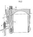
- FIGS. 1 and 2 three individually cast cylinders 2, 3, 4 are arranged in a row next to one another in a crankcase 1 of an internal combustion engine and together with the cylinder heads 6 with the crankcase 1 placed on the cylinders 2, 3, 4 by means of expansion screws 5 screwed.
- the cylinders 2, 3, 4 are provided all around with ribs 7 extending transversely to their longitudinal axis, between which cooling air is blown through.
- a deflecting part 8 covering all cylinders, which is cast in one piece from light metal and is attached to the crankcase at its three fastening eyes 9 located centrally to the cylinders 2, 3, 4 and screwed to it.
- the deflection part 8 is double-walled.
- the fastening eyes 9 are located in the center of the air outlet openings 10, which are arranged in the area of the center planes 2 ', 3', 4 'of the cylinders, run radially to the cylinders and extend over their entire height.
- the deflecting part In the area between the cylinders 2, 3 and 3, 4, the deflecting part has V-shaped bends 11 pointing towards the cylinders 2, 3, 4, at which the cooling air flowing between the cylinders is deflected by 90 ° and led to the air outlet openings 10 becomes.
- This deflecting part 12 also serves as a knocking bridge in addition to the air guidance, in that it forwards the noise coming from the cylinders caused by knocking combustion to a knocking sensor 15 which is screwed onto the deflecting part 12 approximately in the middle of its longitudinal extent.
Landscapes
- Engineering & Computer Science (AREA)
- Chemical & Material Sciences (AREA)
- Combustion & Propulsion (AREA)
- Mechanical Engineering (AREA)
- General Engineering & Computer Science (AREA)
- Cylinder Crankcases Of Internal Combustion Engines (AREA)
Abstract
Description
- Die Erfindung betrifft eine luftgekühlte Mehrzylinder-Brennkraftmaschine nach dem Oberbegriff des Anspruchs 1.
- Eine derartige Brennkraftmaschine ist aus DE-AS 1 205 772 bekannt. Die quer zu den Zylindern zuströmende Kühlluft strömt entlang der Breitseite der Querrippen und wird an der rückwärtigen Kühlluftabströmseite der Zylinder durch strömungsgünstig gestaltete Säulen umgelenkt. Zusätzlich sind an den Säulen Leitbleche angebracht, über deren Befestigungsart keine Angaben gemacht sind. Üblicherweise werden solche Leitbleche angeschraubt und verursachen eine unerwünschte Geräuschemission.
- Die Aufgabe der Erfindung besteht darin, eine Luftleitvorrichtung zu schaffen, die mit geringen Kosten herstellbar und montierbar ist und keine zusätzliche Geräuschquelle darstellt.
- Zur Lösung dieser Aufgabe dient als Luftleitvorrichtung ein einstückiges, alle Zylinder an ihrer Kühlluftabströmseite abdeckendes Umlenkteil, das aus Leichtmetall gegossen oder aus Kunststoff gespritzt sein kann. Zur Erhöhung der Formsteifigkeit ist es doppelwandig gestaltet. Dieses Umlenkteil ist entweder mit dem Kurbelgehäuse oder den Zylindern verschraubt. Es kann im letzteren Falle zugleich als Klopfbrücke verwendet werden, indem es die Klopfgeräusche aller mit ihm verbundenen Zylinder an einen mittig an ihm angeschraubten Klopfsensor weiterleitet. Wenn das Umlenkteil aus einem Werkstoff gefertigt ist, der den gleichen Wärmeausdehnungskoeffizienten hat wie das Kurbelgehäuse, folgt es bei Temperaturänderungen dessen Längendehnung, so daß das Umlenkteil starr an die im Kurbelgehäuse befestigten Zylinder angeschraubt sein kann. Ansonsten kann auch eine ausgleichende Schraubenverbindung gewählt werden, die eine unterschiedliche Längenausdehnung von Umlenkteil und Kurbelgehäuse ermöglicht.
- Zwei Ausführungsformen der Erfindung sind in der Zeichnung dargestellt und werden nachstehend erläutert.
- Es zeigt
- Fig. 1 Querschnitt durch eine Zylinderreihe einer luftgekühlten Sechszylinder-Brennkraftmaschine,
- Fig. 2 Längsschnitt durch einen Zylinder mit Umlenkteil nach der Linie II-II der Fig. 1,
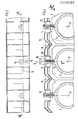
- Fig. 3 Seitenansicht eines Umlenkteils mit Klopfsensor,
- Fig. 4 Querschnitt durch eine Zylinderreihe nach Linie IV-IV der Fig. 3,
- Fig. 5 Schnitt durch eine Linie V-V der Fig. 2 mit Längsschnitt durch einen Zylinder.
- Nach Fig. 1 und Fig. 2 sind in einem Kurbelgehäuse 1 einer Brennkraftmaschine drei einzeln gegossene Zylinder 2, 3, 4 in Reihe nebeneinander angeordnet und durch Dehnschrauben 5 gemeinsam mit den auf die Zylinder 2, 3, 4 aufgesetzten Zylinderköpfen 6 mit dem Kurbelgehäuse 1 verschraubt. Die Zylinder 2, 3, 4 sind außen ringsum mit quer zu ihrer Längsachse verlaufenden Rippen 7 versehen, zwischen denen Kühlluft hindurchgeblasen wird. An der Kühlluftabströmseite der Zylinder ist ein alle Zylinder abdeckendes Umlenkteil 8 angeordnet, das einstückig aus Leichtmetall gegossen und an seinen drei mittig zu den Zylindern 2, 3, 4 liegenden Befestigungsaugen 9 auf das Kurbelgehäuse aufgesetzt und mit ihm verschraubt ist. Zur Erhöhung der Formsteifigkeit ist das Umlenkteil 8 doppelwandig ausgeführt. Die Befestigungsaugen 9 liegen mittig zu den Luftaustrittsöffnungen 10, die im Bereich der Mittenebenen 2', 3', 4' der Zylinder angeordnet sind, radial zu den Zylindern verlaufen und sich über deren ganze Höhe erstrecken. Im Bereich zwischen den Zylindern 2, 3 und 3, 4 weist das Umlenkteil V-förmige, zu den Zylindern 2, 3, 4 hinweisende Einknickungen 11 auf, an denen die zwischen den Zylindern durchströmende Kühlluft um 90 ° umgelenkt und zu den Luftaustrittsöffnungen 10 hingeführt wird.
- Bei einer Ausführungsform der Erfindung gemäß Fig. 3, 4 und 5 unterscheidet sich das Umlenkteil 12 dadurch vom Umlenkteil 9, daß es radial zu den Zylindern verlaufende Augen 13 aufweist, mit denen es auf entsprechende Augen 14 der Zylinder 2, 3, 4 aufgesetzt und mit ihnen verschraubt ist.
- Dieses Umlenkteil 12 dient neben der Luftführung zugleich als Klopfbrücke, indem es die aus den Zylindern kommenden, durch klopfende Verbrennung verursachten Geräusche zu einem Klopfsensor 15 weiterleitet, der am Umlenkteil 12 etwa mittig seiner Längserstreckung angeschraubt ist.
Claims (9)
Applications Claiming Priority (2)
| Application Number | Priority Date | Filing Date | Title |
|---|---|---|---|
| DE19863616636 DE3616636A1 (de) | 1986-05-16 | 1986-05-16 | Luftgekuehlte mehrzylinder-brennkraftmaschine |
| DE3616636 | 1986-05-16 |
Publications (3)
| Publication Number | Publication Date |
|---|---|
| EP0249686A2 true EP0249686A2 (de) | 1987-12-23 |
| EP0249686A3 EP0249686A3 (en) | 1988-11-30 |
| EP0249686B1 EP0249686B1 (de) | 1991-07-17 |
Family
ID=6301029
Family Applications (1)
| Application Number | Title | Priority Date | Filing Date |
|---|---|---|---|
| EP87103878A Expired - Lifetime EP0249686B1 (de) | 1986-05-16 | 1987-03-17 | Luftgekühlte Mehrzylinder-Brennkraftmaschine |
Country Status (5)
| Country | Link |
|---|---|
| US (1) | US4779588A (de) |
| EP (1) | EP0249686B1 (de) |
| JP (1) | JPS62271921A (de) |
| DE (2) | DE3616636A1 (de) |
| ES (1) | ES2025079B3 (de) |
Cited By (1)
| Publication number | Priority date | Publication date | Assignee | Title |
|---|---|---|---|---|
| AT501201B1 (de) * | 2005-01-13 | 2006-11-15 | Avl List Gmbh | Luftgekühlte brennkraftmaschine |
Families Citing this family (8)
| Publication number | Priority date | Publication date | Assignee | Title |
|---|---|---|---|---|
| JPH088282Y2 (ja) * | 1988-04-06 | 1996-03-06 | 日産自動車株式会社 | 内燃機関のv型シリンダブロック |
| US5967326A (en) * | 1998-07-22 | 1999-10-19 | Tessler & Weiss/Premesco, Inc. | Tray for displaying a plurality of jewelry items and information relating to the jewelry items |
| US7918195B2 (en) * | 2007-02-09 | 2011-04-05 | George McCall, III | Air-cooled engine heat extractor |
| JP2013024099A (ja) | 2011-07-20 | 2013-02-04 | Yamaha Motor Co Ltd | 内燃機関およびそれを備えた鞍乗型車両 |
| JP2013024101A (ja) * | 2011-07-20 | 2013-02-04 | Yamaha Motor Co Ltd | 内燃機関およびそれを備えた鞍乗型車両 |
| JP2013024100A (ja) | 2011-07-20 | 2013-02-04 | Yamaha Motor Co Ltd | 内燃機関およびそれを備えた鞍乗型車両 |
| JP2016011587A (ja) * | 2014-06-27 | 2016-01-21 | 本田技研工業株式会社 | ユニットスイングエンジンにおけるノックセンサ取付け構造 |
| US11898485B2 (en) * | 2020-05-03 | 2024-02-13 | Amnon Yaacobi | Method and system for controlling the temperature of an engine |
Family Cites Families (13)
| Publication number | Priority date | Publication date | Assignee | Title |
|---|---|---|---|---|
| GB163140A (en) * | 1920-02-21 | 1921-05-19 | William Tranton Sidebottom | Improvements connected with air cooled cylinders of internal combustion engines |
| GB475887A (en) * | 1936-05-28 | 1937-11-29 | Arthur John Rowledge | Improvements in cooling means for air cooled cylinders of internal combustion engines |
| US2424416A (en) * | 1944-01-06 | 1947-07-22 | Fairchild Engine & Airplane | Engine cooling system |
| US2729201A (en) * | 1954-10-28 | 1956-01-03 | Avco Mfg Corp | Cylinder baffle for air-cooled engine |
| DE1205772B (de) * | 1960-03-10 | 1965-11-25 | Kloeckner Humboldt Deutz Ag | Luftgekuehlte Brennkraftmaschine |
| DE1232398B (de) * | 1961-06-09 | 1967-01-12 | Linde Ag | Luftgekuehlte Kolbenbrennkraftmaschine |
| FR1349691A (fr) * | 1963-02-28 | 1964-01-17 | Lindes Eismaschinen Ag | Moteur à combustion interne à refroidissement par air |
| US4047508A (en) * | 1975-12-08 | 1977-09-13 | Avco Corporation | Cooling air distribution system for reciprocating aircraft engines |
| GB2052388A (en) * | 1979-06-02 | 1981-01-28 | Nissan Motor | Noise reducing cover for an internal combustion engine |
| JPS5871136U (ja) * | 1981-11-05 | 1983-05-14 | 日産自動車株式会社 | 内燃機関のノツクセンサ取付構造 |
| US4452185A (en) * | 1983-02-09 | 1984-06-05 | The Toro Company | Engine housing |
| DE3408624A1 (de) * | 1984-03-09 | 1985-09-12 | KHD Canada Inc. Deutz R & D Division, Boucherville, Quebec | Luftgekuehlte hubkolbenbrennkraftmaschine |
| US4515111A (en) * | 1984-04-19 | 1985-05-07 | Khd Canada Inc. | Air-cooled, reciprocating piston, internal combustion engine with cylinder heads forming arcuate or S-shaped cooling ducts therebetween |
-
1986
- 1986-05-16 DE DE19863616636 patent/DE3616636A1/de not_active Withdrawn
-
1987
- 1987-03-17 DE DE8787103878T patent/DE3771396D1/de not_active Expired - Lifetime
- 1987-03-17 ES ES87103878T patent/ES2025079B3/es not_active Expired - Lifetime
- 1987-03-17 EP EP87103878A patent/EP0249686B1/de not_active Expired - Lifetime
- 1987-05-14 JP JP62116061A patent/JPS62271921A/ja active Pending
- 1987-05-15 US US07/049,827 patent/US4779588A/en not_active Expired - Fee Related
Cited By (1)
| Publication number | Priority date | Publication date | Assignee | Title |
|---|---|---|---|---|
| AT501201B1 (de) * | 2005-01-13 | 2006-11-15 | Avl List Gmbh | Luftgekühlte brennkraftmaschine |
Also Published As
| Publication number | Publication date |
|---|---|
| ES2025079B3 (es) | 1992-03-16 |
| JPS62271921A (ja) | 1987-11-26 |
| US4779588A (en) | 1988-10-25 |
| DE3616636A1 (de) | 1987-11-19 |
| EP0249686A3 (en) | 1988-11-30 |
| EP0249686B1 (de) | 1991-07-17 |
| DE3771396D1 (de) | 1991-08-22 |
Similar Documents
| Publication | Publication Date | Title |
|---|---|---|
| DE1914162A1 (de) | Luftgekuehlte Brennkraftmaschine | |
| EP0065064A2 (de) | Ansaugsystem mit Schwingrohren | |
| WO1994004803A1 (de) | Saugrohranlage für eine mehrzylinder-brennkraftmaschine | |
| DE4437714C2 (de) | Zylinderkopfabdeckung | |
| EP0270784B1 (de) | Ansauganlage für eine mehrzylindrige Brennkraftmaschine | |
| EP0249686B1 (de) | Luftgekühlte Mehrzylinder-Brennkraftmaschine | |
| DE3519205A1 (de) | Befestigung einer abdeckhaube an einem zylinderkopf | |
| DE102007023545A1 (de) | Abgasanlage | |
| DE19633419C1 (de) | Zylinderblock einer Brennkraftmaschine | |
| DE4401296C2 (de) | Vorrichtung zur Montage von Automotoren | |
| DE60117460T2 (de) | Selbsttragender Ansaugkrümmer | |
| DE69838352T2 (de) | Brennkraftmaschine mit Kraftstoffdirekteinspritzung und Funkenzündung | |
| WO2003100237A1 (de) | Zylinderkopf einer brennkraftmaschine | |
| DE2331755C3 (de) | Saugrohranordnung an Hubkolben-Brennkraftmaschinen | |
| EP1053901B1 (de) | Kühler für Brennkraftmaschinen | |
| DE19813745B4 (de) | Herstellungsverfahren für einen Zylinderkopf eines Verbrennungsmotors | |
| DE19509002C2 (de) | Thermostatanbaupositionsstruktur | |
| DE2507977C3 (de) | Ansaugkrümmer für Brennkraftmaschinen mit einer Verdampfungszone | |
| DE942953C (de) | Zylinderkopf fuer luftgekuehlte Brennkraftmaschinen | |
| EP0123101B1 (de) | Zylinderkopf für eine luftgekühlte Hubkolbenbrennkraftmaschine | |
| DE4018620C2 (de) | Aufgeladener Dieselmotor | |
| DE2616835C2 (de) | Ansaugleitungsystem für eine Mehrzylinder-Brennkraf tmaschine | |
| EP0379476A2 (de) | Ansaugsystem für Brennkraftmaschinen mit mehreren Zylindern | |
| DE19746948C2 (de) | Zylinderblockstruktur für einen Fahrzeug-Verbrennungsmotor des V-Typs | |
| DE19722948A1 (de) | Vorrichtung zum Anbau an einen Verbrennungsmotor |
Legal Events
| Date | Code | Title | Description |
|---|---|---|---|
| PUAI | Public reference made under article 153(3) epc to a published international application that has entered the european phase |
Free format text: ORIGINAL CODE: 0009012 |
|
| AK | Designated contracting states |
Kind code of ref document: A2 Designated state(s): DE ES FR GB IT |
|
| PUAL | Search report despatched |
Free format text: ORIGINAL CODE: 0009013 |
|
| AK | Designated contracting states |
Kind code of ref document: A3 Designated state(s): DE ES FR GB IT |
|
| 17P | Request for examination filed |
Effective date: 19890408 |
|
| 17Q | First examination report despatched |
Effective date: 19890713 |
|
| GRAA | (expected) grant |
Free format text: ORIGINAL CODE: 0009210 |
|
| AK | Designated contracting states |
Kind code of ref document: B1 Designated state(s): DE ES FR GB IT |
|
| ITF | It: translation for a ep patent filed | ||
| REF | Corresponds to: |
Ref document number: 3771396 Country of ref document: DE Date of ref document: 19910822 |
|
| GBT | Gb: translation of ep patent filed (gb section 77(6)(a)/1977) | ||
| ET | Fr: translation filed | ||
| REG | Reference to a national code |
Ref country code: ES Ref legal event code: FG2A Ref document number: 2025079 Country of ref document: ES Kind code of ref document: B3 |
|
| PLBI | Opposition filed |
Free format text: ORIGINAL CODE: 0009260 |
|
| 26 | Opposition filed |
Opponent name: MOTORENFABRIK HATZ GMBH & CO. KG Effective date: 19920421 |
|
| PGFP | Annual fee paid to national office [announced via postgrant information from national office to epo] |
Ref country code: GB Payment date: 19930308 Year of fee payment: 7 |
|
| PGFP | Annual fee paid to national office [announced via postgrant information from national office to epo] |
Ref country code: ES Payment date: 19930315 Year of fee payment: 7 |
|
| PGFP | Annual fee paid to national office [announced via postgrant information from national office to epo] |
Ref country code: FR Payment date: 19930331 Year of fee payment: 7 |
|
| PGFP | Annual fee paid to national office [announced via postgrant information from national office to epo] |
Ref country code: DE Payment date: 19930407 Year of fee payment: 7 |
|
| PLBM | Termination of opposition procedure: date of legal effect published |
Free format text: ORIGINAL CODE: 0009276 |
|
| STAA | Information on the status of an ep patent application or granted ep patent |
Free format text: STATUS: OPPOSITION PROCEDURE CLOSED |
|
| 27C | Opposition proceedings terminated |
Effective date: 19931029 |
|
| PG25 | Lapsed in a contracting state [announced via postgrant information from national office to epo] |
Ref country code: GB Effective date: 19940317 |
|
| PG25 | Lapsed in a contracting state [announced via postgrant information from national office to epo] |
Ref country code: ES Free format text: LAPSE BECAUSE OF NON-PAYMENT OF DUE FEES Effective date: 19940318 |
|
| GBPC | Gb: european patent ceased through non-payment of renewal fee |
Effective date: 19940317 |
|
| PG25 | Lapsed in a contracting state [announced via postgrant information from national office to epo] |
Ref country code: FR Effective date: 19941130 |
|
| PG25 | Lapsed in a contracting state [announced via postgrant information from national office to epo] |
Ref country code: DE Effective date: 19941201 |
|
| REG | Reference to a national code |
Ref country code: FR Ref legal event code: ST |
|
| REG | Reference to a national code |
Ref country code: ES Ref legal event code: FD2A Effective date: 19990201 |
|
| PG25 | Lapsed in a contracting state [announced via postgrant information from national office to epo] |
Ref country code: IT Free format text: LAPSE BECAUSE OF NON-PAYMENT OF DUE FEES;WARNING: LAPSES OF ITALIAN PATENTS WITH EFFECTIVE DATE BEFORE 2007 MAY HAVE OCCURRED AT ANY TIME BEFORE 2007. THE CORRECT EFFECTIVE DATE MAY BE DIFFERENT FROM THE ONE RECORDED. Effective date: 20050317 |