EP0249640B1 - Mehrkanalstereowiedergabeapparat - Google Patents
Mehrkanalstereowiedergabeapparat Download PDFInfo
- Publication number
- EP0249640B1 EP0249640B1 EP86906934A EP86906934A EP0249640B1 EP 0249640 B1 EP0249640 B1 EP 0249640B1 EP 86906934 A EP86906934 A EP 86906934A EP 86906934 A EP86906934 A EP 86906934A EP 0249640 B1 EP0249640 B1 EP 0249640B1
- Authority
- EP
- European Patent Office
- Prior art keywords
- signal
- reproducing
- circuit
- channel stereo
- signals
- Prior art date
- Legal status (The legal status is an assumption and is not a legal conclusion. Google has not performed a legal analysis and makes no representation as to the accuracy of the status listed.)
- Expired - Lifetime
Links
Images


Classifications
-
- H—ELECTRICITY
- H04—ELECTRIC COMMUNICATION TECHNIQUE
- H04S—STEREOPHONIC SYSTEMS
- H04S3/00—Systems employing more than two channels, e.g. quadraphonic
- H04S3/02—Systems employing more than two channels, e.g. quadraphonic of the matrix type, i.e. in which input signals are combined algebraically, e.g. after having been phase shifted with respect to each other
-
- H—ELECTRICITY
- H04—ELECTRIC COMMUNICATION TECHNIQUE
- H04S—STEREOPHONIC SYSTEMS
- H04S3/00—Systems employing more than two channels, e.g. quadraphonic
-
- H—ELECTRICITY
- H04—ELECTRIC COMMUNICATION TECHNIQUE
- H04R—LOUDSPEAKERS, MICROPHONES, GRAMOPHONE PICK-UPS OR LIKE ACOUSTIC ELECTROMECHANICAL TRANSDUCERS; ELECTRIC HEARING AIDS; PUBLIC ADDRESS SYSTEMS
- H04R3/00—Circuits for transducers
- H04R3/04—Circuits for transducers for correcting frequency response
Definitions
- This invention relates to multi-channel stereo reproducing apparatus.
- the audio signal is generally reproduced by means of a Dolby surround-phonic 4-channel stereo reproducing system, so as to produce realistic sound.
- a video signal is recorded, and at the same time left front sound, right front sound, centre front sound and rear sound are respectively recorded.
- a left front signal L F , a right front signal R F , a centre front signal F and a rear signal B are respectively encoded and recorded.
- S/N signal-to-noise
- Figure 3 shows a frequency vs. response characteristics where the recording level is at 0 dB, -10 dB, -20 dB and -30 dB in this modified B-type Dolby system.
- L T and R T are optically recorded, in the case of, for example, a 35mm film, at a sound track portion located at a predetermined position of the film, using a brightness change system which carries out the recording on the basis of change of light and shade.
- the signals L T and R T thus optically recorded are decoded so as to produce the left composite signal L T , the right composite signal R T , a sum signal L T +R T , and a difference signal L T -R T .
- These four signal are reproduced by a left front loudspeaker, a right front loudspeaker, a centre front loudspeaker and a rear loudspeaker.
- the high frequency component of the rear signal B has been pre-emphasized by the modified B-type Dolby system as described above, upon reproducing, the high frequency component of the difference signal L T -R T is attenuated (de-emphasized) so as to make the total frequency characteristic flat relative to the rear signal B.
- the audio signal is reproduced by such a 4-channel stereo reproducing system, the sound effect is enhanced and realistic.
- Magnetic tapes and video discs of the screen music or the motion picture itself are also available on the market.
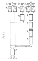
- the signals recorded on the magnetic tape and the video disc are the composite signals L T and R T as described above, there has been proposed a multi-channel stereo reproducing apparatus illustrated in Figure 1.
- the apparatus comprising left and right composite signal input terminals 1 and 2 to which the left and right composite signals L T and R T are supplied.
- the terminals 1 and 2 are connected to the input side of a balancing circuit 3 which produces left and right composite signals L T and R T which are so balanced as to localize an acoustic image normally.
- the outputs of the balancing circuit 3 are connected through amplifiers 4 and 5 to left and right front loudspeakers 6 and 7 which respectively reproduce the left and right composite signals L T and R T supplied to the terminals 1 and 2.
- the outputs of the balancing circuit 3 are connected to the input of a mixing circuit 8 which generates the sum signal L T +R T .
- the output of the mixing circuit 8 is connected through an amplifier 9 to a centre front loudspeaker 10 which reproduces the sum signal L T + R T developed at the output of the mixing circuit 8.
- the outputs of the balancing circuit 3 are connected to the input of a subtracting circuit 11 which generates the left and right composite signals L T and R T from which the monaural components are removed.
- the output of the subtracting circuit 11 is connected to the input of a delay circuit 12 which generates at its output side a delayed difference signal ⁇ t(L T -R T ), delayed by a predetermined time.
- the output of the delay circuit 12 is connected to the input of a low-pass filter 13 for passing therethrough a signal of a low frequency band, and the filter 13 generates at its output the delayed difference signal ⁇ t(L T -R T ) in which a clock pulse component resulting from passing the signal through the delay circuit 12 has been removed, and frequencies higher than a predetermined frequency are removed, so as to balance the low frequency component which is deficient in the difference signal L T -R T .
- the output of the low-pass filter 13 is connected to the input of a de-emphasis circuit 14 which attenuates the high frequency component of the delayed difference signal ⁇ t(L T -R T ) higher than 1 kHz, thus producing a delayed difference signal ⁇ t(L T -R T ) in which the total frequency characteristic of the rear signal B of which the high frequency component higher than 1 kHz has been emphasized is made flat.
- the output of the de-emphasis circuit 14 is connected through amplifiers 15 and 16 to left and right rear loudspeakers 17 and 18 by which the delayed difference signal ⁇ t(L T -R T ) in which the frequency characteristic of the rear signal B is made flat, is reproduced.
- the left and right composite signals L T and R T are reproduced from the left and right front loudspeakers 6 and 7, the sum signal L T +R T is reproduced from the centre front loudspeaker 10 and the delayed difference signal ⁇ t(L T -R T ) is reproduced from the left and right rear loudspeakers 17 and 18. Consequently, the sound effect is enhanced to produce good stereo presence.
- Japanese patent specification JP-A-54/62801 (GB-A-2 006 583)
- Japanese patent specification JP-A-49/120201 discloses a low-pass filter which can be selectively by-passed in a 2-channel or 4-channel stereo mode apparatus.
- the output of the low-pass filter 13 is connected to the input of the de-emphasis circuit 14 and to one fixed contact 19a of a change-over switch 19.
- the de-emphasis circuit 14 is modified to de-emphasize the high frequency component of the audio signal pre-emphasized by the modified B-type Dolby system, thereby to make the total frequency characteristic flat.
- the frequency characteristic of the de-emphasis circuit 14 may be such that when the signal level is about 30 dB, a signal level of a signal higher than about 4 kHz is emphasized by 5dB.
- the output of the de-emphasis circuit 14 is connected to the other fixed contact 19b of the switch 19, and a movable contact 19c thereof is connected through the amplifiers 15 and 16 to the left and right rear loudspeakers 17 and 18, whereby the de-emphasis circuit 14 can be by-passed, if necessary. Otherwise the arrangement is as shown in Figure 2.
- the left composite signal L T L F +F/2+B/2 is reproduced from the left front loudspeaker 6
- the delayed difference signal ⁇ t(L T -R T ) ⁇ t(L F -R F +B) is reproduced from the left and right rear loudspeakers 17 and 18.
- the movable contact 19c engages one fixed contact 19a to by-pass the de-emphasis circuit 14, thereby directly connecting the output of the low-pass filter 13 to the amplifiers 15 and 16, without attenuating the high frequency component of the delayed difference signal t(L F -R F ) obtained at the output of the low-pass filter 13, this delayed difference signal ⁇ t(L F -R F) can be reproduced.
- the delayed difference signal ⁇ t(L F -R F ) is reproduced together with the left front signal L F , the right front signal R F and the sum signal L F +R F , it is well known that stereo presence can be increased and hence the atmosphere of a concert hall or cinema can be obtained.
- the invention is applied to a multi-channel stereo reproducing apparatus for reproducing a recording medium on which a multi-channel stereo signal in which the rear signal B has been pre-emphasized by the modified B-type Dolby system is recorded
- the invention is not limited to this, but can be applied to a multi-channel stereo reproducing apparatus for reproducing a recording medium on which a signal pre-emphasized by another noise reduction system has been recorded, or an apparatus in which the above delay circuit is formed of a digital circuit comprising an A/D converter and a D/A converter.
Landscapes
- Physics & Mathematics (AREA)
- Engineering & Computer Science (AREA)
- Acoustics & Sound (AREA)
- Signal Processing (AREA)
- Algebra (AREA)
- General Physics & Mathematics (AREA)
- Mathematical Analysis (AREA)
- Mathematical Optimization (AREA)
- Mathematical Physics (AREA)
- Pure & Applied Mathematics (AREA)
- Theoretical Computer Science (AREA)
- Stereophonic System (AREA)
- Signal Processing For Digital Recording And Reproducing (AREA)
Claims (5)
- Mehrkanalstereowiedergabegerät zur Wiedergabe eines Aufzeichnungsmediums, wobei ein linkes vorderes Signal LF, ein rechtes vorderes Signal RF, ein zentrales vorderes Signal F und ein hinteres Signal B zur Bildung eines linken und rechten zusammengesetzten aufgezeichneten Signals LT und RT kodiert sind, wobei


mit
einer Wiedergabeschaltung (3, 8) zur Wiedergabe des linken zusammengesetzten Signals LT, des rechten zusammengesetzten Signals RT und eines Summensignals LT + RT, und
einer Wiedergabeschaltung (3, 11) zur Wiedergabe eines Differenzsignals LT - RT durch eine Verzögerungsschaltung (12) und eine Entzerrungsschaltung (14),
gekennzeichnet durch
eine Einrichtung (19) zur Überbrückung der Entzerrungsschaltung (14), wenn ein Aufzeichnungsmedium, auf welchem ein nur aus dem linken und rechten vorderen Signal LF und RF gebildetes 2-Kanalstereosignal aufgezeichnet ist. - Gerät nach Anspruch 1, wobei die Überbrückungseinrichtung (19) einen Umschalter (19) mit einem Paar fixierter Kontakte (19a, 19b) und einem beweglichen Kontakt (19c) aufweist, wobei das Paar fixierter Kontakte (19a, 19b) mit der Eingangs- bzw. Ausgangsseite der Entzerrungsschaltung (14) verbunden sind, und wobei der bewegliche Kontakt (19c) mit der Ausgangsseite der Wiedergabeschaltung (3, 11) verbunden ist.
- Gerät nach Anspruch 2, wobei die Entzerrungsschaltung (14) eine Frequenzcharakteristik aufweist, bei welcher ein Signalpegel einer hohen Frequenz in Abhängigkeit von einem Signalpegel des Differenzsignals (LT-RT) angehoben wird.
- Gerät nach Anspruch 3, wobei die Frequenzcharakteristik derart ist, daß, wenn der Signalpegel etwa 30dB ist, ein Signalpegel eines Signals von mehr als etwa 4 kHz um 5 dB angehoben wird.
- Gerät nach Anspruch 1, wobei die Verzögerungsschaltung (12) eine digitale Schaltung mit einem A/D-Wandler und einem D/A-Wandler aufweist.
Applications Claiming Priority (2)
| Application Number | Priority Date | Filing Date | Title |
|---|---|---|---|
| JP60263158A JPS62122500A (ja) | 1985-11-22 | 1985-11-22 | マルチチヤンネルステレオ再生装置 |
| JP263158/85 | 1985-11-22 |
Publications (3)
| Publication Number | Publication Date |
|---|---|
| EP0249640A1 EP0249640A1 (de) | 1987-12-23 |
| EP0249640A4 EP0249640A4 (de) | 1989-09-19 |
| EP0249640B1 true EP0249640B1 (de) | 1993-02-24 |
Family
ID=17385595
Family Applications (1)
| Application Number | Title | Priority Date | Filing Date |
|---|---|---|---|
| EP86906934A Expired - Lifetime EP0249640B1 (de) | 1985-11-22 | 1986-11-18 | Mehrkanalstereowiedergabeapparat |
Country Status (8)
| Country | Link |
|---|---|
| US (1) | US4807217A (de) |
| EP (1) | EP0249640B1 (de) |
| JP (1) | JPS62122500A (de) |
| KR (1) | KR950008651B1 (de) |
| AU (1) | AU595845B2 (de) |
| DE (1) | DE3687836T2 (de) |
| HK (1) | HK95895A (de) |
| WO (1) | WO1987003449A1 (de) |
Families Citing this family (22)
| Publication number | Priority date | Publication date | Assignee | Title |
|---|---|---|---|---|
| JPS63183495A (ja) * | 1987-01-27 | 1988-07-28 | ヤマハ株式会社 | 音場制御装置 |
| US5043970A (en) * | 1988-01-06 | 1991-08-27 | Lucasarts Entertainment Company | Sound system with source material and surround timbre response correction, specified front and surround loudspeaker directionality, and multi-loudspeaker surround |
| US5222059A (en) * | 1988-01-06 | 1993-06-22 | Lucasfilm Ltd. | Surround-sound system with motion picture soundtrack timbre correction, surround sound channel timbre correction, defined loudspeaker directionality, and reduced comb-filter effects |
| DE68921899T2 (de) * | 1988-01-06 | 1995-09-21 | Lucasarts Entertainment Co | Räumliches Schallwiedergabesystem. |
| JPH01126700U (de) * | 1988-02-12 | 1989-08-30 | ||
| JPH0228200U (de) * | 1988-08-12 | 1990-02-23 | ||
| KR910008762B1 (ko) * | 1988-12-07 | 1991-10-19 | 삼성전자 주식회사 | 4채널 서라운드 사운드 발생회로 |
| JPH0623119Y2 (ja) * | 1989-01-24 | 1994-06-15 | パイオニア株式会社 | サラウンド方式ステレオ再生装置 |
| US5594800A (en) * | 1991-02-15 | 1997-01-14 | Trifield Productions Limited | Sound reproduction system having a matrix converter |
| JPH08502867A (ja) * | 1992-10-29 | 1996-03-26 | ウィスコンシン アラムニ リサーチ ファンデーション | 指向性音を作る方法及び装置 |
| NL9401860A (nl) * | 1994-11-08 | 1996-06-03 | Duran Bv | Luidsprekersysteem met bestuurde richtinggevoeligheid. |
| US5930370A (en) * | 1995-09-07 | 1999-07-27 | Rep Investment Limited Liability | In-home theater surround sound speaker system |
| US6118876A (en) * | 1995-09-07 | 2000-09-12 | Rep Investment Limited Liability Company | Surround sound speaker system for improved spatial effects |
| US5708719A (en) * | 1995-09-07 | 1998-01-13 | Rep Investment Limited Liability Company | In-home theater surround sound speaker system |
| US5850455A (en) * | 1996-06-18 | 1998-12-15 | Extreme Audio Reality, Inc. | Discrete dynamic positioning of audio signals in a 360° environment |
| US6154549A (en) * | 1996-06-18 | 2000-11-28 | Extreme Audio Reality, Inc. | Method and apparatus for providing sound in a spatial environment |
| US6198826B1 (en) * | 1997-05-19 | 2001-03-06 | Qsound Labs, Inc. | Qsound surround synthesis from stereo |
| JP3573981B2 (ja) * | 1998-11-17 | 2004-10-06 | パイオニア株式会社 | オーディオ信号処理用集積回路 |
| US6925426B1 (en) | 2000-02-22 | 2005-08-02 | Board Of Trustees Operating Michigan State University | Process for high fidelity sound recording and reproduction of musical sound |
| AUPQ938000A0 (en) * | 2000-08-14 | 2000-09-07 | Moorthy, Surya | Method and system for recording and reproduction of binaural sound |
| MY161131A (en) * | 2011-02-22 | 2017-04-14 | Basf Se | Polymers on the basis of glycerin carbonate and an amine |
| CN104269165A (zh) * | 2014-09-10 | 2015-01-07 | 韩熠 | 吉他数字延时效果器 |
Family Cites Families (10)
| Publication number | Priority date | Publication date | Assignee | Title |
|---|---|---|---|---|
| JPS49120201U (de) * | 1972-09-25 | 1974-10-15 | ||
| JPS5190901U (de) * | 1975-01-20 | 1976-07-21 | ||
| US3971890A (en) * | 1975-02-10 | 1976-07-27 | Cbs Inc. | Method and apparatus for quadraphonic enhancement of stereophonic signals |
| JPS5190801U (de) * | 1976-01-08 | 1976-07-21 | ||
| GB2006583B (en) * | 1977-10-14 | 1982-04-28 | Dolby Lab Licensing Corp | Multi-channel sound systems |
| US4303800A (en) * | 1979-05-24 | 1981-12-01 | Analog And Digital Systems, Inc. | Reproducing multichannel sound |
| US4532647A (en) * | 1981-08-19 | 1985-07-30 | John C. Bogue | Automatic dimension control for a directional enhancement system |
| US4525855A (en) * | 1981-08-27 | 1985-06-25 | John C. Bogue | Variable rate and variable limit dimension controls for a directional enhancement system |
| JPS5963813A (ja) * | 1982-10-02 | 1984-04-11 | Kazuyoshi Kanematsu | 遅延回路 |
| US4577305A (en) * | 1983-03-14 | 1986-03-18 | Dolby Laboratories Licensing Corporation | Stereophonic motion picture photographic sound-tracks compatible with different sound projection formats and record and playback apparatus therefore |
-
1985
- 1985-11-22 JP JP60263158A patent/JPS62122500A/ja active Pending
-
1986
- 1986-11-18 US US07/086,631 patent/US4807217A/en not_active Expired - Lifetime
- 1986-11-18 WO PCT/JP1986/000588 patent/WO1987003449A1/ja not_active Ceased
- 1986-11-18 EP EP86906934A patent/EP0249640B1/de not_active Expired - Lifetime
- 1986-11-18 AU AU66273/86A patent/AU595845B2/en not_active Ceased
- 1986-11-18 DE DE8686906934T patent/DE3687836T2/de not_active Expired - Fee Related
- 1986-11-18 KR KR1019870700633A patent/KR950008651B1/ko not_active Expired - Lifetime
-
1995
- 1995-06-15 HK HK95895A patent/HK95895A/en not_active IP Right Cessation
Also Published As
| Publication number | Publication date |
|---|---|
| KR880701058A (ko) | 1988-04-22 |
| EP0249640A4 (de) | 1989-09-19 |
| AU6627386A (en) | 1987-07-01 |
| JPS62122500A (ja) | 1987-06-03 |
| DE3687836T2 (de) | 1993-07-22 |
| EP0249640A1 (de) | 1987-12-23 |
| WO1987003449A1 (fr) | 1987-06-04 |
| HK95895A (en) | 1995-06-23 |
| AU595845B2 (en) | 1990-04-12 |
| KR950008651B1 (ko) | 1995-08-03 |
| US4807217A (en) | 1989-02-21 |
| DE3687836D1 (de) | 1993-04-01 |
Similar Documents
| Publication | Publication Date | Title |
|---|---|---|
| EP0249640B1 (de) | Mehrkanalstereowiedergabeapparat | |
| EP0404117B1 (de) | Räumliches Schallwiedergabesystem | |
| US5222059A (en) | Surround-sound system with motion picture soundtrack timbre correction, surround sound channel timbre correction, defined loudspeaker directionality, and reduced comb-filter effects | |
| US5261005A (en) | Sound field control device | |
| US3761628A (en) | Stereo-quadraphonic matrix system with matrix or discrete sound reproduction capability | |
| US6850622B2 (en) | Sound field correction circuit | |
| US5189703A (en) | Timbre correction units for use in sound systems | |
| CA1100881A (en) | Sound system apparatus and format | |
| US6711270B2 (en) | Audio reproducing apparatus | |
| JP3700254B2 (ja) | 映像音声再生装置 | |
| EP0323830B1 (de) | Räumliches Schallwiedergabesystem | |
| JPH1132398A (ja) | デュプリケーションシステム、編集システム及び記録媒体の作成方法 | |
| JPH0332160Y2 (de) | ||
| JP3111465B2 (ja) | 音声信号再生装置 | |
| JPH10191203A (ja) | 音声再生回路 | |
| JPH0328638Y2 (de) | ||
| JPH0328637Y2 (de) | ||
| JPH03163997A (ja) | 多チャンネル音声信号再生装置 | |
| KR970005609B1 (ko) | 음장 재생방법 | |
| JPH11113084A (ja) | 立体音響記録機能を有する音響記録装置及びその方法 | |
| Nakahara | Multichannel Monitoring Tutorial Booklet | |
| JPH08168100A (ja) | 音場処理回路および音場再生用スピーカシステム | |
| JPS5914120A (ja) | 磁気録音再生装置 | |
| JPH03266598A (ja) | 音響回路 | |
| JPS6134319B2 (de) |
Legal Events
| Date | Code | Title | Description |
|---|---|---|---|
| PUAI | Public reference made under article 153(3) epc to a published international application that has entered the european phase |
Free format text: ORIGINAL CODE: 0009012 |
|
| 17P | Request for examination filed |
Effective date: 19870729 |
|
| AK | Designated contracting states |
Kind code of ref document: A1 Designated state(s): DE FR GB NL |
|
| A4 | Supplementary search report drawn up and despatched |
Effective date: 19890919 |
|
| 17Q | First examination report despatched |
Effective date: 19910807 |
|
| GRAA | (expected) grant |
Free format text: ORIGINAL CODE: 0009210 |
|
| AK | Designated contracting states |
Kind code of ref document: B1 Designated state(s): DE FR GB NL |
|
| REF | Corresponds to: |
Ref document number: 3687836 Country of ref document: DE Date of ref document: 19930401 |
|
| ET | Fr: translation filed | ||
| PLBE | No opposition filed within time limit |
Free format text: ORIGINAL CODE: 0009261 |
|
| STAA | Information on the status of an ep patent application or granted ep patent |
Free format text: STATUS: NO OPPOSITION FILED WITHIN TIME LIMIT |
|
| 26N | No opposition filed | ||
| PGFP | Annual fee paid to national office [announced via postgrant information from national office to epo] |
Ref country code: NL Payment date: 19961128 Year of fee payment: 11 |
|
| PG25 | Lapsed in a contracting state [announced via postgrant information from national office to epo] |
Ref country code: NL Free format text: LAPSE BECAUSE OF NON-PAYMENT OF DUE FEES Effective date: 19980601 |
|
| NLV4 | Nl: lapsed or anulled due to non-payment of the annual fee |
Effective date: 19980601 |
|
| PGFP | Annual fee paid to national office [announced via postgrant information from national office to epo] |
Ref country code: FR Payment date: 20011113 Year of fee payment: 16 |
|
| PGFP | Annual fee paid to national office [announced via postgrant information from national office to epo] |
Ref country code: GB Payment date: 20011121 Year of fee payment: 16 |
|
| PGFP | Annual fee paid to national office [announced via postgrant information from national office to epo] |
Ref country code: DE Payment date: 20011203 Year of fee payment: 16 |
|
| REG | Reference to a national code |
Ref country code: GB Ref legal event code: IF02 |
|
| PG25 | Lapsed in a contracting state [announced via postgrant information from national office to epo] |
Ref country code: GB Free format text: LAPSE BECAUSE OF NON-PAYMENT OF DUE FEES Effective date: 20021118 |
|
| PG25 | Lapsed in a contracting state [announced via postgrant information from national office to epo] |
Ref country code: DE Free format text: LAPSE BECAUSE OF NON-PAYMENT OF DUE FEES Effective date: 20030603 |
|
| GBPC | Gb: european patent ceased through non-payment of renewal fee | ||
| PG25 | Lapsed in a contracting state [announced via postgrant information from national office to epo] |
Ref country code: FR Free format text: LAPSE BECAUSE OF NON-PAYMENT OF DUE FEES Effective date: 20030731 |
|
| REG | Reference to a national code |
Ref country code: FR Ref legal event code: ST |