EP0249640B1 - Multi-channel stereo reproducing apparatus - Google Patents
Multi-channel stereo reproducing apparatus Download PDFInfo
- Publication number
- EP0249640B1 EP0249640B1 EP86906934A EP86906934A EP0249640B1 EP 0249640 B1 EP0249640 B1 EP 0249640B1 EP 86906934 A EP86906934 A EP 86906934A EP 86906934 A EP86906934 A EP 86906934A EP 0249640 B1 EP0249640 B1 EP 0249640B1
- Authority
- EP
- European Patent Office
- Prior art keywords
- signal
- reproducing
- circuit
- channel stereo
- signals
- Prior art date
- Legal status (The legal status is an assumption and is not a legal conclusion. Google has not performed a legal analysis and makes no representation as to the accuracy of the status listed.)
- Expired - Lifetime
Links
Images


Classifications
-
- H—ELECTRICITY
- H04—ELECTRIC COMMUNICATION TECHNIQUE
- H04S—STEREOPHONIC SYSTEMS
- H04S3/00—Systems employing more than two channels, e.g. quadraphonic
- H04S3/02—Systems employing more than two channels, e.g. quadraphonic of the matrix type, i.e. in which input signals are combined algebraically, e.g. after having been phase shifted with respect to each other
-
- H—ELECTRICITY
- H04—ELECTRIC COMMUNICATION TECHNIQUE
- H04S—STEREOPHONIC SYSTEMS
- H04S3/00—Systems employing more than two channels, e.g. quadraphonic
-
- H—ELECTRICITY
- H04—ELECTRIC COMMUNICATION TECHNIQUE
- H04R—LOUDSPEAKERS, MICROPHONES, GRAMOPHONE PICK-UPS OR LIKE ACOUSTIC ELECTROMECHANICAL TRANSDUCERS; DEAF-AID SETS; PUBLIC ADDRESS SYSTEMS
- H04R3/00—Circuits for transducers, loudspeakers or microphones
- H04R3/04—Circuits for transducers, loudspeakers or microphones for correcting frequency response
Definitions
- This invention relates to multi-channel stereo reproducing apparatus.
- the audio signal is generally reproduced by means of a Dolby surround-phonic 4-channel stereo reproducing system, so as to produce realistic sound.
- a video signal is recorded, and at the same time left front sound, right front sound, centre front sound and rear sound are respectively recorded.
- a left front signal L F , a right front signal R F , a centre front signal F and a rear signal B are respectively encoded and recorded.
- S/N signal-to-noise
- Figure 3 shows a frequency vs. response characteristics where the recording level is at 0 dB, -10 dB, -20 dB and -30 dB in this modified B-type Dolby system.
- L T and R T are optically recorded, in the case of, for example, a 35mm film, at a sound track portion located at a predetermined position of the film, using a brightness change system which carries out the recording on the basis of change of light and shade.
- the signals L T and R T thus optically recorded are decoded so as to produce the left composite signal L T , the right composite signal R T , a sum signal L T +R T , and a difference signal L T -R T .
- These four signal are reproduced by a left front loudspeaker, a right front loudspeaker, a centre front loudspeaker and a rear loudspeaker.
- the high frequency component of the rear signal B has been pre-emphasized by the modified B-type Dolby system as described above, upon reproducing, the high frequency component of the difference signal L T -R T is attenuated (de-emphasized) so as to make the total frequency characteristic flat relative to the rear signal B.
- the audio signal is reproduced by such a 4-channel stereo reproducing system, the sound effect is enhanced and realistic.
- Magnetic tapes and video discs of the screen music or the motion picture itself are also available on the market.
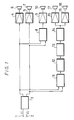
- the signals recorded on the magnetic tape and the video disc are the composite signals L T and R T as described above, there has been proposed a multi-channel stereo reproducing apparatus illustrated in Figure 1.
- the apparatus comprising left and right composite signal input terminals 1 and 2 to which the left and right composite signals L T and R T are supplied.
- the terminals 1 and 2 are connected to the input side of a balancing circuit 3 which produces left and right composite signals L T and R T which are so balanced as to localize an acoustic image normally.
- the outputs of the balancing circuit 3 are connected through amplifiers 4 and 5 to left and right front loudspeakers 6 and 7 which respectively reproduce the left and right composite signals L T and R T supplied to the terminals 1 and 2.
- the outputs of the balancing circuit 3 are connected to the input of a mixing circuit 8 which generates the sum signal L T +R T .
- the output of the mixing circuit 8 is connected through an amplifier 9 to a centre front loudspeaker 10 which reproduces the sum signal L T + R T developed at the output of the mixing circuit 8.
- the outputs of the balancing circuit 3 are connected to the input of a subtracting circuit 11 which generates the left and right composite signals L T and R T from which the monaural components are removed.
- the output of the subtracting circuit 11 is connected to the input of a delay circuit 12 which generates at its output side a delayed difference signal ⁇ t(L T -R T ), delayed by a predetermined time.
- the output of the delay circuit 12 is connected to the input of a low-pass filter 13 for passing therethrough a signal of a low frequency band, and the filter 13 generates at its output the delayed difference signal ⁇ t(L T -R T ) in which a clock pulse component resulting from passing the signal through the delay circuit 12 has been removed, and frequencies higher than a predetermined frequency are removed, so as to balance the low frequency component which is deficient in the difference signal L T -R T .
- the output of the low-pass filter 13 is connected to the input of a de-emphasis circuit 14 which attenuates the high frequency component of the delayed difference signal ⁇ t(L T -R T ) higher than 1 kHz, thus producing a delayed difference signal ⁇ t(L T -R T ) in which the total frequency characteristic of the rear signal B of which the high frequency component higher than 1 kHz has been emphasized is made flat.
- the output of the de-emphasis circuit 14 is connected through amplifiers 15 and 16 to left and right rear loudspeakers 17 and 18 by which the delayed difference signal ⁇ t(L T -R T ) in which the frequency characteristic of the rear signal B is made flat, is reproduced.
- the left and right composite signals L T and R T are reproduced from the left and right front loudspeakers 6 and 7, the sum signal L T +R T is reproduced from the centre front loudspeaker 10 and the delayed difference signal ⁇ t(L T -R T ) is reproduced from the left and right rear loudspeakers 17 and 18. Consequently, the sound effect is enhanced to produce good stereo presence.
- Japanese patent specification JP-A-54/62801 (GB-A-2 006 583)
- Japanese patent specification JP-A-49/120201 discloses a low-pass filter which can be selectively by-passed in a 2-channel or 4-channel stereo mode apparatus.
- the output of the low-pass filter 13 is connected to the input of the de-emphasis circuit 14 and to one fixed contact 19a of a change-over switch 19.
- the de-emphasis circuit 14 is modified to de-emphasize the high frequency component of the audio signal pre-emphasized by the modified B-type Dolby system, thereby to make the total frequency characteristic flat.
- the frequency characteristic of the de-emphasis circuit 14 may be such that when the signal level is about 30 dB, a signal level of a signal higher than about 4 kHz is emphasized by 5dB.
- the output of the de-emphasis circuit 14 is connected to the other fixed contact 19b of the switch 19, and a movable contact 19c thereof is connected through the amplifiers 15 and 16 to the left and right rear loudspeakers 17 and 18, whereby the de-emphasis circuit 14 can be by-passed, if necessary. Otherwise the arrangement is as shown in Figure 2.
- the left composite signal L T L F +F/2+B/2 is reproduced from the left front loudspeaker 6
- the delayed difference signal ⁇ t(L T -R T ) ⁇ t(L F -R F +B) is reproduced from the left and right rear loudspeakers 17 and 18.
- the movable contact 19c engages one fixed contact 19a to by-pass the de-emphasis circuit 14, thereby directly connecting the output of the low-pass filter 13 to the amplifiers 15 and 16, without attenuating the high frequency component of the delayed difference signal t(L F -R F ) obtained at the output of the low-pass filter 13, this delayed difference signal ⁇ t(L F -R F) can be reproduced.
- the delayed difference signal ⁇ t(L F -R F ) is reproduced together with the left front signal L F , the right front signal R F and the sum signal L F +R F , it is well known that stereo presence can be increased and hence the atmosphere of a concert hall or cinema can be obtained.
- the invention is applied to a multi-channel stereo reproducing apparatus for reproducing a recording medium on which a multi-channel stereo signal in which the rear signal B has been pre-emphasized by the modified B-type Dolby system is recorded
- the invention is not limited to this, but can be applied to a multi-channel stereo reproducing apparatus for reproducing a recording medium on which a signal pre-emphasized by another noise reduction system has been recorded, or an apparatus in which the above delay circuit is formed of a digital circuit comprising an A/D converter and a D/A converter.
Abstract
Description
- This invention relates to multi-channel stereo reproducing apparatus.
- When a film is shown in a cinema, the audio signal is generally reproduced by means of a Dolby surround-phonic 4-channel stereo reproducing system, so as to produce realistic sound.
- When a cinema film is made, a video signal is recorded, and at the same time left front sound, right front sound, centre front sound and rear sound are respectively recorded. In this case, a left front signal LF, a right front signal RF, a centre front signal F and a rear signal B are respectively encoded and recorded. To improve the signal-to-noise (S/N) ratio of the rear signal B, there is employed a so-called modified B-type Dolby system, in which a high frequency component of frequency higher than 1 kHz is emphasized by a predetermined amount. Figure 3 shows a frequency vs. response characteristics where the recording level is at 0 dB, -10 dB, -20 dB and -30 dB in this modified B-type Dolby system.
- The left front signal LF, the right front signal RF, the centre front signal F and the rear signal B are then further encoded to form a left composite signal LT and a right composite signal RT which are respectively expressed as


- Magnetic tapes and video discs of the screen music or the motion picture itself are also available on the market. In this case, since the signals recorded on the magnetic tape and the video disc are the composite signals LT and RT as described above, there has been proposed a multi-channel stereo reproducing apparatus illustrated in Figure 1.
- The apparatus comprising left and right composite
signal input terminals terminals balancing circuit 3 which produces left and right composite signals LT and RT which are so balanced as to localize an acoustic image normally. - The outputs of the
balancing circuit 3 are connected through amplifiers 4 and 5 to left and rightfront loudspeakers terminals - Also, the outputs of the
balancing circuit 3 are connected to the input of a mixing circuit 8 which generates the sum signal LT+RT. The output of the mixing circuit 8 is connected through anamplifier 9 to acentre front loudspeaker 10 which reproduces the sum signal LT + RT developed at the output of the mixing circuit 8. - Further, the outputs of the
balancing circuit 3 are connected to the input of asubtracting circuit 11 which generates the left and right composite signals LT and RT from which the monaural components are removed. The output of thesubtracting circuit 11 is connected to the input of adelay circuit 12 which generates at its output side a delayed difference signal Δt(LT-RT), delayed by a predetermined time. Thus, a front localization impression and a sound field widening impression are obtained. The output of thedelay circuit 12 is connected to the input of a low-pass filter 13 for passing therethrough a signal of a low frequency band, and thefilter 13 generates at its output the delayed difference signal Δt(LT-RT) in which a clock pulse component resulting from passing the signal through thedelay circuit 12 has been removed, and frequencies higher than a predetermined frequency are removed, so as to balance the low frequency component which is deficient in the difference signal LT-RT. The output of the low-pass filter 13 is connected to the input of ade-emphasis circuit 14 which attenuates the high frequency component of the delayed difference signal Δt(LT-RT) higher than 1 kHz, thus producing a delayed difference signal Δt(LT-RT) in which the total frequency characteristic of the rear signal B of which the high frequency component higher than 1 kHz has been emphasized is made flat. The output of thede-emphasis circuit 14 is connected throughamplifiers rear loudspeakers - In this apparatus, the left and right composite signals LT and RT are reproduced from the left and right
front loudspeakers centre front loudspeaker 10 and the delayed difference signal Δt(LT-RT) is reproduced from the left and rightrear loudspeakers - However, with this apparatus, when reproducing a recording medium, such as a record disc or a cassette tape on which only the standard 2-channel stereo signal formed of the left front signal LF and the right front signal RF are recorded, since the delayed difference signal Δt(LF+RF) from the
delay circuit 12 passes through thede-emphasis circuit 14, its high frequency component higher than 1 KHz is attenuated. Then, the delayed difference signal Δt(LF-RF) in which the high frequency component has been attenuated is reproduced from the left and rightrear loudspeakers - A different sound system for cinema use is disclosed in Japanese patent specification JP-A-54/62801 (GB-A-2 006 583), while Japanese patent specification JP-A-49/120201 discloses a low-pass filter which can be selectively by-passed in a 2-channel or 4-channel stereo mode apparatus.
- According to the present invention there is provided a multi-channel stereo reproducing apparatus for reproducing a recording medium wherein a left front signal LF, a right front signal RF, a centre front signal F and a rear signal B have been encoded to form left and right composite recorded signals LT and RT, where


a reproducing circuit for reproducing said left composite signal LT, said right composite signal RT and a sum signal LT+RT; and
a reproducing circuit for reproducing a difference signal LT-RT through a delay circuit and a de-emphasis circuit;
characterized by:
means for by-passing said de-emphasis circuit when reproducing a recording medium on which a 2-channel stereo signal formed of only said left and right front signals LF and RF is recorded. - The invention will now be described by way of example with reference to the accompanying drawings, throughout which like parts are referred to by like references, and in which:
- Figure 1 is a block diagram of a previously proposed multi-channel stereo reproducing apparatus;
- Figure 2 is a block diagram of an embodiment of multi-channel stereo reproducing apparatus according to the present invention; and
- Figure 3 is a frequency vs. response graph.
- In the embodiment shown in Figure 2, the output of the low-
pass filter 13 is connected to the input of thede-emphasis circuit 14 and to one fixed contact 19a of a change-over switch 19. In this case, thede-emphasis circuit 14 is modified to de-emphasize the high frequency component of the audio signal pre-emphasized by the modified B-type Dolby system, thereby to make the total frequency characteristic flat. The frequency characteristic of thede-emphasis circuit 14 may be such that when the signal level is about 30 dB, a signal level of a signal higher than about 4 kHz is emphasized by 5dB. - The output of the
de-emphasis circuit 14 is connected to the other fixedcontact 19b of the switch 19, and a movable contact 19c thereof is connected through theamplifiers rear loudspeakers circuit 14 can be by-passed, if necessary. Otherwise the arrangement is as shown in Figure 2. - In this embodiment, when the movable contact 19c engages the fixed
contact 19b, the circuit arrangement is effectively the same as that of Figure 2. Accordingly, the left front signal LF, the right front signal RF, the centre front signal F and the rear signal B have been encoded respectively to form the left and right composite signals LT and RT which are respectively expressed as


left front loudspeaker 6, the right composite signal
right front loudspeaker 7, the sum signal
centre front loudspeaker 10, and the delayed difference signal
rear loudspeakers 

de-emphasis circuit 14 and such that its total frequency characteristic relative to the rear signal B is made flat, the sound effect can be enhanced to produce stereo presence as obtained in a concert hall or cinema. - With this embodiment, it is possible to reproduce the standard 2-channel stereo signal formed only of the left and right front signal LF and RF, in which the centre front signal F and the rear signal B are not present. In this case, when the left and right front signals LF and RF are supplied to the left and right composite
signal input terminals right loudspeakers centre front loudspeaker 10, and the delayed difference signal Δt(LF-RF) is reproduced from therear loudspeakers de-emphasis circuit 14, thereby directly connecting the output of the low-pass filter 13 to theamplifiers pass filter 13, this delayed difference signal Δt(LF-RF) can be reproduced. When the delayed difference signal Δt(LF-RF) is reproduced together with the left front signal LF, the right front signal RF and the sum signal LF+RF, it is well known that stereo presence can be increased and hence the atmosphere of a concert hall or cinema can be obtained. - While in the above embodiment, the invention is applied to a multi-channel stereo reproducing apparatus for reproducing a recording medium on which a multi-channel stereo signal in which the rear signal B has been pre-emphasized by the modified B-type Dolby system is recorded, the invention is not limited to this, but can be applied to a multi-channel stereo reproducing apparatus for reproducing a recording medium on which a signal pre-emphasized by another noise reduction system has been recorded, or an apparatus in which the above delay circuit is formed of a digital circuit comprising an A/D converter and a D/A converter.
Claims (5)
- A multi-channel stereo reproducing apparatus for reproducing a recording medium wherein a left front signal LF, a right front signal RF, a centre front signal F and a rear signal B have been encoded to form left and right composite recorded signals LT and RT, where


a reproducing circuit (3, 8) for reproducing said left composite signal LT, said right composite signal RT and a sum signal LT+RT; and
a reproducing circuit (3, 11) for reproducing a difference signal LT-RT through a delay circuit (12) and a de-emphasis circuit (14);
characterized by:
means (19) for by-passing said de-emphasis circuit (14) when reproducing a recording medium on which a 2-channel stereo signal formed of only said left and right front signals LF and RF is recorded. - Apparatus according to claim 1 wherein said by-pass means (19) comprises a change-over switch (19) having a pair of fixed contacts (19a, 19b) and a movable contact (19c), said pair of fixed contacts (19a, 19b) being respectively connected to the input and output sides of said de-emphasis circuit (14), and said movable contact (19c) being connected to the output side of said reproducing circuit (3, 11).
- Apparatus according to claim 2 wherein said de-emphasis circuit (14) has a frequency characteristic in which a signal level of a high frequency is emphasized in response to a signal level of said difference signal LT-RT.
- Apparatus according to claim 3 wherein said frequency characteristic is such that when the signal level is about 30 dB, a signal level of a signal higher than about 4 kHz is emphasized by 5 dB.
- Apparatus according to claim 1 wherein said delay circuit (12) comprises a digital circuit having an A/D converter and a D/A converter.
Applications Claiming Priority (2)
| Application Number | Priority Date | Filing Date | Title |
|---|---|---|---|
| JP60263158A JPS62122500A (en) | 1985-11-22 | 1985-11-22 | Multi-channel stereo reproducing device |
| JP263158/85 | 1985-11-22 |
Publications (3)
| Publication Number | Publication Date |
|---|---|
| EP0249640A1 EP0249640A1 (en) | 1987-12-23 |
| EP0249640A4 EP0249640A4 (en) | 1989-09-19 |
| EP0249640B1 true EP0249640B1 (en) | 1993-02-24 |
Family
ID=17385595
Family Applications (1)
| Application Number | Title | Priority Date | Filing Date |
|---|---|---|---|
| EP86906934A Expired - Lifetime EP0249640B1 (en) | 1985-11-22 | 1986-11-18 | Multi-channel stereo reproducing apparatus |
Country Status (8)
| Country | Link |
|---|---|
| US (1) | US4807217A (en) |
| EP (1) | EP0249640B1 (en) |
| JP (1) | JPS62122500A (en) |
| KR (1) | KR950008651B1 (en) |
| AU (1) | AU595845B2 (en) |
| DE (1) | DE3687836T2 (en) |
| HK (1) | HK95895A (en) |
| WO (1) | WO1987003449A1 (en) |
Families Citing this family (22)
| Publication number | Priority date | Publication date | Assignee | Title |
|---|---|---|---|---|
| JPS63183495A (en) * | 1987-01-27 | 1988-07-28 | ヤマハ株式会社 | Sound field controller |
| EP0323830B1 (en) * | 1988-01-06 | 1995-03-29 | LucasArts Entertainment Company | Surround-sound system |
| US5222059A (en) * | 1988-01-06 | 1993-06-22 | Lucasfilm Ltd. | Surround-sound system with motion picture soundtrack timbre correction, surround sound channel timbre correction, defined loudspeaker directionality, and reduced comb-filter effects |
| US5043970A (en) * | 1988-01-06 | 1991-08-27 | Lucasarts Entertainment Company | Sound system with source material and surround timbre response correction, specified front and surround loudspeaker directionality, and multi-loudspeaker surround |
| JPH01126700U (en) * | 1988-02-12 | 1989-08-30 | ||
| JPH0228200U (en) * | 1988-08-12 | 1990-02-23 | ||
| KR910008762B1 (en) * | 1988-12-07 | 1991-10-19 | 삼성전자 주식회사 | Circuit for generating 4-channel surround sound of speaker system |
| JPH0623119Y2 (en) * | 1989-01-24 | 1994-06-15 | パイオニア株式会社 | Surround stereo playback device |
| US5594800A (en) * | 1991-02-15 | 1997-01-14 | Trifield Productions Limited | Sound reproduction system having a matrix converter |
| JPH08502867A (en) * | 1992-10-29 | 1996-03-26 | ウィスコンシン アラムニ リサーチ ファンデーション | Method and device for producing directional sound |
| NL9401860A (en) * | 1994-11-08 | 1996-06-03 | Duran Bv | Loudspeaker system with controlled directivity. |
| US5708719A (en) * | 1995-09-07 | 1998-01-13 | Rep Investment Limited Liability Company | In-home theater surround sound speaker system |
| US6118876A (en) * | 1995-09-07 | 2000-09-12 | Rep Investment Limited Liability Company | Surround sound speaker system for improved spatial effects |
| US5930370A (en) * | 1995-09-07 | 1999-07-27 | Rep Investment Limited Liability | In-home theater surround sound speaker system |
| US5850455A (en) * | 1996-06-18 | 1998-12-15 | Extreme Audio Reality, Inc. | Discrete dynamic positioning of audio signals in a 360° environment |
| US6154549A (en) * | 1996-06-18 | 2000-11-28 | Extreme Audio Reality, Inc. | Method and apparatus for providing sound in a spatial environment |
| US6198826B1 (en) * | 1997-05-19 | 2001-03-06 | Qsound Labs, Inc. | Qsound surround synthesis from stereo |
| JP3573981B2 (en) * | 1998-11-17 | 2004-10-06 | パイオニア株式会社 | Integrated circuit for audio signal processing |
| US6925426B1 (en) | 2000-02-22 | 2005-08-02 | Board Of Trustees Operating Michigan State University | Process for high fidelity sound recording and reproduction of musical sound |
| AUPQ938000A0 (en) * | 2000-08-14 | 2000-09-07 | Moorthy, Surya | Method and system for recording and reproduction of binaural sound |
| RU2600987C2 (en) * | 2011-02-22 | 2016-10-27 | Басф Се | Polymers based on glycerin carbonate and amine |
| CN104269165A (en) * | 2014-09-10 | 2015-01-07 | 韩熠 | Guitar digital delay effector |
Family Cites Families (10)
| Publication number | Priority date | Publication date | Assignee | Title |
|---|---|---|---|---|
| JPS49120201U (en) * | 1972-09-25 | 1974-10-15 | ||
| JPS5190901U (en) * | 1975-01-20 | 1976-07-21 | ||
| US3971890A (en) * | 1975-02-10 | 1976-07-27 | Cbs Inc. | Method and apparatus for quadraphonic enhancement of stereophonic signals |
| JPS5190801U (en) * | 1976-01-08 | 1976-07-21 | ||
| GB2006583B (en) * | 1977-10-14 | 1982-04-28 | Dolby Lab Licensing Corp | Multi-channel sound systems |
| US4303800A (en) * | 1979-05-24 | 1981-12-01 | Analog And Digital Systems, Inc. | Reproducing multichannel sound |
| US4532647A (en) * | 1981-08-19 | 1985-07-30 | John C. Bogue | Automatic dimension control for a directional enhancement system |
| US4525855A (en) * | 1981-08-27 | 1985-06-25 | John C. Bogue | Variable rate and variable limit dimension controls for a directional enhancement system |
| JPS5963813A (en) * | 1982-10-02 | 1984-04-11 | Kazuyoshi Kanematsu | Delay circuit |
| US4577305A (en) * | 1983-03-14 | 1986-03-18 | Dolby Laboratories Licensing Corporation | Stereophonic motion picture photographic sound-tracks compatible with different sound projection formats and record and playback apparatus therefore |
-
1985
- 1985-11-22 JP JP60263158A patent/JPS62122500A/en active Pending
-
1986
- 1986-11-18 EP EP86906934A patent/EP0249640B1/en not_active Expired - Lifetime
- 1986-11-18 WO PCT/JP1986/000588 patent/WO1987003449A1/en active IP Right Grant
- 1986-11-18 US US07/086,631 patent/US4807217A/en not_active Expired - Lifetime
- 1986-11-18 AU AU66273/86A patent/AU595845B2/en not_active Ceased
- 1986-11-18 KR KR1019870700633A patent/KR950008651B1/en not_active IP Right Cessation
- 1986-11-18 DE DE8686906934T patent/DE3687836T2/en not_active Expired - Fee Related
-
1995
- 1995-06-15 HK HK95895A patent/HK95895A/en not_active IP Right Cessation
Also Published As
| Publication number | Publication date |
|---|---|
| AU6627386A (en) | 1987-07-01 |
| KR950008651B1 (en) | 1995-08-03 |
| AU595845B2 (en) | 1990-04-12 |
| WO1987003449A1 (en) | 1987-06-04 |
| EP0249640A1 (en) | 1987-12-23 |
| KR880701058A (en) | 1988-04-22 |
| DE3687836D1 (en) | 1993-04-01 |
| DE3687836T2 (en) | 1993-07-22 |
| HK95895A (en) | 1995-06-23 |
| EP0249640A4 (en) | 1989-09-19 |
| US4807217A (en) | 1989-02-21 |
| JPS62122500A (en) | 1987-06-03 |
Similar Documents
| Publication | Publication Date | Title |
|---|---|---|
| EP0249640B1 (en) | Multi-channel stereo reproducing apparatus | |
| EP0404117B1 (en) | Surround-sound system | |
| JP2755208B2 (en) | Sound field control device | |
| US20040005066A1 (en) | Apparatus and method for synthesizing pseudo-stereophonic outputs from a monophonic input | |
| US5222059A (en) | Surround-sound system with motion picture soundtrack timbre correction, surround sound channel timbre correction, defined loudspeaker directionality, and reduced comb-filter effects | |
| US5261005A (en) | Sound field control device | |
| US3761628A (en) | Stereo-quadraphonic matrix system with matrix or discrete sound reproduction capability | |
| US6850622B2 (en) | Sound field correction circuit | |
| US5189703A (en) | Timbre correction units for use in sound systems | |
| JPH08265899A (en) | Surround signal processor and video and sound reproducing device | |
| CA1100881A (en) | Sound system apparatus and format | |
| US6711270B2 (en) | Audio reproducing apparatus | |
| JP3700254B2 (en) | Video / audio playback device | |
| EP0323830B1 (en) | Surround-sound system | |
| JPH1132398A (en) | Duplication system, edit system and method for recording recording medium | |
| JPH0332160Y2 (en) | ||
| JP3111465B2 (en) | Audio signal playback device | |
| JPH0328638Y2 (en) | ||
| JPH10191203A (en) | Sound reproduction circuit | |
| JPH0328637Y2 (en) | ||
| JPH11113084A (en) | Acoustic recorder with stereophonic acoustic recording function and its method | |
| Nakahara | Multichannel Monitoring Tutorial Booklet | |
| JPS5914120A (en) | Magnetic sound recording and reproducing device | |
| JPH03266598A (en) | Acoustic circuit | |
| JPS6134319B2 (en) |
Legal Events
| Date | Code | Title | Description |
|---|---|---|---|
| PUAI | Public reference made under article 153(3) epc to a published international application that has entered the european phase |
Free format text: ORIGINAL CODE: 0009012 |
|
| 17P | Request for examination filed |
Effective date: 19870729 |
|
| AK | Designated contracting states |
Kind code of ref document: A1 Designated state(s): DE FR GB NL |
|
| A4 | Supplementary search report drawn up and despatched |
Effective date: 19890919 |
|
| 17Q | First examination report despatched |
Effective date: 19910807 |
|
| GRAA | (expected) grant |
Free format text: ORIGINAL CODE: 0009210 |
|
| AK | Designated contracting states |
Kind code of ref document: B1 Designated state(s): DE FR GB NL |
|
| REF | Corresponds to: |
Ref document number: 3687836 Country of ref document: DE Date of ref document: 19930401 |
|
| ET | Fr: translation filed | ||
| PLBE | No opposition filed within time limit |
Free format text: ORIGINAL CODE: 0009261 |
|
| STAA | Information on the status of an ep patent application or granted ep patent |
Free format text: STATUS: NO OPPOSITION FILED WITHIN TIME LIMIT |
|
| 26N | No opposition filed | ||
| PGFP | Annual fee paid to national office [announced via postgrant information from national office to epo] |
Ref country code: NL Payment date: 19961128 Year of fee payment: 11 |
|
| PG25 | Lapsed in a contracting state [announced via postgrant information from national office to epo] |
Ref country code: NL Free format text: LAPSE BECAUSE OF NON-PAYMENT OF DUE FEES Effective date: 19980601 |
|
| NLV4 | Nl: lapsed or anulled due to non-payment of the annual fee |
Effective date: 19980601 |
|
| PGFP | Annual fee paid to national office [announced via postgrant information from national office to epo] |
Ref country code: FR Payment date: 20011113 Year of fee payment: 16 |
|
| PGFP | Annual fee paid to national office [announced via postgrant information from national office to epo] |
Ref country code: GB Payment date: 20011121 Year of fee payment: 16 |
|
| PGFP | Annual fee paid to national office [announced via postgrant information from national office to epo] |
Ref country code: DE Payment date: 20011203 Year of fee payment: 16 |
|
| REG | Reference to a national code |
Ref country code: GB Ref legal event code: IF02 |
|
| PG25 | Lapsed in a contracting state [announced via postgrant information from national office to epo] |
Ref country code: GB Free format text: LAPSE BECAUSE OF NON-PAYMENT OF DUE FEES Effective date: 20021118 |
|
| PG25 | Lapsed in a contracting state [announced via postgrant information from national office to epo] |
Ref country code: DE Free format text: LAPSE BECAUSE OF NON-PAYMENT OF DUE FEES Effective date: 20030603 |
|
| GBPC | Gb: european patent ceased through non-payment of renewal fee | ||
| PG25 | Lapsed in a contracting state [announced via postgrant information from national office to epo] |
Ref country code: FR Free format text: LAPSE BECAUSE OF NON-PAYMENT OF DUE FEES Effective date: 20030731 |
|
| REG | Reference to a national code |
Ref country code: FR Ref legal event code: ST |