EP0248461B2 - Dispositif pour indiquer l'état de charge d'une batterie - Google Patents
Dispositif pour indiquer l'état de charge d'une batterie Download PDFInfo
- Publication number
- EP0248461B2 EP0248461B2 EP87200844A EP87200844A EP0248461B2 EP 0248461 B2 EP0248461 B2 EP 0248461B2 EP 87200844 A EP87200844 A EP 87200844A EP 87200844 A EP87200844 A EP 87200844A EP 0248461 B2 EP0248461 B2 EP 0248461B2
- Authority
- EP
- European Patent Office
- Prior art keywords
- battery
- charging
- value
- time
- adjusting means
- Prior art date
- Legal status (The legal status is an assumption and is not a legal conclusion. Google has not performed a legal analysis and makes no representation as to the accuracy of the status listed.)
- Expired - Lifetime
Links
Images


Classifications
-
- H—ELECTRICITY
- H02—GENERATION; CONVERSION OR DISTRIBUTION OF ELECTRIC POWER
- H02J—ELECTRIC POWER NETWORKS; CIRCUIT ARRANGEMENTS OR SYSTEMS FOR SUPPLYING OR DISTRIBUTING ELECTRIC POWER; SYSTEMS FOR STORING ELECTRIC ENERGY
- H02J7/00—Circuit arrangements for charging or discharging batteries or for supplying loads from batteries
- H02J7/90—Regulation of charging or discharging current or voltage
- H02J7/94—Regulation of charging or discharging current or voltage in response to battery current
- H02J7/947—Regulation of charging or discharging current or voltage in response to battery current in response to integrated charge or discharge current
-
- G—PHYSICS
- G01—MEASURING; TESTING
- G01R—MEASURING ELECTRIC VARIABLES; MEASURING MAGNETIC VARIABLES
- G01R31/00—Arrangements for testing electric properties; Arrangements for locating electric faults; Arrangements for electrical testing characterised by what is being tested not provided for elsewhere
- G01R31/36—Arrangements for testing, measuring or monitoring the electrical condition of accumulators or electric batteries, e.g. capacity or state of charge [SoC]
- G01R31/3644—Constructional arrangements
- G01R31/3648—Constructional arrangements comprising digital calculation means, e.g. for performing an algorithm
-
- H—ELECTRICITY
- H02—GENERATION; CONVERSION OR DISTRIBUTION OF ELECTRIC POWER
- H02J—ELECTRIC POWER NETWORKS; CIRCUIT ARRANGEMENTS OR SYSTEMS FOR SUPPLYING OR DISTRIBUTING ELECTRIC POWER; SYSTEMS FOR STORING ELECTRIC ENERGY
- H02J7/00—Circuit arrangements for charging or discharging batteries or for supplying loads from batteries
- H02J7/90—Regulation of charging or discharging current or voltage
- H02J7/94—Regulation of charging or discharging current or voltage in response to battery current
-
- Y—GENERAL TAGGING OF NEW TECHNOLOGICAL DEVELOPMENTS; GENERAL TAGGING OF CROSS-SECTIONAL TECHNOLOGIES SPANNING OVER SEVERAL SECTIONS OF THE IPC; TECHNICAL SUBJECTS COVERED BY FORMER USPC CROSS-REFERENCE ART COLLECTIONS [XRACs] AND DIGESTS
- Y10—TECHNICAL SUBJECTS COVERED BY FORMER USPC
- Y10S—TECHNICAL SUBJECTS COVERED BY FORMER USPC CROSS-REFERENCE ART COLLECTIONS [XRACs] AND DIGESTS
- Y10S320/00—Electricity: battery or capacitor charging or discharging
- Y10S320/18—Indicator or display
- Y10S320/21—State of charge of battery
Definitions
- the invention relates to a device for indicating the charge status of a battery during charging and/or discharging comprising: a power-supply circuit for charging the battery and/or energizing a load (R L ); clock means for generating clock pulses during charging and/or discharging of the battery; computing means for computing the charge status on the basis of the generated clock pulses; and indicator means for indicating the computed charge status.
- Such a device is suitable for use in rechargeable apparatuses, in particular in rechargeable electronic shavers.
- Such a device is known from CH-A-648 936.
- the known apparatus contains a current measuring device, placed in series with the battery and the load. At regular intervals the current flowing through the measuring device is measured and stored in a storage and calculation device. The length of the intervals is measured using a clock, which generates regular clock pulses. By multiplication of the momentaneous strength of the current and the length of the interval between two measurements an approximation is obtained of the amount of charge that is extracted from the battery. This amount of charge is subtracted from the nominal charge capacity of the battery and the outcome of the subtraction is presented as the remaining charge left in the battery.
- the nominal capacity may be overestimated with respect to the actual capacity and the battery runs out before the device has calculated and indicated zero remaining charge. If this situation is detected, the reduced actual capacity is derived from the fact that the battery is empty and subsequently stored in the storage and calculation device to replace the nominal capacity, so that during a new discharge cycle the device correctly indicates the charge status using the revised capacity and an unexpected running out of the battery is avoided.
- a disadvantage of the known device is that for determining the charge status it is necessary to connect current measuring means in series with the load between the battery terminals.
- the known device is not suitable for use in, for example, a rechargeable electronic shaver, in which the load is constituted by a motor.
- the current measuring means should have such a low resistance value that obtaining a sensible output from the current measuring device presents major problems.
- the nominal battery capacity is only adapted to the actual battery capacity when the battery is exhausted. So at a moment the user is confronted with an apparatus that is unexpectedly not functioning.
- a device for indicating the charge status of a battery.
- this device measures the charging and discharging currents by means of a resistor connected in series with the battery.
- the voltage across this resistor is amplified and then integrated, the gain and the integration constant during discharging being different from those during charging of the battery.
- the integrated voltage is compared with a reference voltage and each time that this reference voltage is reached a pulse is generated. These pulses are supplied to a counter whose count is displayed by means of an indicator which indicates the charge status of the battery.
- a warning signal is generated as soon as a specific count is reached and after a certain time the load is disconnected from the battery to preclude complete discharging of the battery.
- the charging circuit is disconnected when a maximum count is reached to prevent the battery from becoming overcharged.
- a device which device comprises a clock generating clock-pulses during the discharging of a battery.
- the known device is intended to test the charge capacity of a battery.
- the clock-means generates clock-pulses which are added to measure the passing of time.
- the battery voltage is checked, and if it falls below a threshold value before a predetermined period of time has passed the amount in which the battery capacity has deteriorated can be accessed by the number of clock-pulses counted. If, after passing of the predetermined period of time, the threshold level has not been reached, the condition of the battery is concluded to be satisfactory.
- This known device does not compute and indicate the charge status of the battery during discharging.
- a device of the type defined in the opening paragraph is characterized in that: the computing means comprise: first adjusting means for adjusting a discharging time of the battery to a first value during discharging of the battery by the load and/or second adjusting means for adjusting a charging time of the battery to a second value during charging of the battery by the power-supply circuit under no-load condition, and time-measuring means for determining, on the basis of the generated clock pulses alone, the ratio between the elapsed discharging time and said first value representing the adjusted discharging time and/or for determining the ratio between the elapsed charging time and said second value representing the adjusted charging time, which ratios represent the computed charge status, and in that the device further comprises: detection means for detecting at least one actual charge status of the battery during virtually every discharging and/or virtually every charging cycle
- the operation of the device in accordance with the invention does not require the measurement of charging and discharging currents but is based on an adjusted and initially nominal discharging time and/or charging time for a given capacity of the battery.
- the charge status is determined by measuring the elapsed discharging time and/or charging time and expressing them as a fraction of the nominal discharging time and/or charging time.
- the computed charge status is compared with a measured actual charge status during the discharging and/or charging of the battery. In the case of a difference the computed charge status is corrected and the adjusted discharging or charging time is also corrected, so that during the next discharging or charging cycle of the battery the computed charge status will be better in conformity with the actual charge status.
- the device in accordance with the invention is therefore suitable for indicating the charge status either during discharging or discharging of the battery and also for indicating the charge status both during discharging and charging of the battery.
- the computed charge status is compared with an actual charge status and, if necessary, corrected not only during discharging but preferably also at a specific instant during charging of the battery.
- the battery is charged very rapidly, for example in a few minutes, it may be less interesting to the user to have information on the charge status of the battery during charging. In such a case it is adequate to compare the computed charge status with an actual charge status of the battery and, if necessary, correct it only during discharging.
- One embodiment may be characterized in that the detection means for detecting said at least one actual charge status during discharging of the battery comprise a first detection device for detecting a decrease of the battery voltage below a reference voltage.
- the detection means for detecting said at least one actual charge status during charging of the battery comprise a second detection device for detecting the substantially fully-charged condition of the battery.
- the second detection device comprises a device for detecting a battery-voltage decrease which occurs when the battery is in the substantially fully charged condition.
- the second detection device comprises a device for detecting whether the battery voltage is equal to a reference voltage.
- the charge status may also be calculated and adapted in a number of other situations, in order to ensure that the computed charge status agrees as far as possible with the actual charge status.
- the charge status may also be computed in the situation in which the load is energized by the power-supply circuit, when also a specific charging current may be supplied to the battery.
- the computing means further comprise third adjusting means for adjusting a charging time of the battery to a third value during charging of the battery by the power-supply circuit in its loaded condition.
- the charge status can be calculated if the device in another embodiment is characterized in that the computing means further comprise fourth adjusting means for adjusting a charging time of the battery to a fourth value during charging of the battery by the power-supply circuit in the no-load condition and when the battery is in the substantially fully charged condition.
- the charge status may also be computed in the case of self-discharging of the battery.
- the device is then characterized in that the computing means further comprise fifth adjusting means for adjusting a discharging time of the battery to a fifth value during discharging of the battery when the power-supply circuit and the load are inoperative.
- the device in another embodiment may be characterized in that the power-supply circuit is adapted to supply a charging current to the battery for a fraction of the charging time which charging current is larger than the charging current during the remainder of the charging time of the battery, and in that the computing means further comprise sixth adjusting means for adjusting a charging time of the battery to a sixth value during charging of the battery with an increased charging current when the load is inoperative and the battery is substantially empty.
- each of the adjusting means comprises a memory device for storing the adjusted value of the relevant adjusting means
- the time-measuring means comprise: an adjustable frequency divider for dividing the frequency of the clock pulses from the clock means depending on the value stored in the relevant adjusting means, and a memory device having a fixed number of storage locations for the storage of the number of clock pulses supplied by the frequency divider, which number represents the computed charge status.
- the charge status is determined by filling a non-volatile memory with clock pulses of variable frequency during charging and vacating this memory during discharging, the frequency of said clock pulses being dictated by the value stored in the relevant adjusting means and corrected by the correction means.
- first adjusting means comprise a first memory device for the storage of a first value, which represents the discharging time of the battery when discharged by the load
- second adjusting means comprise a second memory device for the storage of the second value, which represents the charging time of the battery by the power-supply circuit
- each of the other adjusting means comprises a memory device common to the first or second adjusting means, and means for connecting a fixed frequency divider in series with the programmable frequency divider.
- each of the adjusting means comprises a memory device for storing the adjusted value of the relevant adjusting means
- the time-measuring means comprise: a memory device whose number of storage locations is proportional to the value stored in the relevant adjusting means and a frequency divider for dividing the frequency of the clock pulses by a fixed number.
- the charge status is determined in that a variable memory, whose storage capacity is dictated by the value stored in the relevant adjusting means and corrected by the correction means, is filled with clock pulses of a fixed frequency during charging and is vacated with clock pulses of a fixed frequency during discharging.
- first adjusting means comprise a memory device for storing the first value
- second adjusting means comprise a memory device for storing the second value
- each of the other adjusting means comprises a memory device common to the first or the second adjusting means for connecting a second fixed frequency divider in series with the said fixed frequency divider.
- the indicator means of the device in accordance with the invention suitably comprises a passive electro-optical display device, in particular a liquid-crystal display device.
- Fig. 1 is the basic diagram of a device for indicating the charge status of a battery.
- the device comprises a power-supply circuit 1 with terminals 2 and 3 for applying a mains voltage, which may be an alternating voltage or a direct voltage.
- the power-supply circuit is, for example, a switched-mode power supply as known from British Patent Specification 2,000,394 or European Patent Application 30,026.
- a battery 4 is connected to the output of the power-supply circuit.
- battery is to be understood to mean an assembly of one or more cells.
- the battery 4 comprises two nickel-cadmium cells connected in series.
- a load R L can be connected in parallel with the battery 4.
- This load R L is, for example the motor of a dry-shaver.
- a device 7 is connected in parallel with the battery 4, to detect an actual charge status when the battery 4 is discharged.
- the device 7 detects for example whether the battery 4 is nearly empty by detecting a voltage level which corresponds to, for example, ten per cent of the nominal battery capacity.
- the device 7 comprises, for example, a comparator, which compares the battery voltage derived therefrom. It is to be noted that such detection devices are known per se, for example from United States Patent Specification 4,536,757 and from European Patent Application 115,625.
- the power-supply circuit 1 When the mains voltage is applied and when the switch S1 is open the power-supply circuit 1 supplies the charging current for the battery 4, which condition will be referred to hereinafter as "battery charging”. If the power-supply circuit 1 is not connected to the mains and the switch S1 is closed, the battery 4 supplies the supply current to the load R L , which condition will be referred to hereinafter as “battery shaving".
- the device further comprises a number of means 8 to 15, whose supply voltages are furnished by the battery 4.
- the device comprises control means 8 which on the basis of a signal providing information on whether the switch S1 is closed or not and a signal providing information on whether the power-supply circuit 1 is connected to the mains or not determines whether the battery-charging mode or the battery-shaving mode obtains.
- the device also comprises computing means 9 comprising first adjusting means 10, second adjusting means 11 and time-measuring means 12.
- the first adjusting means 10 comprise a non-volatile and a volatile memory, the non-volatile memory containing a value, which dictates the nominal discharging time of the battery 4.
- the second adjusting means 11 only comprise a non-volatile memory, which stores a value dictating the nominal charging time of the battery 4.
- the value stored in the first or in the second adjusting means is applied to the time-measuring means 12.
- clock pulses are supplied to the time-measuring means 12 by clock means 13. From the number of clock pulses the time-measuring means 12 determine the fraction which the elapsed discharging and charging times form of the total discharging time and charging time stored in the adjusting means 10 and 11 respectively.
- the fractions as calculated by the computing means 9 are indicated by an indicator means 14, which may comprise any passive or active indicator means or a combination thereof.
- the relevant information may be represented in any form, for example alphanumerically or segmentarily.
- the indicator means may be constructed so as to indicate the charge status not only during operation of the device but also for a definite or indefinite time after switching-off of the device.
- the charge status of the battery may be indicated, for example, by an electro-optical indicator means during operation of the device and by an electro-acoustic indicator means after switching off.
- the electro-acoustic indicator means may produce, for example, a number of acoustic signals in conformity with the charge status of the battery. Obviously, it is also possible to indicate the charge status only after the device has been switched off.
- the value which is stored in the volatile memory of the adjusting means 10 and which defines the discharging time of the battery 4 is applied to the time-measuring means 12.
- said means 12 express the discharging time which has elapsed as a fraction of the adjusted discharging time of the battery 4. This fraction forms the calculated charge status which is indicated by the indicator means 14.
- the function as calculated by the computing means is also applied to the correction means 15.
- These means also receive a detection signal from the detection means 7, which, as mentioned above, detects when still a fraction of, say 10%, of the battery capacity is left during discharging of the battery 4. If for whatever reason the discharging current of the battery differs from the nominal discharging current, the residual fraction as calculated by the computing means 12 deviates from the actual residual fraction of the battery capacity as signalled by the detection means 7.
- the correction circuit 15 then corrects the fraction calculated by the computing means 12 and hence also the indication by the indicator means 14.
- the correction means 15 correct the value stored in the volatile memory of the adjusting means 10, which value determines the discharging time of the battery 4, in such a way that during the next discharge of the battery 4 the calculated charge status is better in conformity with the actual charge status of the battery 4.
- the detection means 7 may detect any other voltage level.
- the means 7 detect the voltage level corresponding to the fully discharged condition of the battery 4.
- the value which is stored in the adjusting means 11 by the control means 8 and which defines the nominal charging time of the battery 4 is applied to the time-mesauring means 12. If the fraction calculated by the time-measuring means 12 on the basis of the clock pulses from the clock means 13 is unity, i.e. after the adjusted charging time, the time-measuring means 12 generate a signal which stops the power-supply circuit 1. The indicator means 14 then indicates that the battery 4 is fully charged.
- a calculated and indicated charge status are compared in the above-described way with the actual charge status during discharging, the adjusted discharging time being each time corrected in such a way that the calculated and the actual charge status are better in conformity with each other during the next charging and discharging cycle.
- Fig. 2 shows an extension of the diagram of Fig. 1.
- the device does not only comprise a detection device 7 for detecting an actual charge status during discharging, but also a detection device 16 for detecting an actual charge status during charging of the battery 4.
- the detection device 16 comprises for example a means which detects whether the battery 4 is substantially fully charged. To achieve this several methods are known, such as detection of a specific battery voltage, detection of a maximum in the battery voltage by detecting a change of sign of the first derivative of the battery voltage with respect to time or by detecting a decrease of the battery voltage, detecting a change of sign of the second derivative of the battery voltage with respect to time or detecting a sudden temperature rise occurring when the battery is overcharged. Such methods are described in for example United States Patent Specification 4,392,101. Upon detection of the battery 4 being substantially fully charged the detection device 16 generates a signal which causes the power-supply circuit 1 to be disconnected.
- the second adjusting means like the first adjusting means 10 now comprise a non-volatile and a volatile memory, a value determining the nominal discharging time of the battery 4 being stored in the non-volatile memory.
- the value is transferred from the non-volatile memory into the volatile memory.
- the device operates in the same way as described with reference to Fig. 1.
- the value stored in the volatile memory of the adjusting means 11 which value determines the charging time of the battery 4
- the control means 8 On the basis of the clock pulses from the clock means 13 these means 12 express the elapsed charging time of the battery 4 as a fraction of the adjusted charging time of the battery 4. This fraction again forms the calculated charge status as indicated by the indicator means 14.
- the correction circuit 15 corrects the calculated fraction, thereby also ensuring that the indicator means 14 indicates that the battery 4 is fully charged. Moreover, the correction means 15 correct the value stored in the volatile memory of the second adjusting means 11 which value denotes the charging time of the battery 4, in such a way that the next time that the battery 4 is charged the calculated charge status is better in conformity with the actual status of the battery 4.
- the device of Fig. 2 compares a calculated and an indicated charge status with each other for each discharging and charging cycle both during charging and discharging, the adjusted charging and discharging times being corrected in the case of deviations in such a way that during the next discharging and charging cycle the calculated and the actual charge status are better in conformity with each other.
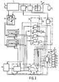
- Fig. 3 shows an embodiment of the device in Fig. 2, identical parts bearing the same reference numerals.
- the control means 8 comprise a first AND-gate 20 and a second AND-gate 21, each comprising an inverting input and non-inverting input.
- a signal which is high when the switch S1 is closed is applied to the non-inverting input of the gate 20 and to the inverting input of the gate 21 and a signal which is high when the power-supply circuit 1 is connected to the mains is applied to the inverting input of the gate 20 and to the non-inverting input of the gate 21. Consequently, the AND-gate 20 supplies a signal to the first adjusting means 10 in the battery-shaving mode and the AND-gate 21 supplies a signal to the second adjusting means 11 in the battery-charging mode.
- the adjusting means 10 comprise a read-only memory 23 which stores a value which determines the nominal discharging time of the battery 4 and a read-write memory 24, into which the value from the read-only memory 23 is written by a reset pulse each time that the device becomes operative and into which a value corrected by the correction means 15 is written when the device is in operation.
- the manner in which the reset pulse is generated is not described for the sake of simplicity.
- the adjusting means 11 are constructed in the same way as the adjusting means 10 and comprise a read-only memory 25 in which a value is stored which represent the nominal charging time of the battery 4 and a read-write memory 26 into which the value from the read-only memory 25 is written when there is a reset pulse and into which a corrected value is written when the device is in operation.
- the read-only memories 23 and 25 comprise, for example, an aluminium conductor pattern, whereas the read-write memories 24 and 26 comprise, for example shift registers.
- the computing means 12 comprise a memory in the form of a shift register 33, in the present example a 13-bit register in which the calculated charge status is stored.
- a shift register 33 in the present example a 13-bit register in which the calculated charge status is stored.
- the frequency divider 20 is a programmable frequency divider in which the frequency of the clock pulses supplied by the clock means 13 is divided by a number which is stored in the read-write memory 24 of the first adjusting means 10 in the battery-shaving mode and is divided by a number which is stored in the read-write memory 26 of the second adjusting means 20 in the battery-charging mode.
- Such frequency dividers are known per se and are not described in more detail.
- the clock means 13 comprise an oscillator for generating pulses and a number of fixed frequency dividers for deriving from these pulses the various clock frequencies required in the device. Similar clock means are well-known and therefore not described in more detail.
- the correction means 15 comprise a flip-flop 51 which is triggered by a detection signal from the detection means 7.
- the output of said flip-flop is connected to an input of a NOR-gate 57 whose other input is connected to the first bit of the register 33 and whose output is connected to one input of an AND-gate 53, whose other input is connected to the clock means 13 and whose output is connected both to the count-up (+) input of the read-write memory 24 and to an input of the OR-gate 32, the output of said flip-flop 51 being also connected to a first input of an AND-gate 54, whose second input is connected to the second bit of the register 33, whose third input is connected to the clock means 13 and whose output is connected both to the count-down (-) input of the read-write memory 24 and to an input of the OR-gate 31.
- the correction means 51 further comprise a flip-flop 52 which is triggered by a detection signal from the detection means 16. Its output is connected to a first input of an AND-gate 56 whose second input is connected to the 11th bit of the register 33, whose third input is connected to the clock means 13 and whose output is connected both to the count-up (+) input of the read-write memory 26 and to the input of the OR-gate 31, the output of the flip-flop 52 being also connected to a first input of an AND-gate 55, whose second input is connected to the clock means 13, whose third input is connected to the output of an inverter 58 whose input is connected to the 10th bit of the register 33 and whose output is connected to both the count-down (-) input of the read-write memory 26 and to an input of the OR-gate 32.
- the indicator means 14 comprises a liquid-crystal display means 40 with a bargraph with segment electrodes 41 to 45 and a back electrode 46. These electrodes 41 to 46 are driven by a driver circuit 47 in response to signals from the odd bits 1 to 9 of the shift register 33 of the computing means 12. The clock pulses for this driver circuit 47 are generated by the clock means 13.
- the segments 41 to 45 successively indicate the following charge statuses of the battery 4, again expressed in percentages of the battery capacity.
- the segment 41 starts to blink in the rhythm of a low-frequency clock signal applied to the driver circuit 47 by the clock means 13, if the driver circuit 47 receives a signal from the detection means 7 via the flip-flop 51 when the 10%-level is passed. It is also possible to represent the percentages separately or inscribed in the segments, for example in the sequence of 20, 40, 60, 80 and 100%.
- the indicator means further comprise a light-emitting diode (LED) 48 to indicate charging of the battery 4. This LED is driven by the signal on the inverting output of flip-flop 52. When the battery 4 is fully charged, the flip-flop 52 is triggered by the detection means 16, causing LED 48 to be turned off.
- LED light-emitting diode
- liquid-crystal display means 40 with extra electrodes in the form of letters and/or signs to indicate that the battery is nearly empty or nearly full or to indicate that the battery 4 is being charged or discharged.
- the operation of the device may be explained as follows. It is assumed that the battery 4 is fully charged, the bits 1 to 10 of the register 33 containing a logic "1" and the segments 41 to 45 of the display means 40 being visible.
- the power-supply circuit 1 is not connected to the mains the battery-shaving mode is obtained by closing the switch S1.
- the AND-gate 20 of the control means 8 then supplies signal which causes the value stored in the read-write memory 24 to be applied to the programmable frequency divider 30.
- a clock pulse appears on an output of the frequency divider 30 and is applied to the input 35 of the register 33 via the OR-gate 31. This causes the 10th bit of the charging register 33 to change to a logic "0".
- With the next clock pulse generated by the frequency divider 30 the 9th bit changes to a logic "0", the top segment 45 of the display means 40 being turned off via the driver circuit 47. In this way the contents of the shift register 33 is each time decremented by one bit.
- the charging register 33 is decremented too slowly.
- a number of bits in the register 33 still contain a logic "1". It is assumed that the bits 1, 2 and 3 contain a "1".
- the "1" in the 2nd bit and the output signal of flip-flop 51 open the AND-gate 54, which causes a clock pulse to be applied to the input 35 of the register 33 via the OR-gate 31, which sets the 3rd bit to "0".
- the same clock pulse is applied to the count-down input of the read-write memory 24, which causes the value stored therein to be decremented by 1.
- the next clock pulse is also applied to the input 35 of the register 33 via the AND-gate 54 and the OR-gate 31, which causes the 2nd bit to be set to "0", said pulse also being applied to the count-down input of the memory 24, so that the value stored is again decremented by 1.
- Only the 1st bit of the charging register 33 now contains a logic "1", which is in agreement with the detection by the means 7. This correction also results in a correction of the indication of the liquid-crystal display means 40, so that the segment 41 will blink to indicate that the battery 4 is nearly empty.
- the contents of the charging register 33 is decremented too fast.
- the 1st bit of register 33 is then set to "0" by a clock pulse from the frequency divider 30 before the passage of the 10%-level is detected by the detection means 7.
- the AND-gate 53 is opened via the NOR-gate 57, which causes a clock pulse to be applied to the input 34 of the register 33 via the OR-gate 32, which sets the 1st bit to "1".
- This clock pulse is then applied to the count-up (+) input of the read-write memory 24, which causes the value stored therein to be incremented by "1". This is repeated until the flip-flop 51 is triggered by the detection means 7. Since the value of the number stored in the memory 24 has been incremented, the calculated charge status during the next discharging period will be better in conformity with the actual charge status of the battery 4.
- the battery 4 is nearly empty.
- the power-supply circuit 1 is connected to the mains and the switch S1 is opened, the value stored in the read-write memory 26 is applied to the programmable frequency divider 30 via the AND-gate 21. After a number of clock pulses determined by this value the frequency divider 30 each time generates a clock pulse which is applied to the input 34 of the register 32 via the OR-gate 32, causing the contents of this register 33 to the incremented by one bit.
- the contents of the register 33 is incremented too slowly, so that at the instant at which the detection means 16 detects that the battery 4 is nearly fully charged the 10th bit of register 33 is still "0".
- This bit signal is inverted by the inverter 58 and applied to the AND-gate 55, which also receives the output signal of the flip-flop 52, so that a clock pulse appears on the output of the AND-gate 55.
- This pulse is applied to the input 34 of the register 33 via the OR-gate 32, so that the contents of this register is incremented by one bit and said pulse is also applied to the count-down (-) input of the read-write memory 26, so that the value stored in this memory is decremented by one. This is repeated until the 10th bit of the register 33 is "1" in accordance with the full-detection by the means 16.
- the contents of the register 33 is incremented too rapidly, so that at the instant at which the detection means 16 detects the fully charged condition one or more of the bits 11, 12 and 13 contain a logic "12".
- Triggering of the flip-flop 52 causes the AND-gate 56 to be opened, so that a clock pulse appears on its output. This pulse is applied to the input 35 of register 33 via the OR-gate 31, which causes the contents of this register to be decremented by one bit, said pulse being also applied to the count-up input of the read-write memory 26, which causes the value stored therein to be incremented. This is repeated until the 11th bit is "0".
- the correction of the value stored in the memory 26 ensures that the calculated charge status is better in conformity with the actual charge status of the battery 4 during the next charging process.
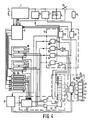
- Fig. 4 shows a second preferred embodiment based on the embodiment shown in Fig. 3, similar parts bearing the same reference numerals.
- a calculation of the charge status of the battery 4 is affected only in the battery-charging mode, in which the power-supply circuit 1 is connected to the mains and the switch S1 is closed and in the battery-shaving mode, in which the power-supply circuit 1 is not connected to the mains and the switch S1 is closed. In all the other possible modes no calculation and adaptation of the charge status is effected.
- the charge status of the battery is also calculated in these other modes.
- the power-supply circuit 1 is of the type that can charge the battery in the nearly empty condition with a relatively large charging current for a fixed time, so that the battery-shaving mode becomes available after a short lapse of time.
- Such a power-supply circuit is known from British Patent Application 2,125,641.
- the power-supply circuit 1 When the power-supply circuit 1 is connected to the mains and the switch S1 is closed, the power-supply circuit delivers a current to the load R L and also a relatively small current to the battery 4 if the battery voltage is lower than the value at which the voltage across the motor R L is stabilised. As a rule, this voltage is some tenths of volts lower than the battery voltage detected by the detection means 16 in the fully charged condition. When peak loads are ignored, the current supplied by the power-supply circuit 1 is generally larger than the current necessary to maintain the voltage across the motor R L at the stabilised value. The battery 4 is charged by the difference between these currents. This condition is referred to as the mains-shaving mode.
- the device comprises third adjusting means 60 comprising a read-only memory 61 in which a value is stored which represents the charging time of the battery 4 in the mains-shaving mode.
- the value stored in the memory 61 is applied to the programmable frequency divider 30. After a number of clock pulses of the clock means 13 determined by this value this frequency divider 30 each time generates a clock pulse, which is applied to the input 34 of register 33 via the OR-gate 32, causing the contents of the register to be incremented by one bit.
- the power-supply circuit 1 is rendered inoperative until the battery voltage has decreased below the stabilised motor voltage.
- power-supply circuits of the type currently used change over to a trickle-charging mode, in which the battery 4 is charged with a relatively small trickle of charging current to keep the battery in the fully charged condition.
- the device is provided with fourth adjusting means 62, comprising a read-only memory 63, in which a value is stored which represents the charging time of the battery 4 required for fully charging the battery with the trickle-charging current.
- the power-supply circuit 1 When the trickle-charging mode is detected by the control means 8 from the signals indicating the battery-charging mode and the output signal of the flip-flop 52, the power-supply circuit 1 is changed over to trickle charging by the control means 8 and the value stored in the memory 63 is applied to the frequency divider 30. After a number of clock pulses from the clock means 13 determined by this value this causes the frequency divider 30 to supply a clock pulse to the input 34 of the register 33 via the OR-gate 32, so that the contents of this register is each time incremented by one bit.
- the device comprises fifth adjusting means 64 comprising a read-only memory 65, in which a value is stored, which represents the discharging time of the battery 4 in the case that it would be fully discharged by self-discharging.
- the control means 8 On detection of the self-discharging condition by the control means 8 the value stored in the memory 65 is applied to the programmable frequency divider 30. After a relatively large number of clock pulses from the clock means 13 this causes the frequency divider 30 to apply a clock pulse to the input 35 of register 33 via the OR-gate 31, so that the contents of this register is each time to be decremented by one bit.
- the power supply circuit 1 can supply a relatively large charging current. If the power-supply circuit 1 is connected to the mains, the switch S1 is closed and the flip-flop 51 has been triggered by the detection device 7 due to the battery 4 being nearly empty, the power-supply circuit 1 is changed over to the quick-charging mode by the control means 8. The power-supply circuit 1 then supplies a relatively large charging current for a relatively short time. During this time the battery 4 is charged to such an extent that energy is available for at least one shave.
- the device comprises sixth adjusting means 66 comprising a read-only memory 67 ub which a value is stored which represents the charging time of the battery 4 in the case that it would be fully charged by the quick-charging current.
- the value stored in memory 66 is applied to the frequency divider 30. After a relatively small number of clock pulses determined by this value this each time causes the frequency divider 30 to supply a clock pulse to the input 34 of register 33 via the OR-gate 32, so that the contents of this register is each time incremented by one bit.
- the battery voltage will decrease below the minimum supply voltage required for the electronic circuits when the battery 4 is discharged further after a passage of the 10%-level has been detected by the detection means, so that said circuits become inoperative.
- the device When the battery 4 is subsequently charged with the increased charging current, the device will become operative again above a certain battery voltage.
- the segment 41 of the indicator means 40 then blinks until the battery voltage has increased above the 10%-level.
- the read-only memory 64 may be dispensed with. It is also possible to combine the read-only memories 60 and 62 to form one memory if the charging current in the trickle-charging mode is of the same order of magnitude as in the mains-shaving mode.
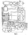
- Fig. 5 shows a device for indicating the charge status of a battery in accordance with a third embodiment, identical parts bearing the same reference numerals as in Fig. 4.
- the adjusting means 10 again comprise a read-only memory 23 in which a value representing the nominal discharging time of the battery is stored and a read-write memory 24 into which the value from the read-only memory 23 is entered each time that the device becomes operative and which during operation of the device stores a value corrected by the correction means 15.
- the adjusting means 11 are of the same construction as the adjusting means 10, the read-only memory 25 storing a value representing the nominal charging time of the battery 4 and the read-write memory 26 being loaded with the value from the read-only memory 25 when the device becomes operative and with a value corrected by the correction means 15 when the device is in operation.
- the computing means 12 again comprise a programmable frequency divider 30 and a register 33 which stores the computed charge status.
- the register 33 is, for example, a 36-bit register.
- the indicator means 14 is of the same construction as that in the embodiment shown in Fig. 4, except that now the driver circuit 47 drives a succeeding segment electrode of the liquid-crystal display means 40 after every 8 clock pulses applied to the register 33 starting from the empty situation.
- the segments 41 to 45 respectively correspond to 20, 40, 60, 80 and 100% of the battery capacity.
- the following Table gives the relationship between the contents of the register and the number of segment electrodes being driven.
- the segment 41 moreover starts to blink in the rhythm of a low-frequency signal supplied to the driver circuit by the clock means 13 if upon passage of the 10%-level the detection means 7 supply a signal to the driver circuit via the flip-flop 51.
- the segments 45 of the display means 40 is turned off after five clock pulses from the divider 30 and subsequently a following segment is turned off after every eight clock pulses from the frequency divider 30.
- the clock pulses applied to the frequency divider 30 are also fed to a fixed frequency divider 84 via an AND-gate 83, which divider 84 divides the frequency of the incoming pulses by a value equal to the number of bit positions of the register 33, i.e. 36 in the present example.
- the output pulses of the frequency divider 84 are applied to a register 82. At the instant at which the detection means detects a passage of the 10%-level a signal from the flip-flop 51 causes the contents of the register 82 to be transferred to the read-write memory 24.
- the value stored in the read-write memory 26 is transferred to the programmable frequency divider 30.
- Clock pulses from the clock means 13, which for practical reasons are divided by means of a fixed frequency divider 70 are, applied to the input of the divider 30 via an AND-gate 71.
- the frequency divider 30 supplies a clock pulse to the count-up input 34 of the register 34, so that the first bit changes to a logic "1".
- the bottom segment 41 charges over from the blinking mode to the continuously turned-on mode.
- the segments 42 to 45 are driven each time that 8 clock pulses have been applied to the register 33.
- the clock pulses applied to the frequency divider 30 are also applied to a fixed frequency divider 81 via an AND-gate 80, which divider 81 divides the frequency of the incoming pulses by a fixed value which in the present example is equal to 31.
- the output pulses of the frequency divider 81 are applied to the register 82.
- the detection means 16 detects the fully-charged level the contents of the register 82 is loaded into the read-write memory 26 in response to a signal from the flip-flop 52. If it is assumed that the charging time of the battery 4 is, for example, shorter than the discharging time represented by the value in the memory 26, the contents of the register 33 is incremented too slowly.
- the adjusting means which establish the charging or discharging time of the battery 4 in the other charging and discharging modes which are possible comprise a memory common to the first adjusting means 11 or the second adjusting means 12.
- the adjusting means for the self-discharging mode comprise the first adjusting means 10 and a fixed frequency divider 78 connected in series with the programmable frequency divider 30.
- the value from the read-write memory 24 is applied to the frequency divider 30 under control of the control means 8.
- clock pulses from the clock means 13 are applied to the frequency divider 78 and subsequently to the frequency divider 30, so that after a number of clock pulses determined by the value from the memory 24 the contents of the charge register 33 is adapted and the value stored in the memory 24 is not corrected.
- the charging time of the battery 4 defined by the adjusting means for the self-discharging mode is modified by a correction of the value stored in the memory 24 for the battery-shaving mode.
- the adjusting means for the quick-charging mode comprise the second adjusting means 11 and a fixed frequency divider 74 connected in series with the programmable frequency divider 30.
- the value from the memory 26 is transferred to the programmable frequency divider 30.
- Clock pulses from the clock means 13 are applied to the frequency divider 74 via the AND-gate 73 and subsequently to the frequency divider 30, so that the contents of the register 33 is incremented each time after a number of clock pulses determined by the value from the memory 26.
- the adjusting means for the mains-shaving mode and trickle-charging mode comprise the second adjusting means 11 and the fixed frequency dividers 76 and 79 respectively.
- clock pulses are applied to the frequency divider 76 via the AND-gate 75 and in the trickle-charging mode these pulses are applied to the frequency divider 79 via the AND-gate 87, so that the contents of the register 33 is also adapted in these modes.
- circuits 8, 10, 11, 12, 14 and 15 may be realized by means of a microprocessor.
- Fig. 6 shows a fourth embodiment of the invention in which the functions of the control means, the adjusting means, the computing means and the correction means are performed by a microprocessor.
- the microprocessor is for example of the type Toshiba M 50.760-XXXP. This microprocessor requires a minimum supply voltage of 2 V, which is delivered by the battery 4. For the sake of simplicity the external components necessary for a correct operation of the microprocessor are not shown.
- the display means 40 again comprises 5 segment electrodes 41 to 45.
- the segment electrode 41 displays fixed information in the form of the letters RECH, which denotes the fully discharged state of the battery 4 and, consequently, the need to recharge the battery 4.
- RECH the fully discharged state of the battery 4
- the segment electrode 45 a number of electrodes forming the words FULL are arranged, which when driven indicate that the battery is charged to substantially the full extent.
- the full battery capacity is divided in accordance with the scales -10, 0, 20, 40, 60, 80 and 100%.
- the segment electrodes 41 to 45 in this order, denote the ranges 0-20; 20-40; 40-60; 60-80 and 80-100%.
- the 0%-level corresponds to the condition in which the detection means 7 detect the level of 10% of the full battery capacity.
- the segment electrode 41 will blink.
- this segment electrode 41 keeps blinking until the voltage level is reached below which the display means 40 no longer functions.
- This voltage level corresponds to the -10%-level.
- the fixed information RECH is displayed as a sign that the battery 4 must be recharged.
- the detection means 16 detects a voltage level which on the display-means scale corresponds to the 80%-level. When this level is reached the charging current of the circuit 1 is set to the slow-charging level to charge the battery 4 completely within a predetermined time. When this level is detected all the segment electrodes and the FULL indication are driven. However, for computing, the charge status the micro-processor 9 proceeds with the 80%-level. If the computed charge status is already higher prior to detection of the 80%-level, the display means continues to display the 80%-level until this level is detected.
- a first read-only memory in the microprocessor 90 stores a value representing 1/10 of the nominal discharging time. When the device becomes operative in the battery-shaving mode this value is loaded into a counter formed by a part of the memory. This counter then counts down with clock pulses of a fixed frequency derived from the internal clock of the microprocessor.
- the processor also comprises a charge register storing a number which may have values from 0 to 9. This value represents the computed charge status, which is displayed by the display means 40. When it is assumed that the battery 4 is fully charged, i.e. the charge register contains the number 9, the charge register is set to 8 after the counter has counted down to zero.
- the value from the first read-only memory is each time again applied to the counter, after which it counts down again until it is empty. If the detection means 7 detects the 10%-level and the state of the charge register is unequal to zero at this instant, the processor computes a new value from the old values and the state of the charge register, which new values represents 1/10 of the discharging time. This new value is written into a first read-write register and is transferred to the counter during the next discharging process.
- a second read-only memory in the microprocessor stores a value which represents 1/10 of the nominal charging time. In the battery-charging mode this value is applied to the counter when the device becomes operative, which counter again counts down until it is empty with clock pulses of a fixed frequency derived from the internal clock. When it is assumed that the battery 4 is almost empty, i.e. position 0 of the charge register, the charge register is now set to position 1. In this way the value stored in the second read-only memory is each time transferred to the counter in the battery-charging mode, which counter each time counts down until it is empty, resulting in the contents of the charge register being incremented by one each time.
- the processor derives a new value representing 1/10 of the charging time from the old value and the state of the charge register. This new value is entered into a read-write memory. The next time that the battery 4 is charged, this value is each time applied to the counter. Adaptation of the computed charge status in the quick-charging, trickle-charging, mains-shaving and self-discharging modes can be realized simply in the present embodiment by vacating the counters with clock pulses of a different frequency.
- the invention is not limited to the embodiments described herein, many modifications being conceivable to those skilled in the art within the scope of the invention.
- the computed charge status during discharging and/or charging of the battery is compared with one actual charge status, after which the computed charge status is corrected.
Landscapes
- Engineering & Computer Science (AREA)
- Power Engineering (AREA)
- Physics & Mathematics (AREA)
- General Physics & Mathematics (AREA)
- Charge And Discharge Circuits For Batteries Or The Like (AREA)
- Tests Of Electric Status Of Batteries (AREA)
- Secondary Cells (AREA)
- Magnetic Treatment Devices (AREA)
- Adornments (AREA)
Claims (18)
- Dispositif pour indiquer l'état de charge d'une batterie (4) pendant la charge et/ou la décharge, comprenant:
un circuit d'alimentation électrique (1) pour charger la batterie (4) et/ou exciter un dispositif consommateur (RL);
une horloge pour produire des impulsions d'horloge pendant la charge et/ou la décharge de la batterie (4);
des moyens de calcul (9) pour calculer l'état de charge sur base des impulsions d'horloge produites, et
un moyen indicateur (14) pour indiquer l'état de charge calculé; caractérisé en ce que:
les moyens de calcul (9) comprennent:
un premier moyen de réglage (10) pour régler un temps de décharge de la batterie (4) sur une première valeur pendant la décharge de la batterie (4) par le dispositif consommateur (RL) et/ou un deuxième moyen de réglage (11) pour régler un temps de charge de la batterie (4) sur une deuxième valeur pendant la charge de la batterie (4) par le circuit d'alimentation électrique (1) en l'absence de dispositif consommateur, et des moyens de mesure du temps (12) pour déterminer, uniquement sur base des impulsions d'horloge produites, le rapport entre le temps de décharge écoulé et le temps de décharge réglé et/ou pour déterminer le rapport entre le temps de charge écoulé et le temps de charge réglé, ces rapports représentant l'état de charge calculé;
et en ce que le dispositif comprend, en outre:
des moyens de détection (7, 16) pour détecter au moins un état de charge réel de la batterie (4) pendant virtuellement chaque cycle de décharge et/ou virtuellement chaque cycle de charge de la batterie (4); des moyens de correction (15) pour corriger l'état de charge calculé et pour corriger la première valeur du premier moyen de réglage (10) et/ou la deuxième valeur du deuxième moyen de réglage (11) lorsqu'une différence apparaît entre ledit au moins un état de charge réel détecté par les moyens de détection (7) et l'état de charge calculé à l'instant de la détection, et un moyen de commande (8) pour commander le premier et/ou le deuxième moyen de réglage (10, 11) et les moyens de mesure du temps (12). - Dispositif suivant la revendication 1, caractérisé en ce que les moyens de détection (7, 16) destinés à détecter ledit au moins un état de charge réel pendant la décharge de la batterie (4) comprennent un premier dispositif détecteur pour la détection d'une diminution de la tension de la battérie en dessous d'une tension de référence.
- Dispositif suivant la revendication 1, caractérisé en ce que les moyens de détection (7, 16) destinés à détecter ledit au moins un état de charge pendant la charge de la batterie (4) comprennent un deuxième dispositif détecteur pour la détection de l'état en substance complètement chargé de la batterie (4).
- Dispositif suivant la revendication 3, caractérisé en ce que le deuxième dispositif détecteur comprend un dispositif pour la détection d'une diminution de la tension de la battérie qui se produit lorsque la batterie (4) se trouve dans l'état en substance complètement chargé.
- Dispositif suivant la revendication 3, caractérisé en ce que le deuxième dispositif détecteur comprend un dispositif pour détecter si la tension de la batterie est égale à une tension de référence.
- Dispositif suivant l'une quelconque des revendications précédentes, caractérisé en ce que les moyens de calcul (9) comprennent, en outre, un troisième moyen de réglage (60) pour régler un temps de charge de la batterie (4) sur une troisième valeur pendant la charge de la batterie (4) par le circuit d'alimentation électrique (1) dans son état avec le dispositif consommateur actif.
- Dispositif suivant l'une quelconque des revendications précédentes, caractérisé en ce que les moyens de calcul (9) comprennent, en outre, un quatrième moyen de réglage (62) pour régler un temps de charge de la batterie (4) sur une quatrième valeur pendant la charge de la batterie (4) par le circuit d'alimentation électrique (1) dans l'état sans dispositif consommateur ainsi que lorsque la batterie (4) se trouve dans l'état en substance complètement chargé.
- Dispositif suivant l'une quelconque des revendications précédentes, caractérisé en ce que les moyens de calcul (9) comprennent, en outre, un cinquième moyen de réglage (64) pour régler un temps de décharge de la batterie (4) sur une cinquième valeur pendant la décharge de la batterie (4) lorsque le circuit d'alimentation électrique (1) et le dispositif consommateur (RL) sont inactifs.
- Dispositif suivant l'une quelconque des revendications précédentes, caractérisé en ce que le circuit d'alimentation électrique (1) est à même de fournir à la batterie (4), pendant une fraction de temps de charge, un courant de charge qui est plus intense que le courant de charge fourni pendant le reste du temps de charge de la batterie (4), et en ce que les moyens de calcul (9) comprennent, en outre, un sixième moyen de réglage (66) pour régler un temps de charge de la batterie (4) sur une sixième valeur pendant la charge de cette batterie (4) au moyen d'un courant de charge accru lorsque le dispositif consommateur (RL) est inactif et que la batterie (4) est en substance vide.
- Dispositif suviant l'une quelconque des revendications précédentes, caractérisé:
en ce que chacun des moyens de réglage (10, 11, 60, 62, 64, 66) comprend un dispositif à mémoire (24, 26, 61, 63, 65, 67) pour stocker la valeur réglée du moyen de réglage en question;
en ce que les moyens de mesure du temps (12) comprennent:
un diviseur de fréquence réglable (36) pour diviser la fréquence des impulsions d'horloge de l'horloge (13) en fonction de la valeur stockée dans le moyen de réglage en question, et
un dispositif à mémoire (33) comportant un nombre fixe d'emplacements pour le stockage du nombre d'impulsions d'horloge fournies par le diviseur de fréquence (30), ce nombre représentant l'état de charge calculé. - Dispositif suivant la revendication 10 découlant de l'une quelconque des revendications 6 à 9, caractérisé:
en ce que le premier moyen de réglage (10) comprend une première mémoire (24) pour le stockage d'une première valeur, qui représente le temps de décharge de la batterie (4) lorsqu'elle est déchargée par le dispositif consommateur (RL);
en ce que le deuxième moyen de réglage (11) comprend une deuxième mémoire (26) pour le stockage de la deuxième valeur, qui représente le temps de charge de la batterie (4) par le circuit d'alimentation électrique (1), et
en ce que chacun des autres moyens de réglage comprend une mémoire (24, 26) commune au premier ou au deuxième moyen de réglage (10, 11) et des moyens (73, 75, 77, 87) pour connecter un diviseur de fréquence fixe (74, 76, 78) en série avec le diviseur de fréquence programmable (30). - Dispositif suivant l'une quelconque des revendications 1 à 9, caractérisé:
en ce que chacun des moyens de réglage (10, 11, 62, 64, 66) comprend une mémoire (24, 26, 61, 63, 65, 67) destinée à stocker la valeur réglée du moyen de réglage en question;
en ce que les moyens de mesure du temps (12) comprennent:
une mémoire dont le nombre d'emplacements de stockage est proportionnel à la valeur stockée dans le moyen de réglage en question, et
un diviseur de fréquence pour diviser la fréquence des impulsions d'horloge par un nombre fixe. - Dispositif suivant la revendication 12, découlant de l'une quelconque des revendications 6 à 8, caractérisé:
en ce que le premier moyen de réglage (10) comprend une mémoire pour le stockage de la première valeur;
en ce que le deuxième moyen de réglage (11) comprend une mémoire pour le stockage de la deuxième valeur, et
en ce que chacun des autres moyens de réglage (60, 62, 64, 66) comprend une mémoire commune au premier ou au deuxième moyen de réglage pour connecter un deuxième diviseur de fréquence fixe en série avec ledit diviseur de fréquence fixe. - Dispositif suivant l'une quelconque des revendications précédentes, caractérisé en ce que le moyen indicateur (14) comprend un dispositif d'affichage électrooptique passif.
- Dispositif suivant la revendication 14, caractérisé en ce que le moyen indicateur (14) comprend un dispositif d'affichage à cristaux liquides.
- Dispositif suivant l'une quelconque des revendications précédentes, caractérisé en ce que le moyen indicateur (14) comprend un dispositif indicateur électroacoustique.
- Dispositif suivant l'une quelconque des revendications précédentes, caractérisé en ce que le moyen indicateur (14) comprend un dispositif pour indiquer l'état de charge de la batterie après que le dispositif a été éteint.
- Appareil de rasage à sec, caractérisé en ce qu'il comprend un dispositif suivant l'une quelconque des revendications précédentes.
Priority Applications (1)
| Application Number | Priority Date | Filing Date | Title |
|---|---|---|---|
| AT87200844T ATE55494T1 (de) | 1986-05-15 | 1987-05-11 | Vorrichtung zum anzeigen des ladezustandes einer batterie. |
Applications Claiming Priority (2)
| Application Number | Priority Date | Filing Date | Title |
|---|---|---|---|
| NL8601243 | 1986-05-15 | ||
| NL8601243A NL8601243A (nl) | 1986-05-15 | 1986-05-15 | Inrichting voor het weergeven van de ladingstoestand van een batterij. |
Publications (3)
| Publication Number | Publication Date |
|---|---|
| EP0248461A1 EP0248461A1 (fr) | 1987-12-09 |
| EP0248461B1 EP0248461B1 (fr) | 1990-08-08 |
| EP0248461B2 true EP0248461B2 (fr) | 1994-05-11 |
Family
ID=19848022
Family Applications (1)
| Application Number | Title | Priority Date | Filing Date |
|---|---|---|---|
| EP87200844A Expired - Lifetime EP0248461B2 (fr) | 1986-05-15 | 1987-05-11 | Dispositif pour indiquer l'état de charge d'une batterie |
Country Status (14)
| Country | Link |
|---|---|
| US (1) | US4775827A (fr) |
| EP (1) | EP0248461B2 (fr) |
| JP (1) | JPH069432B2 (fr) |
| KR (2) | KR950013237B1 (fr) |
| CN (1) | CN1012759B (fr) |
| AR (1) | AR246378A1 (fr) |
| AT (1) | ATE55494T1 (fr) |
| BR (1) | BR8702400A (fr) |
| CA (1) | CA1262934A (fr) |
| DE (2) | DE3764189D1 (fr) |
| ES (1) | ES2018004T5 (fr) |
| HK (1) | HK15593A (fr) |
| NL (1) | NL8601243A (fr) |
| SG (1) | SG113292G (fr) |
Cited By (1)
| Publication number | Priority date | Publication date | Assignee | Title |
|---|---|---|---|---|
| US7496460B2 (en) | 2006-09-06 | 2009-02-24 | Eastway Fair Company Limited | Energy source monitoring and control system for power tools |
Families Citing this family (67)
| Publication number | Priority date | Publication date | Assignee | Title |
|---|---|---|---|---|
| GB2196450B (en) * | 1986-10-20 | 1991-02-13 | Mars Inc | Data-storing tokens |
| US4902960A (en) * | 1988-03-17 | 1990-02-20 | Myron Zucker, Inc. | Voltage input for harmonimeter, and methods of constructing and utilizing same |
| JPH0799384B2 (ja) * | 1988-09-13 | 1995-10-25 | 日本電気株式会社 | 電池残量表示装置 |
| JPH07120536B2 (ja) * | 1989-03-31 | 1995-12-20 | 三菱電機株式会社 | 電池残量認識装置 |
| DE3920629C2 (de) * | 1989-06-23 | 1994-05-11 | Woehrle Martin | Verfahren zur Bestimmung der Kapazität eines elektrischen Ni-Cd-Akkumulators und zur Ladung desselben |
| US5187424A (en) * | 1989-10-14 | 1993-02-16 | Mercedes-Benz Ag | Process for determining the state of a battery |
| CN1027192C (zh) * | 1989-10-25 | 1994-12-28 | 菲利浦光灯制造公司 | 电池充电装置 |
| DE69025868T2 (de) * | 1989-12-11 | 1996-09-05 | Canon Kk | Ladegerät |
| SE466008B (sv) * | 1990-03-29 | 1991-12-02 | Volvo Ab | Anordning vid bestaemning av laddningsstatus foer ett startbatteri hos ett motorfordon |
| JPH03282916A (ja) * | 1990-03-30 | 1991-12-13 | Toshiba Corp | 電源制御装置および方法 |
| US5280231A (en) * | 1990-07-02 | 1994-01-18 | Nippondenso Co., Ltd. | Battery condition detecting apparatus and charge control apparatus for automobile |
| JPH04109832A (ja) * | 1990-08-28 | 1992-04-10 | Sony Corp | 2次電池用充電器 |
| US5432429A (en) * | 1990-10-23 | 1995-07-11 | Benchmarq Microelectronics, Inc. | System for charging/monitoring batteries for a microprocessor based system |
| US6377028B1 (en) | 1990-10-23 | 2002-04-23 | Texas Instruments Incorporated | System for charging monitoring batteries for a microprocessor based method |
| US5187425A (en) * | 1990-11-09 | 1993-02-16 | Ast Research, Inc. | Rechargeable battery controller |
| US5345392A (en) * | 1991-01-25 | 1994-09-06 | International Business Machines Corporation | Battery charge monitor for a personal computer |
| DK25391D0 (da) * | 1991-02-14 | 1991-02-14 | Pan Europ Holding S A | Fremgangsmaade og apparat til opladning af et genopladeligt batteri |
| GB9107481D0 (en) * | 1991-04-09 | 1991-05-22 | Yang Tai Her | A close-loop controlled charging device with reference battery saturation status |
| US5325041A (en) * | 1991-08-09 | 1994-06-28 | Briggs James B | Automatic rechargeable battery monitoring system |
| US5315228A (en) * | 1992-01-24 | 1994-05-24 | Compaq Computer Corp. | Battery charge monitor and fuel gauge |
| US5357203A (en) * | 1992-07-08 | 1994-10-18 | Benchmarq Microelectronics, Inc. | Battery monitoring circuit for operating with high battery discharge rates |
| US5284719A (en) * | 1992-07-08 | 1994-02-08 | Benchmarq Microelectronics, Inc. | Method and apparatus for monitoring battery capacity |
| US5440221A (en) * | 1992-07-08 | 1995-08-08 | Benchmarg Microelectronics, Inc. | Method and apparatus for monitoring batttery capacity with charge control |
| US5592069A (en) | 1992-10-07 | 1997-01-07 | Dallas Semiconductor Corporation | Battery charger |
| US5539298A (en) * | 1993-03-19 | 1996-07-23 | Compaq Computer Corporation | Pulse charge technique to trickle charge a rechargeable battery |
| US5514946A (en) * | 1993-03-19 | 1996-05-07 | Compaq Computer Corp. | Battery pack including static memory and a timer for charge management |
| US5638540A (en) * | 1993-06-08 | 1997-06-10 | U.S. Robotics Mobile Communication Corp. | Portable computer/radio power management system |
| USRE39908E1 (en) | 1993-12-27 | 2007-11-06 | Hitachi, Ltd. | Secondary battery power storage system |
| JP2979939B2 (ja) | 1993-12-27 | 1999-11-22 | 株式会社日立製作所 | 二次電池システムの運転方法 |
| JPH07222370A (ja) * | 1994-01-28 | 1995-08-18 | Sanyo Electric Co Ltd | 温度センサーを有する充電器 |
| DE4409736A1 (de) * | 1994-03-22 | 1995-09-28 | Braun Ag | Verfahren und Vorrichtung zur Pflege von in einem Gerät fest eingebauten Akkus |
| US5600229A (en) * | 1994-03-31 | 1997-02-04 | Samsung Heavy Industries Co., Ltd. | System for monitoring energy performance of secondary battery, and method therefor |
| JPH07284233A (ja) * | 1994-04-05 | 1995-10-27 | Sony Corp | 充電方法及び充電装置 |
| JP3379283B2 (ja) * | 1994-07-04 | 2003-02-24 | 株式会社日本自動車部品総合研究所 | バッテリ充電状態検出方法 |
| DE4437647A1 (de) * | 1994-10-21 | 1996-05-02 | Braun Ag | Verfahren zur Bestimmung des Ladezustandes eines Akkumulators |
| US5831350A (en) * | 1995-12-15 | 1998-11-03 | Compaq Computer Corporation | System using interchangeable nickel-based and lithium ion battery packs |
| US5903137A (en) * | 1995-12-15 | 1999-05-11 | Compaq Computer Corporation | Battery pack with single charge inhibit/regulator transistor |
| US5764028A (en) * | 1995-12-15 | 1998-06-09 | Compaq Computer Corporation | Battery pack with single charge-inhibit/regulator transistor |
| US5641587A (en) * | 1995-12-15 | 1997-06-24 | Compaq Computer Corporation | Battery pack with a monitoring circuit for a known system |
| US5721482A (en) * | 1996-01-16 | 1998-02-24 | Hewlett-Packard Company | Intelligent battery and method for providing an advance low battery warning for a battery powered device such as a defibrillator |
| US5677077A (en) * | 1996-02-22 | 1997-10-14 | Compaq Computer Corporation | Sensor circuit for providing maximum and minimum cell voltages of a battery |
| JP3836152B2 (ja) * | 1996-06-21 | 2006-10-18 | コーニンクレッカ フィリップス エレクトロニクス エヌ ヴィ | 充電可能バッテリを有する装置用電源システムと、このような電源システム用電源ユニットおよび装置 |
| WO1998040925A1 (fr) * | 1997-03-12 | 1998-09-17 | Us Nanocorp. | Procede pour determiner l'etat de charge au moyen d'un systeme intelligent |
| US6456988B1 (en) * | 1997-03-12 | 2002-09-24 | U.S. Nanocorp Inc. | Method for determining state-of-health using an intelligent system |
| US6018227A (en) * | 1998-06-22 | 2000-01-25 | Stryker Corporation | Battery charger especially useful with sterilizable, rechargeable battery packs |
| GB2346745A (en) * | 1999-02-11 | 2000-08-16 | Nec Technologies | Battery charger start up timer for fully charged battery |
| US6445936B1 (en) * | 1999-11-16 | 2002-09-03 | Agere Systems Guardian Corp. | Low power consumption quick charge for wireless device |
| JP4157317B2 (ja) * | 2002-04-10 | 2008-10-01 | 株式会社日立製作所 | 状態検知装置及びこれを用いた各種装置 |
| TWI230797B (en) * | 2002-11-08 | 2005-04-11 | Mteq Systems Inc | Method for counting cycle count of a smart battery and method and device for correcting full charge capacity of a smart battery using the same |
| DE10253051B4 (de) * | 2002-11-14 | 2005-12-22 | Vb Autobatterie Gmbh | Verfahren zur Ermittlung der Ladungsaufnahme einer Speicherbatterie |
| US7348763B1 (en) | 2002-12-20 | 2008-03-25 | Linvatec Corporation | Method for utilizing temperature to determine a battery state |
| JP2004312849A (ja) * | 2003-04-04 | 2004-11-04 | Sanyo Denki Co Ltd | 蓄電池劣化判定回路付無停電給電装置 |
| US7405537B2 (en) * | 2004-12-20 | 2008-07-29 | Gm Global Technology Operations, Inc. | Apparatus and methods for estimating the state-of-charge of a power source |
| JP3838258B2 (ja) * | 2005-03-10 | 2006-10-25 | ソニー株式会社 | バッテリー残量表示方法 |
| JP2008023025A (ja) * | 2006-07-20 | 2008-02-07 | Matsushita Electric Works Ltd | シェーバ洗浄装置およびシェーバシステム |
| DE102008049832A1 (de) * | 2008-10-01 | 2010-04-15 | Novoferm Tormatic Gmbh | Steuerung für ein Tor oder dergleichen sowie Verfahren zum Betrieb einer derartigen Steuerung |
| US7969177B2 (en) * | 2008-12-22 | 2011-06-28 | LTX—Credence Corporation | System and method for thermal limit control |
| JP4983818B2 (ja) * | 2009-02-12 | 2012-07-25 | ソニー株式会社 | 電池パックおよび電池容量計算方法 |
| CN102298910A (zh) * | 2010-06-28 | 2011-12-28 | 北京思旺电子技术有限公司 | 能够显示电量的lcd屏驱动电路及电池充电器 |
| JP4977797B1 (ja) * | 2011-11-30 | 2012-07-18 | 和征 榊原 | 電池システム |
| CN202585667U (zh) * | 2012-05-17 | 2012-12-05 | 天津市畅和科技有限公司 | 一种用于智能蓄电池的激活装置 |
| KR101428293B1 (ko) * | 2012-12-18 | 2014-08-07 | 현대자동차주식회사 | 전기자동차용 보조배터리의 주기적 충전 방법 |
| CN104076897B (zh) * | 2013-03-28 | 2017-08-29 | 联想(北京)有限公司 | 一种信息处理方法及电子设备 |
| JP6095502B2 (ja) * | 2013-06-25 | 2017-03-15 | 株式会社マキタ | バッテリパック |
| CN103872733B (zh) * | 2014-03-18 | 2016-05-25 | 何岳明 | 一种锂电池组的充电状态指示电路 |
| JP6617189B1 (ja) | 2018-10-31 | 2019-12-11 | 日本たばこ産業株式会社 | エアロゾル吸引器用の電源ユニット、エアロゾル吸引器、エアロゾル吸引器の電源制御方法、及びエアロゾル吸引器の電源制御プログラム |
| CN218984883U (zh) | 2019-07-01 | 2023-05-09 | 思派创品牌公司 | 电动梳理器具 |
Family Cites Families (10)
| Publication number | Priority date | Publication date | Assignee | Title |
|---|---|---|---|---|
| DE2313566A1 (de) * | 1973-03-19 | 1974-10-03 | Zeh Kg Wilhelm | Verfahren fuer die unmittelbare messung und anzeige der jeweiligen ladung einer akkumulatorenbatterie und vorrichtung hierzu |
| DE2851599C2 (de) * | 1978-11-29 | 1987-01-29 | Theo Benning Elektrotechnik Und Elektronik Gmbh & Co Kg, 4290 Bocholt | Vorrichtung zur selbsttätigen Prüfung der Kapazität von Batterien |
| CH648936A5 (en) * | 1980-12-31 | 1985-04-15 | Helmut Koechler | Method for monitoring the discharge characteristic of a galvanic element and device for carrying out the method |
| DE3100503A1 (de) * | 1981-01-09 | 1982-08-05 | Siemens AG, 1000 Berlin und 8000 München | Anordnung zur kontrolle des ladezustands einer batterie |
| US4387334A (en) * | 1981-06-05 | 1983-06-07 | Rockwell International Corporation | Battery monitor circuit |
| US4553081A (en) * | 1982-06-07 | 1985-11-12 | Norand Corporation | Portable battery powered system |
| NL8204628A (nl) * | 1982-11-30 | 1984-06-18 | Philips Nv | Inrichting voor het signaleren van een bepaalde laadtoestand van een accubatterij. |
| JPS59155840U (ja) * | 1983-04-05 | 1984-10-19 | 九州日立マクセル株式会社 | 充電量表示回路 |
| JPS60255025A (ja) * | 1984-05-28 | 1985-12-16 | 株式会社三陽電機製作所 | 充電制御装置 |
| US4638237A (en) * | 1985-01-03 | 1987-01-20 | Pulse Electronics, Inc. | Battery condition indicator |
-
1986
- 1986-05-15 NL NL8601243A patent/NL8601243A/nl not_active Application Discontinuation
-
1987
- 1987-01-21 KR KR87000465A patent/KR950013237B1/ko not_active Expired - Fee Related
- 1987-05-05 US US07/046,977 patent/US4775827A/en not_active Expired - Lifetime
- 1987-05-11 DE DE8787200844T patent/DE3764189D1/de not_active Expired - Lifetime
- 1987-05-11 DE DE198787200844T patent/DE248461T1/de active Pending
- 1987-05-11 ES ES87200844T patent/ES2018004T5/es not_active Expired - Lifetime
- 1987-05-11 EP EP87200844A patent/EP0248461B2/fr not_active Expired - Lifetime
- 1987-05-11 AT AT87200844T patent/ATE55494T1/de active
- 1987-05-12 KR KR870004635A patent/KR870011715A/ko not_active Withdrawn
- 1987-05-12 CN CN87103529A patent/CN1012759B/zh not_active Expired
- 1987-05-12 AR AR87307537A patent/AR246378A1/es active
- 1987-05-12 CA CA000536887A patent/CA1262934A/fr not_active Expired
- 1987-05-12 BR BR8702400A patent/BR8702400A/pt not_active IP Right Cessation
- 1987-05-13 JP JP62114892A patent/JPH069432B2/ja not_active Expired - Lifetime
-
1992
- 1992-11-02 SG SG1132/92A patent/SG113292G/en unknown
-
1993
- 1993-02-25 HK HK155/93A patent/HK15593A/en not_active IP Right Cessation
Cited By (2)
| Publication number | Priority date | Publication date | Assignee | Title |
|---|---|---|---|---|
| US7496460B2 (en) | 2006-09-06 | 2009-02-24 | Eastway Fair Company Limited | Energy source monitoring and control system for power tools |
| US7580803B2 (en) | 2006-09-06 | 2009-08-25 | Techtronic Power Tools Technology Limited | Energy source monitoring and control system |
Also Published As
| Publication number | Publication date |
|---|---|
| JPH069432B2 (ja) | 1994-02-02 |
| AR246378A1 (es) | 1994-07-29 |
| EP0248461A1 (fr) | 1987-12-09 |
| EP0248461B1 (fr) | 1990-08-08 |
| CN87103529A (zh) | 1987-11-25 |
| ATE55494T1 (de) | 1990-08-15 |
| KR870011715A (ko) | 1987-12-26 |
| DE248461T1 (de) | 1989-08-24 |
| ES2018004T5 (es) | 1995-08-16 |
| ES2018004B3 (es) | 1991-03-16 |
| JPS62272827A (ja) | 1987-11-27 |
| DE3764189D1 (de) | 1990-09-13 |
| CA1262934C (fr) | 1989-11-14 |
| KR950013237B1 (en) | 1995-10-26 |
| NL8601243A (nl) | 1987-12-01 |
| SG113292G (en) | 1993-03-12 |
| KR880008820A (ko) | 1988-09-13 |
| CA1262934A (fr) | 1989-11-14 |
| BR8702400A (pt) | 1988-02-17 |
| HK15593A (en) | 1993-03-05 |
| US4775827A (en) | 1988-10-04 |
| CN1012759B (zh) | 1991-06-05 |
Similar Documents
| Publication | Publication Date | Title |
|---|---|---|
| EP0248461B2 (fr) | Dispositif pour indiquer l'état de charge d'une batterie | |
| US4835453A (en) | Battery-powered device | |
| US5185566A (en) | Method and apparatus for detecting the state of charge of a battery | |
| US5325041A (en) | Automatic rechargeable battery monitoring system | |
| US8643331B1 (en) | Enhanced voltage-based fuel gauges and methods | |
| CN100514082C (zh) | 电池剩余容量计算方法、电池剩余容量计算装置和电池剩余容量计算程序 | |
| EP0713101B1 (fr) | Appareil de mesure de la capacité résiduelle et méthode pour calculer la capacité résiduelle d'une batterie | |
| EP0649576B1 (fr) | Procede et appareil de controle de la capacite d'une batterie dans des conditions de decharge rapide | |
| US8502504B1 (en) | Model-based battery fuel gauges and methods | |
| US5061898A (en) | Battery evaluation test system | |
| US6304779B1 (en) | Method and system for providing a warning of a remaining energy level of a battery pack in a defibrillator | |
| JP2776834B2 (ja) | 電池式装置 | |
| EP0425044A1 (fr) | Dispositif pour charger une batterie | |
| EP0481743A1 (fr) | Méthode pour indiquer la charge résiduelle d'une batterie d'un véhicule à impulsion électrique | |
| WO1994001914A1 (fr) | Procede et appareil de controle de la capacite d'une batterie avec regulation de la charge | |
| US5583413A (en) | Power conversion equipment monitor/controller method and apparatus | |
| EP0623985A1 (fr) | Détecteur de répartition de la puissance | |
| US20030222622A1 (en) | Conditioning of a rechargeable battery | |
| JPH0968561A (ja) | 組電池の残容量計 | |
| JP2754506B2 (ja) | セルショート検出充電装置 | |
| GB2417567A (en) | Indicating charge state of a battery in a battery powered industrial vehicle | |
| JP2002107429A (ja) | 電動モータ付き車両におけるバッテリー残容量表示方法 | |
| JP3038713B2 (ja) | 鉛蓄電池の残存容量試験装置 | |
| JP3049920B2 (ja) | 電池残量表示装置 | |
| JPH08278837A (ja) | 二次電池駆動型電子機器 |
Legal Events
| Date | Code | Title | Description |
|---|---|---|---|
| PUAI | Public reference made under article 153(3) epc to a published international application that has entered the european phase |
Free format text: ORIGINAL CODE: 0009012 |
|
| AK | Designated contracting states |
Kind code of ref document: A1 Designated state(s): AT DE ES FR GB IT NL SE |
|
| 17P | Request for examination filed |
Effective date: 19880603 |
|
| 17Q | First examination report despatched |
Effective date: 19890419 |
|
| DET | De: translation of patent claims | ||
| GRAA | (expected) grant |
Free format text: ORIGINAL CODE: 0009210 |
|
| AK | Designated contracting states |
Kind code of ref document: B1 Designated state(s): AT DE ES FR GB IT NL SE |
|
| REF | Corresponds to: |
Ref document number: 55494 Country of ref document: AT Date of ref document: 19900815 Kind code of ref document: T |
|
| REF | Corresponds to: |
Ref document number: 3764189 Country of ref document: DE Date of ref document: 19900913 |
|
| ITF | It: translation for a ep patent filed | ||
| ET | Fr: translation filed | ||
| PLBI | Opposition filed |
Free format text: ORIGINAL CODE: 0009260 |
|
| PLAB | Opposition data, opponent's data or that of the opponent's representative modified |
Free format text: ORIGINAL CODE: 0009299OPPO |
|
| 26 | Opposition filed |
Opponent name: HARTMANN & BRAUN AG Effective date: 19910508 |
|
| R26 | Opposition filed (corrected) |
Opponent name: BRAUN AG, FRANKFURT Effective date: 19910508 |
|
| NLR1 | Nl: opposition has been filed with the epo |
Opponent name: HARTMANN & BRAUN AG |
|
| NLXE | Nl: other communications concerning ep-patents (part 3 heading xe) |
Free format text: IN PAT.BUL.17/91,CORR.:BRAUN AG |
|
| PUAH | Patent maintained in amended form |
Free format text: ORIGINAL CODE: 0009272 |
|
| STAA | Information on the status of an ep patent application or granted ep patent |
Free format text: STATUS: PATENT MAINTAINED AS AMENDED |
|
| 27A | Patent maintained in amended form |
Effective date: 19940511 |
|
| AK | Designated contracting states |
Kind code of ref document: B2 Designated state(s): AT DE ES FR GB IT NL SE |
|
| ITTA | It: last paid annual fee | ||
| ITF | It: translation for a ep patent filed | ||
| NLR2 | Nl: decision of opposition | ||
| ET3 | Fr: translation filed ** decision concerning opposition | ||
| NLR3 | Nl: receipt of modified translations in the netherlands language after an opposition procedure | ||
| EAL | Se: european patent in force in sweden |
Ref document number: 87200844.6 |
|
| ITPR | It: changes in ownership of a european patent |
Owner name: CAMBIO RAGIONE SOCIALE;PHILIPS ELECTRONICS N.V. |
|
| PGFP | Annual fee paid to national office [announced via postgrant information from national office to epo] |
Ref country code: NL Payment date: 19950531 Year of fee payment: 9 |
|
| REG | Reference to a national code |
Ref country code: FR Ref legal event code: CD |
|
| NLT1 | Nl: modifications of names registered in virtue of documents presented to the patent office pursuant to art. 16 a, paragraph 1 |
Owner name: PHILIPS ELECTRONICS N.V. |
|
| REG | Reference to a national code |
Ref country code: ES Ref legal event code: PC2A Owner name: PHILIPS ELECTRONICS N.V. |
|
| PG25 | Lapsed in a contracting state [announced via postgrant information from national office to epo] |
Ref country code: NL Effective date: 19961201 |
|
| NLV4 | Nl: lapsed or anulled due to non-payment of the annual fee |
Effective date: 19961201 |
|
| PGFP | Annual fee paid to national office [announced via postgrant information from national office to epo] |
Ref country code: ES Payment date: 19970509 Year of fee payment: 11 |
|
| PGFP | Annual fee paid to national office [announced via postgrant information from national office to epo] |
Ref country code: SE Payment date: 19980527 Year of fee payment: 12 |
|
| REG | Reference to a national code |
Ref country code: FR Ref legal event code: CD |
|
| REG | Reference to a national code |
Ref country code: ES Ref legal event code: PC2A |
|
| PG25 | Lapsed in a contracting state [announced via postgrant information from national office to epo] |
Ref country code: SE Free format text: LAPSE BECAUSE OF NON-PAYMENT OF DUE FEES Effective date: 19990512 Ref country code: ES Free format text: LAPSE BECAUSE OF NON-PAYMENT OF DUE FEES Effective date: 19990512 |
|
| EUG | Se: european patent has lapsed |
Ref document number: 87200844.6 |
|
| PGFP | Annual fee paid to national office [announced via postgrant information from national office to epo] |
Ref country code: FR Payment date: 20000523 Year of fee payment: 14 |
|
| PGFP | Annual fee paid to national office [announced via postgrant information from national office to epo] |
Ref country code: AT Payment date: 20000525 Year of fee payment: 14 |
|
| PGFP | Annual fee paid to national office [announced via postgrant information from national office to epo] |
Ref country code: GB Payment date: 20000531 Year of fee payment: 14 |
|
| PGFP | Annual fee paid to national office [announced via postgrant information from national office to epo] |
Ref country code: DE Payment date: 20000719 Year of fee payment: 14 |
|
| PG25 | Lapsed in a contracting state [announced via postgrant information from national office to epo] |
Ref country code: GB Free format text: LAPSE BECAUSE OF NON-PAYMENT OF DUE FEES Effective date: 20010511 Ref country code: AT Free format text: LAPSE BECAUSE OF NON-PAYMENT OF DUE FEES Effective date: 20010511 |
|
| REG | Reference to a national code |
Ref country code: ES Ref legal event code: FD2A Effective date: 20010503 |
|
| GBPC | Gb: european patent ceased through non-payment of renewal fee |
Effective date: 20010511 |
|
| PG25 | Lapsed in a contracting state [announced via postgrant information from national office to epo] |
Ref country code: FR Free format text: LAPSE BECAUSE OF NON-PAYMENT OF DUE FEES Effective date: 20020131 |
|
| PG25 | Lapsed in a contracting state [announced via postgrant information from national office to epo] |
Ref country code: DE Free format text: LAPSE BECAUSE OF NON-PAYMENT OF DUE FEES Effective date: 20020301 |
|
| PG25 | Lapsed in a contracting state [announced via postgrant information from national office to epo] |
Ref country code: IT Free format text: LAPSE BECAUSE OF NON-PAYMENT OF DUE FEES;WARNING: LAPSES OF ITALIAN PATENTS WITH EFFECTIVE DATE BEFORE 2007 MAY HAVE OCCURRED AT ANY TIME BEFORE 2007. THE CORRECT EFFECTIVE DATE MAY BE DIFFERENT FROM THE ONE RECORDED. Effective date: 20050511 |