EP0248280A2 - Vorrichtung zum Kalibrieren eines hohlen Kunststoffprofiles - Google Patents
Vorrichtung zum Kalibrieren eines hohlen Kunststoffprofiles Download PDFInfo
- Publication number
- EP0248280A2 EP0248280A2 EP87107386A EP87107386A EP0248280A2 EP 0248280 A2 EP0248280 A2 EP 0248280A2 EP 87107386 A EP87107386 A EP 87107386A EP 87107386 A EP87107386 A EP 87107386A EP 0248280 A2 EP0248280 A2 EP 0248280A2
- Authority
- EP
- European Patent Office
- Prior art keywords
- profile
- vacuum tank
- water
- vacuum
- inlet
- Prior art date
- Legal status (The legal status is an assumption and is not a legal conclusion. Google has not performed a legal analysis and makes no representation as to the accuracy of the status listed.)
- Withdrawn
Links
- XLYOFNOQVPJJNP-UHFFFAOYSA-N water Substances O XLYOFNOQVPJJNP-UHFFFAOYSA-N 0.000 claims abstract description 62
- 239000007788 liquid Substances 0.000 claims abstract description 45
- 238000001125 extrusion Methods 0.000 claims abstract description 4
- 230000007704 transition Effects 0.000 claims description 5
- 239000007921 spray Substances 0.000 claims description 3
- 230000004888 barrier function Effects 0.000 description 9
- 238000007789 sealing Methods 0.000 description 8
- 238000001816 cooling Methods 0.000 description 6
- 238000000034 method Methods 0.000 description 3
- 230000008569 process Effects 0.000 description 3
- 238000013461 design Methods 0.000 description 2
- 230000000694 effects Effects 0.000 description 2
- 239000013505 freshwater Substances 0.000 description 2
- 238000003780 insertion Methods 0.000 description 2
- 230000037431 insertion Effects 0.000 description 2
- 230000009467 reduction Effects 0.000 description 2
- 230000000903 blocking effect Effects 0.000 description 1
- 238000010276 construction Methods 0.000 description 1
- 239000000110 cooling liquid Substances 0.000 description 1
- 239000000498 cooling water Substances 0.000 description 1
- 238000002474 experimental method Methods 0.000 description 1
- 238000010438 heat treatment Methods 0.000 description 1
- 238000012423 maintenance Methods 0.000 description 1
- 238000002156 mixing Methods 0.000 description 1
- 239000000203 mixture Substances 0.000 description 1
- 238000005192 partition Methods 0.000 description 1
- 238000010791 quenching Methods 0.000 description 1
- 230000000171 quenching effect Effects 0.000 description 1
- 238000007711 solidification Methods 0.000 description 1
- 230000008023 solidification Effects 0.000 description 1
Images


Classifications
-
- B—PERFORMING OPERATIONS; TRANSPORTING
- B29—WORKING OF PLASTICS; WORKING OF SUBSTANCES IN A PLASTIC STATE IN GENERAL
- B29C—SHAPING OR JOINING OF PLASTICS; SHAPING OF MATERIAL IN A PLASTIC STATE, NOT OTHERWISE PROVIDED FOR; AFTER-TREATMENT OF THE SHAPED PRODUCTS, e.g. REPAIRING
- B29C48/00—Extrusion moulding, i.e. expressing the moulding material through a die or nozzle which imparts the desired form; Apparatus therefor
- B29C48/25—Component parts, details or accessories; Auxiliary operations
- B29C48/88—Thermal treatment of the stream of extruded material, e.g. cooling
- B29C48/90—Thermal treatment of the stream of extruded material, e.g. cooling with calibration or sizing, i.e. combined with fixing or setting of the final dimensions of the extruded article
- B29C48/908—Thermal treatment of the stream of extruded material, e.g. cooling with calibration or sizing, i.e. combined with fixing or setting of the final dimensions of the extruded article characterised by calibrator surface, e.g. structure or holes for lubrication, cooling or venting
-
- B—PERFORMING OPERATIONS; TRANSPORTING
- B29—WORKING OF PLASTICS; WORKING OF SUBSTANCES IN A PLASTIC STATE IN GENERAL
- B29C—SHAPING OR JOINING OF PLASTICS; SHAPING OF MATERIAL IN A PLASTIC STATE, NOT OTHERWISE PROVIDED FOR; AFTER-TREATMENT OF THE SHAPED PRODUCTS, e.g. REPAIRING
- B29C48/00—Extrusion moulding, i.e. expressing the moulding material through a die or nozzle which imparts the desired form; Apparatus therefor
- B29C48/03—Extrusion moulding, i.e. expressing the moulding material through a die or nozzle which imparts the desired form; Apparatus therefor characterised by the shape of the extruded material at extrusion
- B29C48/09—Articles with cross-sections having partially or fully enclosed cavities, e.g. pipes or channels
-
- B—PERFORMING OPERATIONS; TRANSPORTING
- B29—WORKING OF PLASTICS; WORKING OF SUBSTANCES IN A PLASTIC STATE IN GENERAL
- B29C—SHAPING OR JOINING OF PLASTICS; SHAPING OF MATERIAL IN A PLASTIC STATE, NOT OTHERWISE PROVIDED FOR; AFTER-TREATMENT OF THE SHAPED PRODUCTS, e.g. REPAIRING
- B29C48/00—Extrusion moulding, i.e. expressing the moulding material through a die or nozzle which imparts the desired form; Apparatus therefor
- B29C48/25—Component parts, details or accessories; Auxiliary operations
- B29C48/88—Thermal treatment of the stream of extruded material, e.g. cooling
- B29C48/90—Thermal treatment of the stream of extruded material, e.g. cooling with calibration or sizing, i.e. combined with fixing or setting of the final dimensions of the extruded article
- B29C48/901—Thermal treatment of the stream of extruded material, e.g. cooling with calibration or sizing, i.e. combined with fixing or setting of the final dimensions of the extruded article of hollow bodies
-
- B—PERFORMING OPERATIONS; TRANSPORTING
- B29—WORKING OF PLASTICS; WORKING OF SUBSTANCES IN A PLASTIC STATE IN GENERAL
- B29C—SHAPING OR JOINING OF PLASTICS; SHAPING OF MATERIAL IN A PLASTIC STATE, NOT OTHERWISE PROVIDED FOR; AFTER-TREATMENT OF THE SHAPED PRODUCTS, e.g. REPAIRING
- B29C48/00—Extrusion moulding, i.e. expressing the moulding material through a die or nozzle which imparts the desired form; Apparatus therefor
- B29C48/25—Component parts, details or accessories; Auxiliary operations
- B29C48/88—Thermal treatment of the stream of extruded material, e.g. cooling
- B29C48/911—Cooling
- B29C48/9115—Cooling of hollow articles
-
- B—PERFORMING OPERATIONS; TRANSPORTING
- B29—WORKING OF PLASTICS; WORKING OF SUBSTANCES IN A PLASTIC STATE IN GENERAL
- B29C—SHAPING OR JOINING OF PLASTICS; SHAPING OF MATERIAL IN A PLASTIC STATE, NOT OTHERWISE PROVIDED FOR; AFTER-TREATMENT OF THE SHAPED PRODUCTS, e.g. REPAIRING
- B29C48/00—Extrusion moulding, i.e. expressing the moulding material through a die or nozzle which imparts the desired form; Apparatus therefor
- B29C48/25—Component parts, details or accessories; Auxiliary operations
- B29C48/88—Thermal treatment of the stream of extruded material, e.g. cooling
- B29C48/919—Thermal treatment of the stream of extruded material, e.g. cooling using a bath, e.g. extruding into an open bath to coagulate or cool the material
-
- B—PERFORMING OPERATIONS; TRANSPORTING
- B29—WORKING OF PLASTICS; WORKING OF SUBSTANCES IN A PLASTIC STATE IN GENERAL
- B29C—SHAPING OR JOINING OF PLASTICS; SHAPING OF MATERIAL IN A PLASTIC STATE, NOT OTHERWISE PROVIDED FOR; AFTER-TREATMENT OF THE SHAPED PRODUCTS, e.g. REPAIRING
- B29C2791/00—Shaping characteristics in general
- B29C2791/004—Shaping under special conditions
- B29C2791/006—Using vacuum
-
- B—PERFORMING OPERATIONS; TRANSPORTING
- B29—WORKING OF PLASTICS; WORKING OF SUBSTANCES IN A PLASTIC STATE IN GENERAL
- B29C—SHAPING OR JOINING OF PLASTICS; SHAPING OF MATERIAL IN A PLASTIC STATE, NOT OTHERWISE PROVIDED FOR; AFTER-TREATMENT OF THE SHAPED PRODUCTS, e.g. REPAIRING
- B29C48/00—Extrusion moulding, i.e. expressing the moulding material through a die or nozzle which imparts the desired form; Apparatus therefor
- B29C48/25—Component parts, details or accessories; Auxiliary operations
- B29C48/88—Thermal treatment of the stream of extruded material, e.g. cooling
- B29C48/885—External treatment, e.g. by using air rings for cooling tubular films
-
- B—PERFORMING OPERATIONS; TRANSPORTING
- B29—WORKING OF PLASTICS; WORKING OF SUBSTANCES IN A PLASTIC STATE IN GENERAL
- B29C—SHAPING OR JOINING OF PLASTICS; SHAPING OF MATERIAL IN A PLASTIC STATE, NOT OTHERWISE PROVIDED FOR; AFTER-TREATMENT OF THE SHAPED PRODUCTS, e.g. REPAIRING
- B29C48/00—Extrusion moulding, i.e. expressing the moulding material through a die or nozzle which imparts the desired form; Apparatus therefor
- B29C48/25—Component parts, details or accessories; Auxiliary operations
- B29C48/88—Thermal treatment of the stream of extruded material, e.g. cooling
- B29C48/90—Thermal treatment of the stream of extruded material, e.g. cooling with calibration or sizing, i.e. combined with fixing or setting of the final dimensions of the extruded article
- B29C48/904—Thermal treatment of the stream of extruded material, e.g. cooling with calibration or sizing, i.e. combined with fixing or setting of the final dimensions of the extruded article using dry calibration, i.e. no quenching tank, e.g. with water spray for cooling or lubrication
-
- B—PERFORMING OPERATIONS; TRANSPORTING
- B29—WORKING OF PLASTICS; WORKING OF SUBSTANCES IN A PLASTIC STATE IN GENERAL
- B29C—SHAPING OR JOINING OF PLASTICS; SHAPING OF MATERIAL IN A PLASTIC STATE, NOT OTHERWISE PROVIDED FOR; AFTER-TREATMENT OF THE SHAPED PRODUCTS, e.g. REPAIRING
- B29C48/00—Extrusion moulding, i.e. expressing the moulding material through a die or nozzle which imparts the desired form; Apparatus therefor
- B29C48/25—Component parts, details or accessories; Auxiliary operations
- B29C48/88—Thermal treatment of the stream of extruded material, e.g. cooling
- B29C48/90—Thermal treatment of the stream of extruded material, e.g. cooling with calibration or sizing, i.e. combined with fixing or setting of the final dimensions of the extruded article
- B29C48/905—Thermal treatment of the stream of extruded material, e.g. cooling with calibration or sizing, i.e. combined with fixing or setting of the final dimensions of the extruded article using wet calibration, i.e. in a quenching tank
-
- B—PERFORMING OPERATIONS; TRANSPORTING
- B29—WORKING OF PLASTICS; WORKING OF SUBSTANCES IN A PLASTIC STATE IN GENERAL
- B29C—SHAPING OR JOINING OF PLASTICS; SHAPING OF MATERIAL IN A PLASTIC STATE, NOT OTHERWISE PROVIDED FOR; AFTER-TREATMENT OF THE SHAPED PRODUCTS, e.g. REPAIRING
- B29C48/00—Extrusion moulding, i.e. expressing the moulding material through a die or nozzle which imparts the desired form; Apparatus therefor
- B29C48/25—Component parts, details or accessories; Auxiliary operations
- B29C48/88—Thermal treatment of the stream of extruded material, e.g. cooling
- B29C48/911—Cooling
- B29C48/9115—Cooling of hollow articles
- B29C48/912—Cooling of hollow articles of tubular films
Definitions
- the invention relates to a device for calibrating an initially still plastic hollow plastic profile emerging from an extrusion press, with at least one openable, dry calibration part and a vacuum tank or the like arranged behind it in the direction of advance of the profile, within which the profile under vacuum with liquid, preferably Water is cooled, 'with an opening corresponding to the profile contour being provided for the passage of the profile both at the inlet and at the outlet of the vacuum tank.
- Such a device is known from DE-OS 34 27 277.
- a vacuum tank is arranged between two dry calibration parts, in which the hollow profile can also be cooled with liquid, the negative pressure in this tank ensuring that the still plastic profile retains its outer contour.
- This vacuum tank is intended to accelerate the cooling and hardening process and thus to increase the performance of the entire device.
- the solution of this problem consists essentially in that a liquid pool is for sealing the inlet opening and the outlet opening for the profile of the outside of the vacuum tank in each case provided, the fill level or above the highest points of the entry opening - the outlet opening is arranged.
- the first insertion is made easier since the dry calibration part does not have to be connected directly and as close as possible to the vacuum tank, but has the distance corresponding to the liquid barrier and in turn only has to be tightly connected to this liquid barrier.
- the dry calibration part can then be closed in a simple manner and brought into its position that is sealed with respect to the liquid barrier, then the water basin can be filled to form the liquid barrier, after which the entire device can already run in normal operation. Before or in the meantime, the vacuum tank can also be closed tightly and filled with water. This start-up time of the entire device is correspondingly short, so that the reject of the profile necessary at the beginning is also only short.
- the filling of the liquid basin is expediently water, so that when sealing liquid passes from this liquid barrier into the vacuum tank, mixing with the cooling liquid, which is generally formed by water, is possible without problems.
- the first liquid basin on the vacuum tank in the feed direction can have on its wall facing the dry calibration part a cutout that receives the end face of this calibration part and a plate that can be placed against the end face by means of a seal or the like, which in turn has a cutout for the passage of the profile and from the dry calibration part can be moved away.
- This sealing process between the dry calibration part and the liquid barrier formed by a water basin can be accelerated and simplified in that the plate, which can be placed tightly on the end face of the dry calibration part, for closing the water basin against the dry calibration part as a pivotable, articulated below the lower edge of the dry calibration part Flap is formed.
- this plate only needs to be pivoted towards the inside of the basin to open it and again. Allow the calibration part to be closed in a simple manner, the upper half of the calibration part being moved or folded in a known manner. Due to the previously pivoted flap, there is no longer any disturbing element in the region of the wall of the water basin facing the dry calibration part, so that the opening and closing of the dry calibration part can be carried out correspondingly quickly and easily.
- At least one retaining disk can be provided, which can have a recess that is exactly aligned with the inlet opening and the outlet opening, corresponding to the outer contour of the profile to be produced.
- a plurality of holding disks of this type can also be provided, which then also align exactly with one another with their cutouts.
- the vacuum tank can preferably have an openable, gas-tight seal lid on its top. This enables the beginning of the profile to be threaded from above without affecting the required fill level inside the vacuum tank.
- the profile to be produced in which the profile to be produced is to run inside the vacuum tank through a water bath surrounding it, it is expedient if at least one water drain is provided in the vacuum tank, which is above the top edge of the profile to be produced and the highest points of the Inlet and outlet opening is arranged and when the suction opening for connecting a vacuum pump or the like. Vacuum generator is higher than the water outlet. It is also expedient if the liquid basin and the vacuum tank each have a water inlet. Fresh water can then constantly run in within the vacuum tank and water heated through the profile to be cooled can run off, so that a constant temperature can be maintained within the vacuum tank. At the same time, the loss of liquid in the sealing liquid basin can be compensated for, which can result from a certain suction of liquid into the interior of the vacuum tank.
- liquid basins in addition to their main task of sealing the vacuum tank gas-tight at the inlet and outlet of the profile, also serve the additional purpose of contributing to cooling the profile.
- a spray device can be provided as the water inlet in the vacuum tank, in which case a water outlet is preferably arranged in the lower region of the vacuum chamber below the bottom edge of the profile.
- a further reduction in the risk of rejects can be that two dry ones in front of the vacuum tank Calibration parts are connected in series and a liquid pool is arranged as a transition between the two dry calibration parts. This can then seal the dry calibration parts, to which a vacuum is also applied, so that the efficiency of the vacuum pump or vacuum generator that operates the dry calibration parts is also improved, as is that for the generation of vacuum at the vacuum tank.
- a further embodiment of the invention can consist in that the water inlet to the vacuum container can be arranged at the rear area in the feed direction and the water outlet can be arranged near the inlet opening for the profile.
- the fresh and colder water is introduced, which is then warmed up a bit there and in its further flow towards the outlet through the profile, so that the warmer part of the profile on Entry into the vacuum tank is also treated with a little warmer water, thus reducing the deterrence of the profile. In this way, too fast and violent solidifications with the resulting dangers for the profile can be avoided.
- a further or additional embodiment of the invention can consist in that the vacuum tank is watertightly divided over its length at least once to above profile height and is charged with warmer water in the first direction in the feed direction than in the feed direction behind it, each separated area of the vacuum tank preferably having its own Has water inlet and outlet. This allows warmer water to be charged in the area that the profile first passes through within the vacuum tank than the one or the following ones Areas in order to achieve the appropriate gradual cooling of the profile. This in turn reduces the risk of rejects and increases the performance of the entire device.
- a combination of the features and measures described above results in a device for calibration in which the advantages of a vacuum tank can be used in favor of a large number of dry calibration parts connected in series, without the previous disadvantages of threading the profile start and the relatively difficult sealing or to accept insufficient vacuum generation within the vacuum tank.
- This is primarily achieved by the sealing liquid basin located on the outside of the inlet and outlet of the vacuum tank, which thus allows the vacuum tank to be enlarged while still having a good negative pressure effect inside, so that even several areas of different water temperatures can be arranged inside the vacuum tank and
- additional dry calibration parts downstream of the vacuum tank as previously required according to DE-OS 34 27-277, can be avoided.
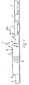
- a device designated overall by 1 for calibrating an initially still plastic hollow plastic profile emerging from an extrusion press the possible total height H of which is indicated only schematically in FIG. 3 and the possible total width L of which is indicated schematically in FIG Embodiment two openable dry calibration parts 2 and 3 and a vacuum tank 4 or the like vacuum container arranged behind it in the feed direction according to arrow Pf 1 in FIG. 1 of the profile.
- the profile is filled with liquid, in particular water, or optionally with gas under negative pressure.
- an opening 7 corresponding to the profile contour cf. inlet opening 7 in FIG. 2 is provided for the passage of the profile, these inlet and outlet opening 7 is arranged in an interchangeable part in order to be able to be adapted to changing contours of the profiles to be produced.
- a seal is arranged at these inlet and outlet openings 7, where some play is required between the continuous profile and the edges of these openings.
- this seal in such a way that the dry calibration part 3 in front of it can be opened quickly and unhindered, especially when inserting the start of the profile, so that the start of the profile can be easily inserted, to seal the inlet opening 7 and the outlet opening for the profile
- a liquid basin 8 is provided on the outside of the vacuum tank 4, the filling level of which is arranged above the highest points of the inlet opening 7 or the outlet opening and thus above the uppermost edge of the profile.
- the filling of the liquid pool 8 thus exceeds the upper limit of the greatest height H of the profile shown in FIG. 3.
- the filling of the liquid pool. 8 is expediently water, because this is harmless and inexpensive and nevertheless enables a good seal at the gaps between the profile and the openings 7.
- Water as a barrier liquid is particularly advantageous if the cooling of the profile within the vacuum tank 4 also takes place with water, because small amounts of the blocking water filling get from the basin 8 into the interior of the vacuum tank 4 due to the negative pressure in the vacuum tank 4. You can easily mix with the cooling water there.
- the first liquid pool 8 in the feed direction on the vacuum tank 4 on its wall 9 facing the dry calibration part 3 has a cutout 11 receiving the end face 10 of this calibration part 3 and one against the end face 10 by means of a seal 12 Plate 13, which in turn has a preferably upwardly open recess 14 for the passage of the profile and can be moved away from the dry calibration part 3.
- the dry calibration part 3 can thus be opened without problems in order to be able to insert the beginning of a profile to be calibrated quickly and easily.
- the plate 13 which can be placed tightly on the end face 10 of the dry calibration part 3 for closing off the water basin 8 is designed as a pivotable flap hinged below the lower edge of the dry calibration part 3 by means of a hinge, upper edge can be releasably locked by means of bolts 15 a in the closed position with respect to the pool wall 9.
- the plate 13 When the device 1 is started up for the first time, the plate 13 can easily be folded into the interior of the water basin 8, whereby the opening of the dry calibration part 3 is no longer hindered in any way.
- all these measures required when starting can be carried out quickly and easily, with the further passage of the profile then the closing of this flap 13 and the dry calibration part 3 can be carried out just as easily and quickly, so that the initial scrap of the profile due to the speed of this activities as necessary at the beginning kept as low as possible can be.
- the vacuum tank at the inlet and outlet opening 7 is also sealed so that the vacuum can be applied with high efficiency.
- the vacuum tank 4 preferably has an openable, gas-tight lid 16 on its top, which is also closed during operation, but is open when threading the beginning of the profile.
- the interior of the vacuum tank 4 there can be at least one holding disc, not shown in the drawing, which can have a recess which is exactly aligned with the inlet opening 7 and the outlet opening, in accordance with the outer contour of the profile to be produced. This is particularly advantageous in the case of a longer vacuum tank 4, because then the profile is supported even better during its still plastic phase within the vacuum tank and is kept in its desired shape.
- Fig. 1 it is indicated that that at least one water drain 17 is provided in the vacuum tank 4, which is arranged above the top edge of the profile to be produced and the highest point of the inlet opening 7, the suction opening 18 for connecting a vacuum pump or other vacuum generator is higher than this water drain 17. This ensures that the continuous profile is constantly surrounded on all sides by water and is therefore cooled as evenly as possible.
- Both the liquid basin 8 and the vacuum tank 4 can each have a water inlet, which is not shown in the drawing.
- fresh water can be continuously supplied through the water inlet, which then runs off again at the overflow 17 after heating by the profile.
- the cooling temperature within the vacuum tank 4 can thus be influenced to a certain extent by the speed of the water supply and the amount of water supplied.
- the water supply to the liquid basin 8 compensates for the amount of water that enters the vacuum tank 4 at the inlet and outlet openings 7 for the profile.
- the water outlet is expediently arranged in the lower region of the vacuum chamber 4 below the lowermost edge of the profile.
- two dry calibration parts 2 and 3 are connected in series in front of the vacuum tank 4 in the exemplary embodiment. It can be seen that a liquid basin 8 is also arranged as a transition between the two dry calibration parts 2 and 3, which thus also increases the efficiency of the vacuum device acting on the dry calibration parts 2 and 3 in a known manner by means of a better seal in this area.
- the water inlet (not shown) to the vacuum container 4 at the rear area in the feed direction and the water outlet 17 in the manner shown are arranged near the inlet opening 7 for the profile, so that the cooler water enters in the area where the profile also has already cooled down more. At the entrance of the still very warm profile this water is then warmed up somewhat, so that excessive quenching of the profile inside the vacuum container 4 is avoided.
- This gradual cooling of the profile within the vacuum tank 4 can be improved or configured in such a way that the length of the vacuum tank 4 in the in Fig.
- each compartment of the vacuum tank 4 then expediently having its own water inlet and outlet.
- the device 1 allows a quick threading and closing of the individual parts that are important for calibration, such as, in particular, the dry calibration parts and the transitions to the vacuum tank, while still providing the best possible seal, especially for the vacuum tank, so that a sufficiently high negative pressure is present inside it with good efficiency can be maintained even if the profile to be calibrated has a complicated contour provided with hook-shaped webs and the like, which would cause correspondingly long passage gaps at the inlet opening and the outlet opening.
Landscapes
- Engineering & Computer Science (AREA)
- Mechanical Engineering (AREA)
- Physics & Mathematics (AREA)
- Thermal Sciences (AREA)
- Extrusion Moulding Of Plastics Or The Like (AREA)
- Drying Of Solid Materials (AREA)
Abstract
Eine Vorrichtung (1) zum Kalibrieren eines aus einer Strangpresse austretenden, zunächst noch plastischen, hohlen Kunststoffprofiles hat wenigstens einen öffenbaren trockenen Kalibrierteil (2, 3) und einen in Vorschubrichtung des Profiles dahinter angeordneten Vakuumtank (4), innerhalb welchem das Profil unter Unterdruck mit Flüssigkeit, vorzugsweise Wasser oder gegebenenfalls auch Gas gekühlt wird. Sowohl am Eintritt als auch am Austritt des Vakuumtanks (4) ist jeweils eine der Profilkontur entsprechende Öffnung (7) für den Durchtritt des Profiles vorgesehen, die gegenüber dem Profil etwas Spiel haben kann oder soll. Zur Abdichtung der Eintrittsöffnung (7) und der Austrittsöffnung für das Profil ist deshalb außen am Vakuumtank (4) jeweils ein Flüssigkeitsbecken (8) vorgesehen, dessen Füllungsniveau über den höchsten Stellen der Eintrittsöffnung (7) bzw. der Austrittsöffnung angeordnet ist, so daß auch komplizierte Profile bearbeitet und dennoch ein Verlust an Unterdruck im Inneren des Vakuumtanks (4) so gering wie möglich gehalten wird.
Description
- Die Erfindung betrifft eine Vorrichtung zum Kalibrieren eines aus einer Strangpresse austretenden, zunächst noch plastischen, hohlen Kunststoffprofiles, mit wenigstens einem öffenbaren trockenen Kalibrierteil und einem in Vorschubrichtung des Profiles dahinter angeordneten Vakuumtank od. dgl., innerhalb welchem das Profil unter Unterdruck mit Flüssigkeit, vorzugsweise Wasser, gekühlt wird,' wobei sowohl am Eintritt als auch am Austritt des Vakuumtankes jeweils eine der Profilkontur entsprechende Öffnung für den Durchtritt des Profiles vorgesehen ist.
- Eine derartige Vorrichtung ist aus der DE-OS 34 27 277 bekannt. Dabei ist zwischen zwei trockenen Kalibrierteilen ein Vakuumtank angeordnet, in welchem das Hohlprofil zusätzlich mit Flüssigkeit gekühlt werden kann, wobei der Unterdruck in diesem Tank dafür sorgen soll, daß das noch plastische Profil seine Außenkontur beibehält. Durch diesen Vakuumtank soll die Abkühlung und Erhärtung beschleunigt und somit die Leistungsfähiigkeit der gesamten Vorrichtung vergrößert werden.
- Schwierigkeiten bereitet jedoch bei dieser vorveröffentlichten Vorrichtung die Anfahr-Phase, bei welcher der. erste Teil eines Profiles zunächst einmal in die gesamte Kalibriervorrichtung eingefädelt werden muß. Dazu können zwar die trockenen Kalibrierteile geöffnet werden, jedoch ergeben sich in dem Verbindungsbereich zu dem Vakuumtank Schwierigkeiten, weil die bei der DE-OS 34 27 277 vorgesehenen Flanschverbindungen dazu in irgendeiner Weise gelöst werden müssen.
- Dabei ist zu beachten, daß der einzulegende Profilanfang während des anschließenden Schließens der Kalibrierteile ständig mit der vorschubgeschwindigkeit weiterläuft. Es ist deshalb bei der vorveröffentlichten Vorrichtung mit einem erheblichen Ausschuß zu Beginn eines jeden Kalibriervorganges insbesondere dann zu rechnen, wenn die zu fertigenden Profile einen komplizierten Querschnitt mit mehreren Hohlräumen, Abwinklungen und dgl. haben.
- Eine weitere Schwierigkeit bei der Vorrichtung gemäß der DE-OS 34 27 277 ist darin zu sehen, daß der Vakuumtank nur begrenzt unter Unterdruck gesetzt werden kann, da die Eintritts- und Austrittsöffnungen für das Profil nie ganz dicht sein können. Es muß ein gewisses geringfügiges Spiel in diesen Öffnungen vorgesehen werden, um ein Verklemmen und Festsetzen der hindurchzuziehenden Profile zu vermeiden. An diesen Stellen kann nun ständig Luft in das Innere des Vakuumtankes einströmen, so daß selbst bei leistungsfähigen Unterdruck-Erzeugern nur eine relativ geringe Druckverminderung möglich ist. Somit ist die bestmögliche Formerhaltung des Profiles innerhalb dem Vakuumtank nicht sichergestellt. Dadurch wird wiederum die Leistungsfähigkeit der gesamten Vorrichtung beeinträchtigt und die Gefahr von Ausschuß erhöht.
- Es besteht deshalb die Aufgabe, eine Vorrichtung der eingangs erwähnten Art zu schaffen, bei welcher in dem Vakuumtank ein verbesserter Unterdruck möglich ist, gleichzeitig aber auch das Einlegen des Profilanfanges erleichtert und beschleunigt ist, so daß insgesamt die Gefahr von Ausschuß bei höherer Leistung vermindert ist.
- Die Lösung dieser Aufgabe besteht im wesentlichen darin, daß zur Abdichtung der Eintrittsöffnung und der Austrittsöffnung für das Profil außen am Vakuumtank jeweils ein Flüssigkeitsbecken vorgesehen ist, dessen Füllungsniveau über den höchsten Stellen der Eintrittsöffnung bzw- der Austrittsöffnung angeordnet ist.
- Versuche haben gezeigt, daß durch eine solche Flüssigkeitssperre unmittelbar vor und hinter dem Vakuumtank die an der Eintritts- und Austrittsöffnung erforderlichen geringfügigen Spalte gegenüber dem hindurchlaufenden Profil so sicher abgedichtet werden können, daß eine Vakuumpumpe oder ein Unterdruck-Erzeuger mit wesentlich größerem Wirkungsgrad an dem Vakuumtank eingesetzt werden kann. Entsprechend sicherer wird das Hohlprofil im Inneren dieses Vakuumtankes in seiner Form erhalten und kann gleichzeitig in diesem Bereich mit Flüssigkeit gekühlt werden, so daß die Durchlaufgeschwindigkeit des Profiles durch die Kalibriervorrichtung entsprechend erhöht werden kann.
- Gleichzeitig wird das erste Einlegen erleichtert, da der trockene Kalibrierteil nicht unmittelbar und möglichst dicht an den Vakuumtank angeschlossen sein muß, sondern den der Flüssigkeitssperre entsprechenden Abstand hat und seinerseits nur an dieser Flüssigkeitssperre dicht angeschlossen sein muß. Dadurch ergibt sich die Möglichkeit, beim Anfahren zunächst den Beginn des Profiles bei geöffnetem trockenem Kalibrierteil und noch ungefülltem Flüssigkeitsbecken einzulegen und durch den Vakuumtank hindurchzuziehen, bis dieser Profi.lanfang von einer an sich bekannten Abziehvorrichtung erfaßt ist. Danach kann der trockene Kalibrierteil auf einfache Weise geschlossen und in seine gegenüber der Flüssigkeitssperre dichte Position gebracht, dann das Wasserbecken zur Bildung der Flüssigkeitssperre gefüllt werden, wonach bereits die gesamte Vorrichtung im Normalbetrieb laufen kann. Zuvor oder zwischenzeitlich kann auch der Vakuumtank dicht geschlossen und mit Wasser gefüllt werden. Entsprechend kurz ist diese Anlaufzeit der gesamten Vorrichtung, so daß der zu Beginn notwendige Ausschuß des Profiles ebenfalls nur kurz ist.
- Die Füllung der Flüssigkeitsbecken ist zweckmäßigerweise Wasser, so daß bei einem Übertritt von Abdichtflüssigkeit aus dieser Flüssigkeitssperre in den Vakuumtank dort problemlos eine Vermischung mit der in der Regel von Wasser gebildeten Kühlflüssigkeit möglich ist.
- Das in Vorschubrichtung erste Flüssigkeitsbecken am Vakuumtank kann an seiner dem trockenen Kalibrierteil zugewandten Wandung einen die Stirnseite dieses Kalibrierteiles aufnehmenden Ausschnitt und eine gegen die Stirnseite mittels einer Dichtung od. dgl. anlegbare Platte aufweisen, die ihrerseits einen Ausschnitt für den Durchtritt des Profiles hat und von dem trockenen Kalibrierteil wegbewegbar ist. Dadurch ist es möglich, bei wegbewegter Platte und offenem trockenem Kalibrierteil den Profilanfang sehr leicht einzufädeln und durch das Flüssigkeitsbecken hindurchzulegen, wonach dann die anlegbare Platte gegen die Stirnseite des trockenen Kalibrierteiles angelegt wird und somit bereits die Verbindung zwischen trockenem Kalibrierteil und Wasserbecken hergestellt ist.
- Dieser Abdichtvorgang zwischen dem trockenen Kalibrierteil und der von einem Wasserbecken gebildeten Flüssigkeitssperre kann dadurch beschleunigt und vereinfacht werden, daß die an der Stirnseite des trockenen Kalibrierteiles dicht anlegbare Platte zum Abschließen des Wasserbeckens gegen den trockenen Kalibrierteil hin als schwenkbare, unterhalb der Unterkante des trockenen Kalibrierteiles angelenkte Klappe ausgebildet ist. Somit braucht diese Platte nur zum Inneren des Beckens hin verschwenkt zu werden, um das öffnen und wieder. Schließen des Kalibrierteiles auf einfache Weise zu erlauben, wobei nämlich in bekannter Weise die obere Hälfte des Kalibrierteiles nach oben bewegt oder geklappt wird. Durch die zuvor weggeschwenkte Klappe ist somit im Bereich der dem trockenen Kalibrierteil zugewandten Wandung des Wasserbeckens kein störendes Element mehr vorhanden, so daß das öffnen und Schließen des trockenen Kalibrierteiles entsprechend schnell und einfach durchzuführen ist.
- Im Inneren des Vakuumtanks kann vor allem bei relativ großer Länge dieses Tanks wenigstens eine Haltescheibe vorgesehen sein, die eine mit der Eintrittsö.ffnung und der Austrittsöffnung genau fluchtende Aussparung entsprechend der Außenkontur des herzustellenden Profiles haben kann. Bei noch größerer Länge des Vakuumtankes können auch mehrere derartige Haltescheiben vorgesehen sein, die dann mit ihren Aussparungen ebenfalls genau miteinander fluchten.
- Der Vakuumtank kann einen öffenbaren, gasdicht verschließbaren.Deckel vorzugsweise an seiner Oberseite aufweisen. Dadurch ist das Einfädeln des Profilanfanges von oben her möglich, ohne die erforderliche Füllhöhe im Inneren des Vakuumtanks zu beeinträchtigen.
- Bei einer Ausführungsform der erfindungsgemäßen Vorrichtung, bei welcher das herzustellende Profil innerhalb des Vakuumtanks durch ein es umschließendes Wasserbad laufen soll, ist es zweckmäßig, wenn in dem Vakuumtank wenigstens ein Wasserablauf vorgesehen ist, der oberhalb der obersten Kante des herzustellenden Profiles und der höchsten Stellen der Eintritts- und Austrittsöffnung angeordnet ist und wenn die Saugöffnung zum Anschluß einer Vakuumpumpe od. dgl. Unterdruck-Erzeuger höher als der Wasserablauf liegt. Ferner ist es dabei zweckmäßig, wenn die Flüssigkeitsbecken und der Vakuumtank je einen Wasserzulauf haben. Innerhalb das Vakuumtankes kann dann ständig frisches Wasser zulaufen und durch das abzukühlende Profil erwärmtes Wasser ablaufen, so daß eine gleichbleibende Temperatur innerhalb des Vakuumtanks aufrechterhalten werden kann. Gleichzeitig kann der Flüssigkeitsverlust in den abdichtenden Flüssigkeitsbecken ausgeglichen werden, der durch ein gewisses Einsaugen von Flüssigkeit in das Innere des Vakuumtankes entstehen kann.
- Dabei sei an dieser Stelle bemerkt, daß die Flüssigkeitsbecken je nach ihrer Ausdehnung neben ihrer Hauptaufgabe, den Vakuumtank gasdicht am Eintritt und Austritt des Pro-, files abzudichten, noch den zusätzlichen Zweck erfüllen, zur Abkühlung des Profiles beizutragen.
- Bei einer abgewandelten Ausführungsform kann als Wasserzulauf im Vakuumtank eine Sprühvorrichtung vorgesehen sein, wobei dann ein Wasserablauf vorzugsweise im unteren Bereich der Vakuumkammer unterhalb der untersten Kante des Profiles angeordnet ist.
- Eine weitere Verringerung der Gefahr von Ausschuß kann darin bestehen, daß vor dem Vakuumtank zwei trockene Kalibrierteile hintereinandergeschaltet sind und als Übergang zwischen den beiden trockenen Kalibrierteilen ein Flüssigkeitsbecken angeordnet ist. Dieses kann dann die trockenen Kalibrierteile, an denen ebenfalls ein Unterdruck angelegt ist, abdichten, so daß der Wirkungsgrad auch der die trockenen Kalibrierteile bedienenden Vakuumpumpe oder Unterdruck-Erzeuger ebenso verbessert wird, wie der für'die Unterdruckerzeugung am Vakuumtank.
- Eine weitere Ausgestaltung der Erfindung kann darin bestehen, daß der Wasserzulauf zum Vakuumbehälter am in Vorschubrichtung hinteren Bereich und der Wasserablauf nahe der Eintrittsöffnung für das Profil angeordnet sein kann. Somit wird in dem Bereich, in welchem das Profil schon am stärksten abgekühlt ist, das frische und kältere Wasser eingeführt, welches dann dort und in seinem weiteren Strömungsverlauf zu dem Ablauf hin durch das Profil etwas angewärmt wird, so daß der wärmere Teil des Profiles am Eintritt in den Vakuumtank auch mit etwas wärmerem Wasser beaufschlagt und somit die Abschreckung des Profiles verringert wird. Dadurch können zu schnelle und heftige Erstarrungen mit den daraus resultierenden Gefahren für das Profil vermieden werden.
- Eine weitere oder zusätzliche Ausgestaltung der Erfindung kann darin bestehen, daß der Vakuumtank auf seine Länge wenigstens einmal bis über Profilhöhe wasserdicht unterteilt ist und im in Vorschubrichtung ersten Bereich mit wärmerem Wasser als in Vorschubrichtung dahinter beschickt ist, wobei jeder abgeteilte Bereich des Vakuumtanks vorzugsweise einen eigenen Wasserzu- und -ablauf hat. Dies erlaubt es, in dem Bereich, den das Profil innerhalb des Vakuumtanks zuerst durchläuft, mit wärmerem Wasser zu beschicken als den oder die folgenden Bereiche, um so die zweckmäßige abgestufte allmähliche Abkühlung des Profiles zu erreichen. Dadurch kann wiederum die Gefahr von Ausschuß vermindert und die Leistung der gesamten Vorrichtung erhöht werden.
- Vor allem bei Kombination der vorbeschriebenen Merkmale und Maßnahmen ergibt sich eine Vorrichtung zum Kalibrieren, bei welcher die Vorteile eines Vakuumtankes zugunsten einer Vielzahl hintereinanderge-' schalteter trockener Kalibrierteile ausgenutzt werden können, ohne die bisherigen Nachteile beim Einfädeln des Profilanfanges und der relativ schwierigen Abdichtung bzw. ungenügenden Unterdruckerzeugung innerhalb des Vakuumtanks in Kauf zu nehmen. Dies wird in erster Linie durch die außen am Eintritt und am Austritt des Vakuumtanks befindlichen abdichtenden Flüssigkeitsbecken erreicht, die somit die Vergrößerung des Vakuumtankes bei dennoch guter Unterdruckwirkung in seinem Inneren erlauben, so daß sogar mehrere Bereiche unterschiedlicher Wassertemperaturen im Inneren des Vakuumtankes angeordnet werden können und insbesondere dem Vakuumtank nachgeschaltete zusätzliche Trockenkalibrierteile, wie sie gemäß der DE-OS 34 27-277 bisher notwendig waren, vermieden werden können.
- Nachstehend ist die Erfindung mit ihren ihr als wesentlich zugehörenden Einzelheiten anhand der Zeichnung noch näher beschrieben. Es zeigt in zum Teil schematisierter Darstellung
- Fig. 1 eine Seitenansicht.einer Vorrichtung zum Kalibrieren mit zwei hintereinander angeordneten trockenen Kalibrierteilen und einem sich daran anschließenden Vakuumtank,
- Fig. 2 in schaubildlicher Darstellung und in vergrößertem Maßstab den Übergang von einem . trockenen Kalibrierteil zu dem Vakuumtank mit einem dazwischen angeordneten Flüssigkeitsbecken zur Erzeugung einer abdichtenden Flüssigkeitssperre am Eintritt in den Vakuumtank, wobei die analoge Ausbildung eines Flüssigkeitstanks am Austritt aus dem Vakuumtank der besseren Übersicht wegen weggelassen ist,
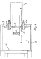
- Fig. 3 .einen Längsschnitt durch den Anschluß des trockenen Kalibrierteiles an das Flüssigkeitsbecken gemäß der Schnittlinie A-B in Fig. 4 und
- Fig. 4 eine Draufsicht des Flüssigkeitsbeckens am Eintritt in den Vakuumtank.
- Eine im ganzen mit 1 bezeichnete Vorrichtung zum Kalibrieren eines aus einer nicht näher dargestellten Strangpresse austretenden, zunächst noch plastischen, hohlen Kunststoffprofiles, dessen mögliche Gesamthöhe H lediglich schematisch in Fig. 3 und dessen mögliche Gesamtbreite L schematisch in Fig. 4 angedeutet ist, weist im Ausführungsbeispiel zwei öffenbare trockene Kalibrierteile 2 und 3 und einen in Vorschubrichtung gemäß dem Pfeil Pf 1 in Fig. 1 des Profiles dahinter angeordneten Vakuumtank 4 od. dgl. Vakuumbehälter auf. Innerhalb dieses Vakuumtanks 4 wird das Profil unter Unterdruck mit Flüssigkeit, insbesondere Wasser, oder gegebenenfalls mit Gas gefüllt. Dabei ist sowohl am Eintritt 5 als auch am Austritt 6 des Vakuumtanks 4 jeweils eine der Profilkontur entsprechende Öffnung 7 (vergl. Eintrittsöffnung 7 in Fig. 2) für den Durchtritt des Profiles vorgesehen, wobei diese Eintritts- und Austrittsöffnung 7 in einem jeweils auswechselbaren Teil angeordnet ist, um an wechselnde Konturen der herzustellenden Profile angepaßt werden zu-können.
- Um mit möglichst wenig Leistung dennoch innerhalb des Vakuumtanks 4 einen ausreichenden Unterdruck herstellen zu können, ist vorgesehen, daß an diesen Eintritts- und Austrittsöffnungen 7, wo zwischen dem durchlaufenden Profil und den Rändern dieser öffnungen etwas Spiel erforderlich ist, eine Abdichtung angeordnet ist. Um diese Abdichtung so zu gestalten, daß vor allem beim ersten Einführen des Profilanfanges vor allem der davor befindliche trockene Kalibrierteil 3 schnell und ungehindert geöffnet werden kann, damit der Profilanfang einfach eingeführt werden kann, ist zur Abdichtung der Eintrittsöffnung 7 und der Austrittsöffnung für das Profil außen am Vakuumtank 4 jeweils ein Flüssigkeitsbecken 8 vorgesehen, dessen Füllungsniveau über den höchsten Stellen der Eintrittsöffnung 7 bzw. der Austrittsöffnung und somit über der obersten Kante des Profiles angeordnet ist. Die Füllung des Flüssigkeitsbeckens 8 übertrifft also die in Fig. 3 dargestellte obere Begrenzung der größten Höhe H des Profiles. Die Füllung der Flüssigkeitsbecken. 8 ist dabei zweckmäßigerweise Wasser, weil dieses ungefährlich und preiswert ist und dennoch eine gute Abdichtung an den Spalten zwischen Profil und Öffnungen 7 ermöglicht. Dabei ist Wasser als Sperrflüssigkeit besonders vorteilhaft, wenn die Kühlung des Profiles innerhalb des Vakuumtanks 4 ebenfalls mit Wasser erfolgt, weil durch den Unterdruck im Vakuumtank 4 geringe Mengen der sperrenden Wasserfüllung aus den Becken 8 in das Innere des Vakuumtanks 4 gelangen. Sie können sich dort problemlos mit dem Kühlwasser mischen.
- In den Fig. 2 bis 4 erkennt man, daß das in Vorschubrichtung erste Flüssigkeitsbecken 8 am Vakuumtank 4 an seiner dem trockenen Kalibrierteil 3 zugewandten Wandung 9 einen die Stirnseite 10 dieses Kalibrierteiles 3 aufnehmenden Ausschnitt 11 und eine gegen die Stirnseite 10 mittels einer Dichtung 12 anlegbare Platte 13 aufweist, die ihrerseits eine vorzugsweise nach oben offene Ausnehmung 14 für den Durchtritt des Profiles hat und von dem trockenen Kalibrierteil 3 wegbewegbar ist. Bei wegbewegter Platte 13 kann somit der trockene Kalibrierteil 3 problemlos geöffnet werden, um den Anfang eines zu kalibrierenden Profiles gut und schnell einlegen zu können.
- In Fig. 3 erkennt man dabEi, daß die an der Stirnseite 10 des trockenen Kalibrierteiles 3 dicht anlegbare Platte 13 zum Abschließen des Wasserbeckens 8 als schwenkbare, unterhalb der Unterkante des trockenen Kalibrierteiles 3 mittels einem Scharnier 15 angelenkte Klappe ausgebildet ist, die am oberen Rand mittels Bolzen 15 a in Schließstellung gegenüber der Beckenwand 9 lösbar verriegelbar ist.
- Beim ersten Anfahren der Vorrichtung 1 kann also auf einfache Weise die Platte 13 in das Innere des Wasserbeckens 8 geklappt werden, wodurch das öffnen des trockenen Kalibrierteiles 3 in keiner Weise mehr behindert wird. Somit können all diese beim Anfahren erforderlichen Maßnahmen schnell und einfach durchgeführt werden, wobei beim weiteren Durchlauf des Profiles dann das Schließen dieser Klappe 13 und des trockenen Kalibrierteiles 3 ebenso einfach und schnell durchführbar sind, so daß der Anfangs-Ausschuß des Proffiles aufgrund der Schnelligkeit dieser zu Beginn notwendigen Tätigkeiten so gering wie möglich gehalten werden kann. Nach dem Füllen des nun dichten Wasserbeckens 8 ist außerdem der Vakuumtank an der Eintritts- und Austrittsöffnung 7 so abgedichtet, daß das Vakuum mit hohem Wirkungsgrad angelegt werden kann. Dabei erkennt man in Fig. 2, daß der Vakuumtank 4 einen öffenbaren, gasdicht verschließbaren Deckel 16 vorzugsweise an seiner Oberseite aufweist, der während des laufenden Betriebes ebenfalls geschlossen ist, aber beim Einfädeln des Profilanfanges geöffnet ist.
- Es sei noch erwähnt, daß im Inneren des Vakuumtankes 4 wenigstens eine in der Zeichnung nicht näher dargestellte Haltescheibe vorgesehen sein kann, die eine mit der Eintrittsöffnung 7 und der Austrittsöffnung genau fluchtende Aussparung entsprechend der Außen - kontur des herzustellenden Profiles haben kann. Dies ist vor allem bei einem längeren Vakuumtank 4 vorteilhaft, weil dann das Profil während seiner noch plastischen Phase innerhalb des Vakuumtanks noch besser gestützt und in seiner gewünschten Form gehalten wird.
- In Fig .1 ist angedeutet,-daß in dem Vakuumtank 4 wenigstens ein Wasserablauf 17 vorgesehen ist, der oberhalb der obersten Kante des herzustellenden Profiles und der höchsten Stelle der Eintrittsöffnung 7 angeordnet ist, wobei die Saugöffnung 18 zum Anschluß einer Vakuumpumpe oder eines sonstigen Unterdruckerzeugers höher als dieser Wasserablauf 17 liegt. Dadurch wird sichergestellt, daß das durchlaufende Profil ständig allseits von Wasser umschlossen ist und somit so gleichmäßig wie möglich gekühlt wird.
- Sowohl die Flüssigkeitsbecken 8 als auch der Vakuumtank 4 können je einen Wasserzulauf haben, der in der Zeichnung aber nicht näher dargestellt ist. Im Vakuumtank kann durch den Wasserzulauf ständig frisches Wasser zugeführt werden, welches dann an dem Überlauf 17 nach der Erwärmung durch das Profil wieder abläuft. Durch die Schnelligkeit des Wasserzulaufes und die zugeführte Wassermenge kann also in gewissem Umfang die Kühltemperatur innerhalb des Vakuumtanks 4 beeinflußt werden. Der Wasserzulauf zu den Flüssigkeitsbecken 8 gleicht jeweils die Wassermenge aus, die an den Eintritts- und Austrittsöffnungen 7 für das Profil in den Vakuumtank 4 gelangt.
- Falls als Wasserzulauf im Vakuumtank 4 eine Sprühvorrichtung vorgesehen ist, ist der Wasserablauf zweckmäßigerweise, im unteren Bereich der Vakuumkammer 4 unterhalb der untersten Kante des Profiles angeordnet.
- Wie bereits erwähnt, sind im Ausführungsbeispiel vor dem Vakuumtank 4 zwei trockene Kalibrierteile 2 und 3 hintereinander geschaltet. Dabei erkennt man, daß als Übergang zwischen den beiden trockenen Kalibrierteilen 2 und 3 ebenfalls ein Flüssigkeitsbecken 8 angeordnet ist, welches somit den Wirkungsgrad der an den trockenen Kalibrierteilen 2 und 3 in bekannter Weise angreifenden Vakuumeinrichtung ebenfalls durch eine bessere Abdichtung in diesem Bereich erhöht.
- Es sei noch erwähnt, daß der nicht näher dargestellte Wasserzulauf zum Vakuumbehälter 4 am in Vorschubrichtung hinteren Bereich und der Wasserablauf 17 in dargestellter Weise nahe der Eintrittsöffnung 7 für das Profil angeordnet sind, so daß das kühlere Wasser in dem Bereich zutritt, wo das Profil auch schon stärker abgekühlt ist. Am Eintritt des noch sehr warmen Profiles ist dieses Wasser dann schon etwas angewärmt, so daß ein zu starkes Abschrecken des Profiles innerhalb das Vakuumbehälters 4 vermieden wird. Diese allmählichere Abkühlung des Profiles innerhalb des Vakuumtanks 4 kann dadurch noch verbessert oder ausgestaltet sein, daß der Vakuumtank 4 auf seine Länge in der in Fig. 1 durch eine gestrichelt angedeutete Zwischenwand 19 wenigstens einmal bis über Profilhöhe wasserdicht unterteilt sein kann, wobei dann im in Vorschubrichtung vorderen oder zuerst von dem Profil erreichten Bereich mit wärmerem Wasser als im Vorschubbereich dahinter gekühlt werden kann, wobei jeder abgeteilte Bereich des Vakuumtanks 4 dann zweckmäßigerweise einen eigenen Wasserzulauf und einen eigenen Wasserablauf.17 hat.
- Insgesamt erlaubt die Vorrichtung 1 ein schnelles Einfädeln und Schließen der einzelnen für das Kalibrieren wichtigen Teile wie vor allem der trockenen Kalibrierteile und der Übergänge zum Vakuumtank bei dennoch bestmöglicher Abdichtung vor allem des Vakuumtanks, so daß in dessen Inneren mit gutem Wirkungsgrad ein ausreichend hoher'Unterdruck aufrecht erhalten bleiben kann, selbst wenn das zu kalibrierende Profil eine komplizierte, mit hakenförmigen Stegen und dergleichen versehene Kontur hat, die entsprechend lange Durchtrittsspalte an der Eintrittsöffnung und der Austrittsöffnung verursachen würde.
- Alle in der Beschreibung, den Ansprüchen und der Zeichnung dargestellten Merkmale und Konstruktionsdetails können sowohl einzeln als auch in beliebiger Kombination miteinander wesentliche Bedeutung haben.
Claims (12)
1. Vorrichtung zum Kalibrieren eines aus einer Strangpresse austretenden, zunächst noch plastischen hohlen Kunststoffprofiles, mit wenigstens einem öffenbaren, trockenen Kalibrierteil und einem in Vorschubrichtung des Profiles dahinter angeordneten Vakuumtank od. dgl., innerhalb welchem das Profil unter Unterdruck mit Flüssigkeit, vorzugsweise Wasser oder Gas gekühlt wird, wobei sowohl am Eintritt als auch am Austritt des Vakuumtankes jeweils eine der Profilkontur entsprechende Öffnung für den Durchtritt des Profiles vorgesehen ist, da - durch gekennzeichnet , daß zur Abdichtung der Eintrittsöffnung (7) und der Austrittsöffnung für das Profil außen am Vakuumtank (4) jeweils ein Flüssigkeitsbecken (8) vorgesehen ist, dessen Füllungsniveau über den höchsten Stellen der Eintrittsöffnung (7) bzw. der Austrittsöffnung angeordnet ist.
2. Vorrichtung nach Anspruch 1, dadurch gekennzeichnet, daß die Füllung der Flüssigkeitsbecken (8) Wasser ist.
3. Vorrichtung nach Anspruch 1 oder 2, dadurch gekennzeichnet, daß das in Vorschubrichtung erste Flüssigkeitsbecken (8) am Vakuumtank (4) an seiner dem trockenen Kalibrierteil (3) zugewandten Wandung (9) einen die Stirnseite (10) dieses Kalibrierteiles (3) aufnehmenden Ausschnitt (11) und eine gegen die Stirnseite (10) des Kalibrierteiles mittels einer Dichtung (12) od. dgl. anlegbare Platte (13) aufweist, die ihrerseits eine vorzugsweise nach oben offene Ausnehmung (14) für den Durchtritt des Profiles hat und von dem trockenen Kalibrierteil (3) wegbewegbar ist.
4. Vorrichtung nach einem der Ansprüche 1 bi 3, dadurch gekennzeichnet, daß die an der Stirnseite (10) des trockenen Kalibrierteiles (3) dicht anlegbare Platte (13) zum Abschließen des Wasserbeckens (8) als schwenkbare, unterhalb der Unterkante des trockenen Kalibrierteiles (3) angelenkte Klappe ausgebildet ist.
5. Vorrichtung nach einem der Ansprüche 1 bis 4, dadurch gekennzeichnet, daß im Inneren des Vakuumtanks (4) wenigstens eine Haltescheibe vorgesehen ist, die eine mit der Eintrittsöffnung (7) und der Austrittsöffnung genau fluchtende Aussparung entsprechend der Außenkontur des herzustellenden Profiles hat.
6. Vorrichtung nach einem der Ansprüche 1 bis 5, dadurch gekennzeichnet, daß der Vakuumtank (4) einen'öffenbaren, gasdicht verschließbaren Deckel (16) vorzugsweise an seiner Oberseite aufweist.
7. Vorrichtung nach einem der Ansprüche 1 bis 6, dadurch gekennzeichnet, daß in dem-Vakuumtank (4) wenigstens ein Wasserablauf vorgesehen ist, der oberhalb der obersten Kante des herzustellenden Profiles und der höchsten Stellen der Eintritts- und Austrittsöffnung (7) angeordnet ist und daß die Saugöffnung (18) zum Anschluß einer Vakuumpumpe od. dgl. Unterdruck-Erzeuger höher als der Wasserablauf (17) liegt.
8. Vorrichtung nach einem der Ansprüche 1 bis 7, dadurch gekennzeichnet, daß die Flüssigkeitsbecken (8) und der Vakuumtank (4) je einen Wasserzulauf haben.
9. Vorrichtung nach einem der Ansprüche 1 bis 8, dadurch gekennzeichnet, daß als Wasserzulauf im Vakuumtank (4) eine Sprühvorrichtung vorgesehen ist und ein Wasserablauf vorzugsweise im unteren Bereich der.Vakuumkammer (4) unterhalb der untersten Kante des Profiles angeordnet ist.
10. Vorrichtung nach einem der Ansprüche 1 bis 9, dadurch gekennzeichnet, daß vor dem Vakuumtank (4) zwei trockene Kalibrierteile (2, 3) hintereinander geschaltet sind und als übergang zwischen den beiden trockenen Kalibrierteilen (2, 3) ein Flüssigkeitsbecken (8) angeordnet ist.
11. Vorrichtung nach einem der Ansprüche 1 bis 10, dadurch gekennzeichnet, daß der Wasserzulauf zum Vakuumbehälter (4) am in Vorschubrichtung unteren Bereich und der Wasserablauf (17) nahe der Eintrittsöffnung (7) für das Profil angeordnet sind.
12. Vorrichtung nach einem der Ansprüche 1 bis 11., dadurch gekennzeichnet, daß der Vakuumtank (4) auf seine Länge wenigstens einmal bis über Profilhöhe wasserdicht unterteilt ist und im in Vorschubrichtung ersten Bereich mit wärmerem Wasser als in Vorschubrichtung dahinter beschickt ist, wobei jeder abgeteilte Bereich des Vakuumtanks (4) vorzugsweise einen eigenen Wasserzu- und -ablauf (17) hat.
Applications Claiming Priority (2)
| Application Number | Priority Date | Filing Date | Title |
|---|---|---|---|
| DE3618656 | 1986-06-03 | ||
| DE19863618656 DE3618656A1 (de) | 1986-06-03 | 1986-06-03 | Vorrichtung zum kalibrieren eines hohlen kunststoffprofiles |
Publications (2)
| Publication Number | Publication Date |
|---|---|
| EP0248280A2 true EP0248280A2 (de) | 1987-12-09 |
| EP0248280A3 EP0248280A3 (de) | 1988-11-09 |
Family
ID=6302195
Family Applications (1)
| Application Number | Title | Priority Date | Filing Date |
|---|---|---|---|
| EP87107386A Withdrawn EP0248280A3 (de) | 1986-06-03 | 1987-05-21 | Vorrichtung zum Kalibrieren eines hohlen Kunststoffprofiles |
Country Status (2)
| Country | Link |
|---|---|
| EP (1) | EP0248280A3 (de) |
| DE (1) | DE3618656A1 (de) |
Cited By (5)
| Publication number | Priority date | Publication date | Assignee | Title |
|---|---|---|---|---|
| WO1997029899A1 (de) * | 1996-02-13 | 1997-08-21 | C.A. Greiner & Söhne Gesellschaft M.B.H. | Verfahren und vorrichtung zum kühlen und gegebenenfalls kalibrieren von gegenständen aus kunststoff |
| WO1997046366A1 (de) * | 1996-06-04 | 1997-12-11 | Gebrüder Kömmerling Kunststoffwerke Gmbh | Vorrichtung zum abkühlen und kalibrieren extrudierter kunststoffprofile |
| US6488873B1 (en) | 1999-11-29 | 2002-12-03 | The Conair Group, Inc. | Apparatus and method for producing and cutting extruded material using temperature feedback |
| US6620354B1 (en) | 1999-11-29 | 2003-09-16 | The Conair Group, Inc. | Apparatus and method for producing and cutting extruded material using temperature feedback |
| EP2052840A3 (de) * | 2007-10-23 | 2012-11-14 | INOEX GmbH | Stufenlos einstellbare Kalibrierhülse für extrudierte Kunststoffrohre |
Families Citing this family (3)
| Publication number | Priority date | Publication date | Assignee | Title |
|---|---|---|---|---|
| DE10258813A1 (de) * | 2002-12-17 | 2004-07-08 | Krauss-Maffei Kunststofftechnik Gmbh | Anfahrsystem zur Verwendung bei einem Extruder |
| DE10306425B4 (de) * | 2003-02-15 | 2006-12-28 | Lüers, Gregor | Einrichtung zur Abdichtung des Ein- oder Auslasses einer Behandlungsstrecke |
| DE102005015683A1 (de) * | 2005-04-06 | 2006-10-12 | Inoex Gmbh | Abdichtung am Ausgang eines Unterdruck-Kalibrierbades |
Family Cites Families (15)
| Publication number | Priority date | Publication date | Assignee | Title |
|---|---|---|---|---|
| US2991501A (en) * | 1959-06-10 | 1961-07-11 | Justin H Ramsey | Vulcanizing chamber seal |
| US3184791A (en) * | 1962-08-17 | 1965-05-25 | Union Carbide Corp | Apparatus for fabrication of thermoplastic resins |
| US3169272A (en) * | 1962-10-30 | 1965-02-16 | Continental Oil Co | Apparatus for making plastic tubing |
| US3277656A (en) * | 1965-06-16 | 1966-10-11 | Western Electric Co | Methods and apparatus for cooling plastic articles |
| US3528210A (en) * | 1968-11-12 | 1970-09-15 | John E Johnson | Manhole grate |
| US3854527A (en) * | 1972-09-01 | 1974-12-17 | E Maroschak | Apparatus and method for fabricating corrugated plastic tubing |
| US3804574A (en) * | 1972-12-07 | 1974-04-16 | C Gatto | Apparatus for sizing shaped articles |
| FR2322724A1 (fr) * | 1975-09-02 | 1977-04-01 | Lacan Jacques | Appareil de calibrage a depression |
| CH617128A5 (en) * | 1977-05-26 | 1980-05-14 | Maillefer Sa | Method for cooling a tube or a profile made from plastic coming out of an extrusion head, and device for implementing the method |
| CH611549A5 (en) * | 1977-05-26 | 1979-06-15 | Maillefer Sa | Sizing device for an installation for cooling an extruded plastic tube |
| CH643481A5 (fr) * | 1981-12-21 | 1984-06-15 | Maillefer Sa | Dispositif pour le calibrage d'un tube en matiere plastique produit par extrusion. |
| DE3301556A1 (de) * | 1983-01-19 | 1984-07-19 | Battenfeld Extrusionstechnik GmbH, 4970 Bad Oeynhausen | Vorrichtung zum kalibrieren von extrudierten kunststoffprofilen |
| IT1163851B (it) * | 1983-07-26 | 1987-04-08 | Milani Resine Spa | Apparecchiatura per la calibratura di profilati estrusi di materia plastica |
| US4508500A (en) * | 1983-11-03 | 1985-04-02 | Tamaqua Cable Products Corporation | Electrical duct extrusion apparatus |
| JPS6135928A (ja) * | 1984-07-30 | 1986-02-20 | Mitsubishi Kasei Vinyl Co | 熱可塑性樹脂製パイプの製造方法 |
-
1986
- 1986-06-03 DE DE19863618656 patent/DE3618656A1/de active Granted
-
1987
- 1987-05-21 EP EP87107386A patent/EP0248280A3/de not_active Withdrawn
Cited By (9)
| Publication number | Priority date | Publication date | Assignee | Title |
|---|---|---|---|---|
| WO1997029899A1 (de) * | 1996-02-13 | 1997-08-21 | C.A. Greiner & Söhne Gesellschaft M.B.H. | Verfahren und vorrichtung zum kühlen und gegebenenfalls kalibrieren von gegenständen aus kunststoff |
| GB2326125A (en) * | 1996-02-13 | 1998-12-16 | Greiner & Soehne C A | Process and device for cooling and, optionally,calibrating of objects made of plastic |
| US6066288A (en) * | 1996-02-13 | 2000-05-23 | C. A. Greiner & Sohne Gesellschaft Mbh. | Method for cooling and if necessary calibrating articles of plastic |
| GB2326125B (en) * | 1996-02-13 | 2000-09-13 | Greiner & Soehne C A | Method for cooling and if necessary calibrating articles of plastic |
| DE19780093B4 (de) * | 1996-02-13 | 2005-12-01 | C.A. Greiner & Söhne Ges.m.b.H. | Verfahren und Vorrichtung zum Kühlen und gegebenenfalls Kalibrieren von Gegenständen aus Kunststoff |
| WO1997046366A1 (de) * | 1996-06-04 | 1997-12-11 | Gebrüder Kömmerling Kunststoffwerke Gmbh | Vorrichtung zum abkühlen und kalibrieren extrudierter kunststoffprofile |
| US6488873B1 (en) | 1999-11-29 | 2002-12-03 | The Conair Group, Inc. | Apparatus and method for producing and cutting extruded material using temperature feedback |
| US6620354B1 (en) | 1999-11-29 | 2003-09-16 | The Conair Group, Inc. | Apparatus and method for producing and cutting extruded material using temperature feedback |
| EP2052840A3 (de) * | 2007-10-23 | 2012-11-14 | INOEX GmbH | Stufenlos einstellbare Kalibrierhülse für extrudierte Kunststoffrohre |
Also Published As
| Publication number | Publication date |
|---|---|
| EP0248280A3 (de) | 1988-11-09 |
| DE3618656C2 (de) | 1988-06-01 |
| DE3618656A1 (de) | 1987-12-10 |
Similar Documents
| Publication | Publication Date | Title |
|---|---|---|
| DE2756193A1 (de) | Druckbehaeltereinheit und ein verfahren zum betrieb einer druckbehaeltereinheit | |
| DE2804982A1 (de) | Anordnung zum zufuehren eines kohaerenten kuehlfluessigkeits-vorhanges | |
| DE3427277A1 (de) | Einrichtung zum kalibrieren von strangpressprofilen aus kunststoff | |
| DE2344658A1 (de) | Vorrichtung zum dimensionieren von extrudierten kunststoffgegenstaenden | |
| EP0248280A2 (de) | Vorrichtung zum Kalibrieren eines hohlen Kunststoffprofiles | |
| DE3209825A1 (de) | Verfahren und vorrichtung zum spritzgiessen von kunststoffspritzteilen | |
| DE2726560C2 (de) | Abtauvorrichtung für eine Kühl- oder Tiefkühlvitrine | |
| DE2320859A1 (de) | Verfahren und einrichtung zur herbeifuehrung von partikelwachstum in einer stroemenden fluessigkeitssuspension | |
| DE2506023A1 (de) | Behaelter fuer salzschmelzen, vorzugsweise zur modifizierung der eigenschaften von gegenstaenden aus glas, vitrokristallinem material oder gestein | |
| DE2005294A1 (de) | ||
| DE3611046C2 (de) | ||
| DE2532528C3 (de) | Verfahren zur Einstellung eines bestimmten Verteilungsgesetzes des Durchflusses in einem Mediumsstrom, Vorrichtung zur Durchführung des Verfahrens und Verwendung des Verfahrens bzw. der Vorrichtung | |
| DE4437180A1 (de) | Verfahren zum Betrieb eines Stoffauflaufes einer Papier- oder Kartonmaschine | |
| DE2936289C2 (de) | Schiffshebewerk | |
| EP0678583B1 (de) | Verfahren zur Fest-Flüssig-Extrahierung und Extraktionsturm zur Durchführung des Verfahrens | |
| DE3215248A1 (de) | Wasser-kuehlvorrichtung fuer bleche und baender | |
| DE3213153A1 (de) | Mischkopf | |
| DE2448630A1 (de) | Abdeckprofil fuer zulauf- bzw. ablaufkanaele in boden- und/oder wandflaechen von behaeltern und becken | |
| DE69734137T2 (de) | Methode und Geräte zum Einführen von durch Luft angetriebenem Material in einem Kanal oder einer Aussparung | |
| DE164423C (de) | ||
| DE3035228A1 (de) | Vorrichtung zum estrahieren von loeslichen bestandteilen aus feststoffen | |
| DE1431716A1 (de) | Behaelter fuer teilchenfoermiges Material und Verfahren zu dessen Herstellung | |
| AT148879B (de) | Einrichtung an Wasserdurchlässen von Schleusentoren. | |
| CH638471A5 (en) | Process for pasteurising sludge, in particular sewage sludge, and pasteurisation vessel for carrying out the process | |
| DE1949019A1 (de) | Verfahren und Vorrichtung beim Stranggiessen zum Einfuehren eines Anfahrstranges in eine Durchlaufkokille |
Legal Events
| Date | Code | Title | Description |
|---|---|---|---|
| PUAI | Public reference made under article 153(3) epc to a published international application that has entered the european phase |
Free format text: ORIGINAL CODE: 0009012 |
|
| AK | Designated contracting states |
Kind code of ref document: A2 Designated state(s): AT BE DE FR GB IT NL |
|
| PUAL | Search report despatched |
Free format text: ORIGINAL CODE: 0009013 |
|
| AK | Designated contracting states |
Kind code of ref document: A3 Designated state(s): AT BE DE FR GB IT NL |
|
| STAA | Information on the status of an ep patent application or granted ep patent |
Free format text: STATUS: THE APPLICATION IS DEEMED TO BE WITHDRAWN |
|
| 18D | Application deemed to be withdrawn |
Effective date: 19890510 |