EP0247650B1 - Système de commande de la vitesse d'un moteur - Google Patents
Système de commande de la vitesse d'un moteur Download PDFInfo
- Publication number
- EP0247650B1 EP0247650B1 EP87200769A EP87200769A EP0247650B1 EP 0247650 B1 EP0247650 B1 EP 0247650B1 EP 87200769 A EP87200769 A EP 87200769A EP 87200769 A EP87200769 A EP 87200769A EP 0247650 B1 EP0247650 B1 EP 0247650B1
- Authority
- EP
- European Patent Office
- Prior art keywords
- output
- signal
- interrupt
- storage means
- detector
- Prior art date
- Legal status (The legal status is an assumption and is not a legal conclusion. Google has not performed a legal analysis and makes no representation as to the accuracy of the status listed.)
- Expired - Lifetime
Links
- 230000004044 response Effects 0.000 claims description 21
- 239000004020 conductor Substances 0.000 claims description 18
- 238000012360 testing method Methods 0.000 claims description 16
- 230000007704 transition Effects 0.000 claims description 9
- 125000004122 cyclic group Chemical group 0.000 claims description 6
- 230000008878 coupling Effects 0.000 claims description 3
- 238000010168 coupling process Methods 0.000 claims description 3
- 238000005859 coupling reaction Methods 0.000 claims description 3
- 238000010304 firing Methods 0.000 description 21
- 230000000295 complement effect Effects 0.000 description 2
- 239000013078 crystal Substances 0.000 description 2
- 230000004048 modification Effects 0.000 description 2
- 238000012986 modification Methods 0.000 description 2
- 238000010586 diagram Methods 0.000 description 1
- 230000005611 electricity Effects 0.000 description 1
- 230000003993 interaction Effects 0.000 description 1
- 238000000034 method Methods 0.000 description 1
- 230000008569 process Effects 0.000 description 1
- 230000001360 synchronised effect Effects 0.000 description 1
Images

Classifications
-
- H—ELECTRICITY
- H02—GENERATION; CONVERSION OR DISTRIBUTION OF ELECTRIC POWER
- H02P—CONTROL OR REGULATION OF ELECTRIC MOTORS, ELECTRIC GENERATORS OR DYNAMO-ELECTRIC CONVERTERS; CONTROLLING TRANSFORMERS, REACTORS OR CHOKE COILS
- H02P25/00—Arrangements or methods for the control of AC motors characterised by the kind of AC motor or by structural details
- H02P25/02—Arrangements or methods for the control of AC motors characterised by the kind of AC motor or by structural details characterised by the kind of motor
- H02P25/10—Commutator motors, e.g. repulsion motors
- H02P25/14—Universal motors
- H02P25/145—Universal motors whereby the speed is regulated by measuring the motor speed and comparing it with a given physical value, speed feedback
-
- H—ELECTRICITY
- H02—GENERATION; CONVERSION OR DISTRIBUTION OF ELECTRIC POWER
- H02P—CONTROL OR REGULATION OF ELECTRIC MOTORS, ELECTRIC GENERATORS OR DYNAMO-ELECTRIC CONVERTERS; CONTROLLING TRANSFORMERS, REACTORS OR CHOKE COILS
- H02P23/00—Arrangements or methods for the control of AC motors characterised by a control method other than vector control
- H02P23/0077—Characterised by the use of a particular software algorithm
-
- Y—GENERAL TAGGING OF NEW TECHNOLOGICAL DEVELOPMENTS; GENERAL TAGGING OF CROSS-SECTIONAL TECHNOLOGIES SPANNING OVER SEVERAL SECTIONS OF THE IPC; TECHNICAL SUBJECTS COVERED BY FORMER USPC CROSS-REFERENCE ART COLLECTIONS [XRACs] AND DIGESTS
- Y10—TECHNICAL SUBJECTS COVERED BY FORMER USPC
- Y10S—TECHNICAL SUBJECTS COVERED BY FORMER USPC CROSS-REFERENCE ART COLLECTIONS [XRACs] AND DIGESTS
- Y10S388/00—Electricity: motor control systems
- Y10S388/907—Specific control circuit element or device
- Y10S388/912—Pulse or frequency counter
Definitions
- This invention relates to a speed control system for an a.c. electric motor which is connected in series with a controllable switch between first and second a.c. supply conductors, which system comprises a data processing system comprising a program store and a processor for processing digital data in accordance with program data contained in said program store, an output of the processing system being coupled to a control input of said switch, a detector having an input coupled to said supply conductors and an output coupled to an input of said data processing system for generating an output signal when zero potential occurs between said supply conductors, a tachogenerator having an input coupled to said motor and an output coupled to an interrupt signal input of said data processing system, and a counter having an input coupled to an output of a clock signal source and an output coupled to an interrupt signal input of said data processing system for generating an output signal when the count therein reaches a predetermined value, said program comprising a cyclic main program and first and second interrupt routines which are arranged to be performed in response to the generation of an output signal by said
- the invention provides a speed control system for an a.c. electric motor which is connected in series with a controllable switch between first and second a.c. supply conductors, which system comprises a data processing system comprising a program store and a processor for processing digital data in accordance with program data contained in said program store, an output of the processing system being coupled to a control input of said switch, a detector having an input coupled to said supply conductors and an output coupled to an input of said data processing system for generating an output signal when zero potential occurs between said supply conductors, a tachogenerator having an input coupled to said motor and an output coupled to an interrupt signal input of said data processing system, and a counter having an input coupled to an output of a clock signal source and an output coupled to an interrupt signal input of said data processing system for generating an output signal in response to the count therein reaching a predetermined value, said program comprising a cyclic main program and first and second interrupt routines which are arranged to be performed in response to the generation of an output signal by
- Some single-chip microcomputers e.g. those of the MAB8400 family available from Mullard Ltd., U.K. have a single counter/timer on-chip, this being clocked by the source which also controls the actual microcomputer, and generating an interrupt each time it overflows. Such overflows normally occur several times during each half-cycle of the a.c. public electricity supply.
- the aforesaid counter may comprise a first portion which is arranged to generate a signal at an output thereof each time this portion overflows, which output is coupled to an interrupt signal input of the data processing system, and a second portion constituted by further storage means for a digital representation of the number of output signals which have been generated by overflow of the first portion since the last output signal generated by the detector occurred.
- the first storage means may be arranged to store a representation in terms of a whole number of complete cycle periods of said first portion plus a fraction of a second complete cycle period.
- the further interrupt routine may be arranged to load the first portion of the counter with a value such that it will next overflow after a period of time equal to the said fraction of a complete cycle period and to reset the further storage means.
- a larger interrupt routine may be provided which includes the second interrupt routine and which is arranged to be performed in response to each overflow of the said first portion, which larger interrupt routine is arranged to initiate the second interrupt routine in response to the occurrence of exactly said whole number of complete cycle periods of said first portion since the first overflow of said first portion after the last output signal was generated by the detector, and to update the content of the further storage means.
- a speed control system for an a.c. electric motor 1 which is connected in series with a controllable switch 2 in the form of a triac between first and second a.c. supply conductors 3 and 4 comprises a data processing system 5.
- System 5 includes a single-chip microcomputer 6 which in conventional manner comprises a program store 7 and a digital data processor 8 for performing a program of processing operations on digital data in accordance with program data contained in the store 7. This program will be described more fully below.
- Microcomputer 6 is, in the present example, a member of the MAB 8400 family available from Mullard Ltd., U.K., and in consequence has but a single interrupt signal input INT /TO.
- the microcomputer 6 includes internally first, second, third, fourth and fifth storage means in the form of registers FAR, ZCSLTA, TISLZC, NTT and LTT respectively, further storage means in the form of registers ZCSLTA*, CTPLV, TIBF, PM*, PT and PMrespectively, and an 8-bit timer/counter CT which is driven by an internal clock CL the frequency of which is determined by an external crystal resonator 12 connected between pins XTAL 1 and XTAL 2 of the microcomputer 6.
- the clock CL also controls the overall operation of the microcomputer, with the result that counter CT is clocked once every machine cycle performed by the microcomputer. Each time the content of counter CT corresponds to its maximum count and receives a further clock pulse, i.e. overflows, it resets and generates an internal interrupt signal.
- Control of the speed of the motor 1 is effected by controlling the firing angle of triac 2, i.e. the instant in each half-cycle of the a.c. supply fed to the conductors 3 and 4 at which the triac 2 is fired, these instants being made earlier in the half cycles (corresponding to a larger firing angle) if the actual motor speed is less than a target speed a digital representation of which is stored in the register PT in microcomputer 6, and being made later in the half-cycles (corresponding to a smaller firing angle) if the actual speed is greater than the target speed.
- the trigger pulses for the triac 2 are generated by microcomputer 6 at the correct instants at a pair of parallel-connected output port pins PO10 and P011 and are fed to the triac gate via an amplifier 9.
- the microcomputer 6 needs information about when each zero crossing occurs in the supply fed to the conductors 3 and 4, i.e. when each half-cycle starts, and also about the actual speed of the motor 1.
- the system 5 also includes first and second interrupt signal sources in the form of a detector 10 for zero potential between the conductors 3 and 4, and a tachogenerator 11 driven by the motor 1.
- each of these sources produces logic "1" at its output, source 10 producing a logic "0" pulse each time the voltage between conductors 3 and 4 reaches zero and source 11 producing logic "0" pulses at a rate which is directly proportional to the speed of the motor 1.
- Source 10 may comprise a pair of voltage comparators for detecting the presence on one of the conductors 3 and 4 of a potential less than a very small positive and negative potential respectively relative to the other, the outputs of which comparators are combined by means of a NAND function).
- Each of these logic "0" pulses initiates an interrupt routine in the microcomputer 6, this routine comprising first and second branches, the first being taken in response to a logic "0" pulse from zero crossing detector 10 and the second being taken in response to a logic "0" pulse from tachogenerator 11.
- the outputs 13 and 14 of the sources 10 and 11 are coupled to respective inputs 15 and 16 of a OR-function circuit 17 the output 18 of which is connected to the interrupt signal input INT /TO of microcomputer 6.
- the coupling from output 13 to input 15 is via the set input 19 and the output 20 of a bistable device 21, and the coupling from output 14 to input 16 is via the set input 22 and the output 23 of a bistable device 24.
- Device 21 comprises in known manner two cross-coupled NAND-gates 25 and 26, and device 24 similarly comprises two cross-coupled NAND-gates 27 and 28.
- OR-function circuit 17 also has an override signal input 29 to which is connected a further output port pin PO16 of microcomputer 6.
- Two further output port pins PO6 and PO7 of microcomputer 6 are connected to reset inputs 31 and 32 respectively of bistable devices 21 and 24 respectively.
- the output 20 of bistable device 21 is also connected to a test input pin T1 of microcomputer 6.
- the bistable devices 21 and 24 and the disable input 29 of OR-function circuit 17 are provided for the following reason.
- Microcomputer 6 responds, at its interrupt signal input INT /TO, only to a signal transition from logic "1" to logic "0", and not to the mere presence thereat of logic "0". Because the logic "0" pulses from tachogenerator 11 can occur at any time during a cycle of the voltage supply fed to conductors 3 and 4 it is very possible that, at least occasionally, one of these will overlap a logic "0" pulse from zero-crossing detector 10.
- Output pin PO16 is normally logic "1", this output pin being connected to one input of a NAND-gate 34 forming part of circuit 17.
- the other input of NAND-gate 34 is fed from the outputs 20 and 23 of devices 21 and 24 via a NAND-gate 35 also forming part of circuit 17, so that if it is assumed that both devices initially produce a logic “1” a logic “0” subsequently produced by either of these devices (in response to a logic "0” pulse produced by the source 10 or the source 11) will result in the application of a signal transition from logic "1” to logic "0” to the interrupt signal input INT /TO, and hence in the carrying out of an interrupt routine by microcomputer 6.
- This interrupt routine includes the following steps.
- bistable device 21 is in the set state, indicating that zero-crossing detector 10 has produced a logic "0" pulse, and a first branch of the interrupt routine is taken. If the signal state at test input T1 is logic "1" on the other hand, then tachogenerator 11 must have produced the logic "0" pulse which gave rise to the interrupt, and a second branch of the interrupt routine is taken in this case.
- microcomputer 6 At the end of the first branch microcomputer 6 generates a logic "0" pulse at its output PO6, resetting bistable device 21, and also generates a logic "0" pulse at its output PO16.
- microcomputer 6 At the end of the second branch microcomputer 6 generates a logic "0" pulse at its output PO7, resetting bistable device 24, and also generates a logic "0" pulse at its output PO16. If only one of these bistable devices is in the set state when the reset occurs (because only one of the sources 10 and 11 has produced a logic "0" pulse) the signal level at interrupt signal input INT /TO merely returns to logic "1" and remains there until one of the bistable devices 21 and 24 again assumes the set state.
- test pin T1 is connected to the output of bistable device 21, if both the tachogenerator 11 and the mains zero crossing detector 10 produce a logic "0" pulse substantially simultaneously the interrupt routine branch corresponding to the zero-crossing detector 10 will be performed before the branch corresponding to the tachogenerator 11.
- An alternative possibility is to connect the output 23 of device 24 to a further test input of microcomputer 6, for example another pin of the port PO, and to arrange that this and pin T1 are tested in the required order at the beginning of the interrupt routine. This would be necessary in any case if one or more further interrupt signal sources and associated bistable devices were provided connected to further respective inputs of NAND-gate 35, as it will be evident is possible. If such a further source and associated device is present microcomputer 6 will obviously have to be provided with a corresponding further output similar to PO6 and PO7 connected to the reset input of the further bistable device.
- Fig. 1 operates as follows, it being assumed, for example, that crystal resonator 12 is chosen to resonate at such a frequency that counter CT is clocked at a frequency such that there are between five and seven complete fill (cycle) periods for this counter in each half-cycle of the a.c. voltage applied to conductors 3 and 4.
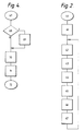
- Program store 7 contains a cyclic main program which basically consists of a calculation routine for calculating the actual speed of the motor 1 as indicated by the period of the output pulses of the tachogenerator 11 and, from this and the target speed indicated by the content of the register PT, the firing angle for the triac 2 required in each half-cycle of the a.c. supply fed to the conductors 3 and 4.
- This calculation results in an eleven-bit digital number indicating the number of counts which counter CT should make after each zero crossing occurs in the a.c. supply before the triac is fired, which number is stored in the firing angle register FAR.
- the three most significant bits of this number indicate the number of complete cycles of counter CT required and the eight least significant bits indicate the additional fraction of a complete cycle which is required.
- a digital number representing the period of the tachogenerator pulses and hence the actual speed of the motor is calculated from the content of the registers LTT, NTT and ZCSLTA* and entered into the register PM, and each time this occurs the previous content of register PM is entered into another register PM*.
- register NTT contains, at any given time, a representation in terms of a number of counts of counter CT of the time interval by which the last tachogenerator pulse lagged the zero-crossing in the a.c. supply which immediately preceded it.
- register LTT contains a representation of a similar quantity relating to the preceding tachogenerator pulse.
- register ZCSLTA* contains a representation of the number of zero-crossings (if any) which occurred between these two tachogenerator pulses.
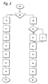
- pin T1 is first tested (step 49) to determine whether the interrupting device is the zero-crossing detector 10. If it is (branch "Y") the 8-bit counter CT and the register CTPLV are both set (steps 50 and 51) to the 256-complement of the eight least significant bits of the content of the firing angle register FAR which has previously been filled during the main program, as mentioned above. Moreover register TIBF is set in step 52 to the three most significant bits of the content of register FAR. In general triac 2 will be required to be fired a whole number N of cycles of counter CT plus a fraction of such a cycle after the zero-crossing instant, the contents of register FAR representing these quantities, as indicated above.
- step 50 counter CT will next overflow (generating a timer interrupt) after the said fraction of such a cycle, and because of step 52 the content of register TIBF indicates at which subsequent such overflow (or the same one) the triac should be fired.
- the content of register TIBF is first tested to see if it is zero, after which it is decremented. If the result of the test is zero the triac is actually fired, thus achieving the correct firing instant.
- the quantity stored in step 51 is used when the tachogenerator 11 produces an external interrupt, as will be described below.
- a record is kept in register TISLZC of the number of timer interrupts which have occurred since the last zero-crossing (again for use when the tachogenerator produces an external interrupt); this is the reason for step 53.
- a record is kept in register ZCSLTA of the number of zero-crossings which have occurred since the last tachogenerator interrupt (again for use when the tachogenerator produces an interrupt); this is the reason for step 54.
- the logic "0" pulse generated on pin P06 by means of steps 55 and 56 resets the bistable device 21.
- step 49 If it is determined in step 49 that the zero-crossing detector 10 is not the interrupting device, then the interrupting device must be the tachogenerator 11. In such a case branch "N" is carried out. More particularly, in step 58 the content of register NTT is transferred to register LTT. Then in step 59 it is tested whether the content of counter CT is less than a predetermined amount L. If it is not ("N") then in step 60 register NTT is filled with a quantity given by the concatenated contents of register TISLZC and counter CT less the content of register CTPLV.
- step 53 Because of step 53 and of the fact (as will be described with reference to Figure 4) that the content of register TISLZC is incremented each time a timer interrupt occurs, at any given time the contents of register TISLZC indicate how many timer interrupts have occurred since the last zero-crossing.
- the concatenated contents of register TISLZC and counter CT therefore represent the number of clock pulses generated by clock CL since the last zero-crossing occurred, i.e. the time period between the immediately preceding zero-crossing and the current tachogenerator output pulse. This quantity is therefore entered into register NTT.
- step 58 a corresponding quantity relating to the immediately preceding tachogenerator output pulse is already present in register LTT.
- the time (represented by a number of output pulses of clock CL) elapsing between these two tachogenerator output pulses (which is a measure of the current motor speed) is therefore given by the content of register NTT less the content of register LTT plus X times the number of output pulses of CL which corresponds to a complete half-cycle of the supply applied across terminals 3 and 4, where X is the number of zero-crossings which have occurred since the tachogenerator produced the preceding output pulse.
- register ZCSLTA Because of steps 54 and 63 the quantity X is contained in register ZCSLTA, this quantity being saved into register ZCSLTA* in step 62.
- the registers NTT, LTT and ZCSLTA* contain the quantities required by step 46 in the main program.
- the logic "0" pulse generated on output pin P07 by means of steps 64 and 65 resets the bistable device 24.
- the logic "0" pulse generated on pin P016 by means of steps 64 and 65 temporarily overrides the output signal of OR-function circuit 17, as described above, thereby producing a new transition from logic "1" to logic "0" at interrupt input INT /TO if bistable device 21 should also be in the set state.
- step 60 is replaced by step 61, the difference being that the quantity 255 is used in the calculation instead of the content of counter CT.
- the relevant reading of counter CT will not follow the interrupt signal which gave rise to the relevant interrupt routine immediately, inter alia because the microcomputer 6 has first to store parameters to enable it to continue with its current program after the interrupt has been serviced, during which storage process the counter CT continues to count.
- the counter CT is thus read L counts after the interrupt signal occurs, where L may be of the order of ten, and thus the reading is too high by L. This does not normally matter, as it is the same for all readings.
- register TIBF is loaded in step 52 ( Figure 3) at each zero-crossing with the number of timer interrupts which should occur before the triac is actually fired, and is decremented (step 70) when each timer interrupt actually occurs, if when a given timer interrupt occurs the content of register TIBF is zero (test 68) then the triac should be fired immediately. This is accordingly done by means of step 69.
- a record is kept in register TISLZC of the number of timer interrupts which have occurred since the last zero-crossing (for use in steps 60 and 61 of Figure 3). This is the reason for the incrementing of the contents of this register in step 71 (and for their resetting to zero in step 53 of Figure 3).
- step 71 may be omitted provided that test 68 is now a test on the contents of register TISLZC for equality with the contents of register TIBF.
- steps 43, 45, 46 and 47 of the main program are only performed if a tachogenerator interrupt has been generated and processed by means of steps 58-66 since steps 43-47 were last performed. (Otherwise the main program would be duplicating a previous calculation).
- the branch of Figure 3 containing the steps 58-66 may include an operation (not shown) of setting a flag
- the main program of Figure 2 may include, after step 42, the steps (not shown) of testing and resetting this flag, the steps 43, 45, 46 and 47 only being performed if the flag is found to be set.
- step 58 of Figure 3 may be omitted if it is arranged that the results of the calculations carried out in step 60 (or 61) are written alternately into respective members of a pair of registers, a toggle being operated each time to indicate which register was last written and being tested in step 43 of Figure 2 to indicate which register corresponds to NTT and which to LTT.
- steps 43, 45 and 46 of the main program of Figure 2 can be carried out instead in the interrupt branch containing steps 58-66 of Figure 3, step 44 of Figure 2 then being transferred to after step 47.
- registers TIBF and TISLZC may be omitted, the various calculations and operations involving the contents of these registers being suitably modified or omitted accordingly.
Landscapes
- Engineering & Computer Science (AREA)
- Power Engineering (AREA)
- Control Of Ac Motors In General (AREA)
- Control Of Electric Motors In General (AREA)
Claims (4)
- Système (5) de réglage de la vitesse d'un moteur électrique à courant alternatif (1) monté en série avec un commutateur commandable (2) entre des premier et second conducteurs d'alimentation de courant alternatif (3, 4), comportant
un système de traitement de données (6) comportant une mémoire de programme (7) et un (8) processeur pour traiter des données numériques selon des données de programme contenues dans ladite mémoire de programme (7), une sortie (PO10, PO11) du système de traitement étant couplée à une entrée de commande dudit commutateur (2),
un détecteur (10) ayant une entrée couplée auxdits conducteurs d'alimentation (3, 4) et une sortie (13) couplée à une entrée ()T1 dudit système de traitement de données (6) pour engendrer un signal de sortie lors de l'apparition du potentiel zéro entre lesdits conducteurs d'alimentation (3,4),
un générateur tachymétrique (11) ayant une entrée couplée audit moteur (1) et une sortie (14) couplée à une entrée de signal d'interruption (INT /T0) dudit système de traitement de données (6), et
un compteur (CT) ayant une entrée couplée à une sortie de la source de signal d'horloge (CL) et une sortie couplée à une entrée de signal d'interruption dudit système de traitement de données (6) pour engendrer un signal de sortie lorsque ce compteur atteint une position de valeur prédéterminée, ledit programme comportant un programme principal cyclique (40, 47) et des premier (58-66) et second (69-72) sous-programmes d'interruption conçus pour être exécutés respectivement en réaction à la génération d'un signal de sortie par ledit générateur tachymétrique (11) et en réaction au fait que ledit compteur (CT) a atteint ladite position de valeur prédéterminée, caractérisé en ce que la sortie (19) du détecteur est couplée à une entrée de signal d'interruption (INT /T0) dudit système de traitement de données (6), en ce que ledit programme comporte un autre sous-programme d'interruption (50-57) conçu pour être exécuté en réaction à la génération d'un signal de sortie par ledit détecteur (10), et en ce que ledit système de traitement (6) comporte des premiers moyens de mémorisation (FAR) pour mémoriser une représentation numérique, exprimée en nombre de comptages du compteur (CT), de la durée, comptée à partir de la génération d'un signal d'interruption par ledit détecteur (10), pendant laquelle le commutateur (2) doit être conducteur, des deuxièmes moyens de mémorisation (ZCSTLA) pour mémoriser une représentation numérique du nombre de signaux de sortie ayant été engendrés par ledit détecteur (10) depuis la génération d'un signal de sortie précédent par le générateur tachymétrique (11) et des troisième (NTT) et quatrième (LTT) moyens de mémorisation pour mémoriser les uns et les autres une représentation numérique d'une durée respective qui s'est écoulée entre la génération d'un signal de sortie par le détecteur (10) et la génération suivante d'un signal de sortie par le générateur tachymétrique (11), ou pour de l'information à partir de laquelle cette durée peut être calculée, ledit autre sous-programme d'interruption (50-57) étant conçu pour(a) introduire dans le compteur (CT) une valeur déduite des premiers moyens de mémorisation (FAR) de façon que le comptage de ce compteur atteindra ensuite ladite valeur prédéterminée lorsque le commutateur (2) doit être conducteur, et pour(b) mettre à jour le contenu des deuxièmes moyens de mémorisation (ZCSTLA),
ledit second sous-programme d'interruption (69-72) étant conçu pour(c) engendrer sur ladite sortie (P010, P011) du système de traitement (6) un signal de commande de conduction pour le commutateur (2),
ledit premier sous-programme d'interruption (58-66) étant conçu pour(d) lire le contenu du compteur (CT), déduire une représentation de la durée qui s'est écoulée depuis la génération d'un signal de sortie par le détecteur (10), à partir du contenu ainsi lu et de la valeur par laquelle le compteur (CT) a été chargé lors de la génération par le détecteur (10) du signal de sortie précédent et mémoriser la représentation dans les uns des troisième (NTT) et quatrième (LTT) moyens de mémorisation, de sorte que les uns des troisièmes (NTT) et quatrièmes (LTT) moyens de mémorisation contiennent la représentation et que les autres des troisième (NTT) et quatrième (LTT) moyens de mémorisation contiennent la représentation précédente et(e) pour sauvegarder le contenu des deuxièmes moyens de stockage (ZCSTLA) et les remettre à zéro,
le programme principal (40-47) étant conçu pour(f) calculer, à partir du contenu des troisième (NTT) et quatrième (LTT) moyens de mémorisation et du contenu de sauvegarder des deuxièmes moyens de mémorisation (ZCSTLA), la période des signaux de sortie engendrée par le générateur tachymétrique (11),(g) calculer, à partir d'au moins cette période et d'une quantité représentative de la vitesse exigée du moteur, une quantité, exprimée en nombre de comptages du compteur, représentative de la durée pendant laquelle, après la génération d'un signal de sortie par le détecteur (10), le commutateur (2) doit être conducteur et(h) mémoriser la durée calculée dans les premiers moyens de mémorisation (FAR). - Système (5) de réglage de la vitesse selon la revendication 1, caractérisé en ce que le compteur (CT) comporte une première partie conçue pour engendrer un signal sur une sortie de celle-ci chaque fois que cette partie déborde, sortie qui est couplée à une entrée de signal d'interruption du système de traitement de données (6), et une seconde partie constituée par d'autres moyens de mémorisation (TISLZC) pour une représentation numérique du nombre de signaux de sortie qui ont été engendrés par débordement de la première partie depuis l'apparition du dernier signal de sortie engendré par le détecteur (10), en ce que les premiers moyens de mémorisation (FAR) sont conçus pour mémoriser une représentation, exprimée par un nombre premier de périodes de cycle complètes de ladite première partie plus une fraction d'une deuxième période de cycle complètes, en ce que l'autre sous-programme d'interruption (50-57) est conçu pour charger la première partie du compteur d'une valeur telle que le débordement suivant du compteur s'effectue après une durée égale à ladite fraction d'une période cycle complète et pour remettre à zéro les autres moyens de stockage (TISLZC), et en ce qu'il est prévu un sous-programme d'interruption plus grand (67-72) comportant le second sous-programme d'interruption (69-72) et conçu pour être exécuté en réaction à chaque débordement de ladite première partie, sous-programme d'interruption plus grand (67, 72) qui est conçu pour lancer le second sous-programme d'interruption (69-72) en réaction à l'apparition dudit nombre entier précis de périodes de cycle complètes de ladite première partie depuis le premier débordement de ladite première partie après que le dernier signal de sortie a été engendré par le détecteur (10), et pour mettre à jour le contenu des autres moyens de mémorisation (TISLZC).
- Système (5) de réglage de la vitesse selon la revendication 1 ou 2, dans lequel les sorties dudit détecteur (10) et dudit générateur tachymétrique (11) sont toutes les deux couplées à la même entrée de signal d'interruption (
INT /TO) dudit système de traitement de données (6) à travers un circuit à fonction OU (17) pour appliquer un premier niveau de signal à ladite entrée de signal d'interruption (INT /TO) lorsque le générateur tachymétrique (11) ou le détecteur (10) engendre un signal de sortie, caractérisé en ce que les couplages des sorties du détecteur (10) et du générateur tachymétrique (11) au circuit à fonction OU (17) sont respectivement établis à travers des premier (21) et second (24) dispositifs bistables conçus chacun pour être amenés dans un premier état en réaction à la génération dudit signal de sortie correspondant, en ce que le premier dispositif bistable (21) a une sortie (20) couplée à une autre entrée (T1) dudit processeur de données (6), en ce que ledit processeur de données (6) est pourvu d'une sortie (PO6, PO7) reliée à chaque dispositif bistable (21, 24) pour ramener ce dispositif bistable dans un second état, en ce que ledit programme comporte un sous-programme d'interruption (48, 66) conçu pour être exécuté en réaction à un passage de signal d'un second niveau audit premier niveau sur ladite entrée de signal d'interruption (INT /TO)), sous-programme d'interruption (48-66) qui est conçu pour vérifier si le premier dispositif bistable (21) est dans son premier état et pour exécuter ledit autre sous-programme d'interruption (50-57) si le résultat de ladite vérification est positif et pour exécuter ledit premier sous-programme d'interruption (58-66) dans le cas contraire, en ce que ledit circuit à fonction OU (17) est pourvu d'au moins une entrée de signal prioritaire (29) de sorte que ledit second niveau de signal est appliqué à ladite entrée de signal d'interruption (INT /TO) lorsqu'un signal prioritaire est présent sur l'une quelconque desdites entrées de signal prioritaire (29), quel que soit l'état desdits dispositifs bistables (21, 24), en ce que ledit autre sous-programme d'interruption (50-57) est conçu pour appliquer un signal de remise à zéro audit premier dispositif bistable (21) et pour appliquer un signal prioritaire à ladite entrée de signal prioritaire (29) jusqu'après l'application dudit signal de remise à zéro audit premier dispositif bistable (21), et en ce que ledit premier sous-programme d'interruption (58-66) est conçu pour appliquer un signal de remise à zéro audit second dispositif bistable (24) et pour appliquer un signal prioritaire à ladite entrée de signal prioritaire (29) jusqu'après l'application dudit signal de remise à zéro audit second dispositif bistable (24). - Système selon la revendication 3, caractérisé en ce que ledit autre sous-programme d'interruption (50-57) est encore conçu pour appliquer un signal prioritaire à ladite entrée de signal prioritaire (29) jusqu'après l'application d'un signal de remise à zéro audit premier dispositif bistable (21) ou audit second dispositif bistable (24).
Applications Claiming Priority (2)
| Application Number | Priority Date | Filing Date | Title |
|---|---|---|---|
| GB8610565 | 1986-04-30 | ||
| GB08610565A GB2189910A (en) | 1986-04-30 | 1986-04-30 | Motor speed control system |
Publications (3)
| Publication Number | Publication Date |
|---|---|
| EP0247650A2 EP0247650A2 (fr) | 1987-12-02 |
| EP0247650A3 EP0247650A3 (en) | 1989-07-26 |
| EP0247650B1 true EP0247650B1 (fr) | 1993-08-04 |
Family
ID=10597115
Family Applications (1)
| Application Number | Title | Priority Date | Filing Date |
|---|---|---|---|
| EP87200769A Expired - Lifetime EP0247650B1 (fr) | 1986-04-30 | 1987-04-23 | Système de commande de la vitesse d'un moteur |
Country Status (5)
| Country | Link |
|---|---|
| US (1) | US4771223A (fr) |
| EP (1) | EP0247650B1 (fr) |
| JP (1) | JPS62262685A (fr) |
| DE (1) | DE3786837D1 (fr) |
| GB (1) | GB2189910A (fr) |
Families Citing this family (10)
| Publication number | Priority date | Publication date | Assignee | Title |
|---|---|---|---|---|
| JPH02159989A (ja) * | 1988-12-09 | 1990-06-20 | Sharp Corp | タイミング信号発生回路 |
| ES2018423A6 (es) * | 1989-11-14 | 1991-04-01 | Fagor S Copp Ltda | Regulador digital de velocidad para motor de lavadora. |
| FR2686168B1 (fr) * | 1992-01-14 | 1994-05-13 | Motorola Semiconducteurs Sa | Circuit de commande de la vitesse d'un moteur. |
| JP3458523B2 (ja) * | 1994-12-07 | 2003-10-20 | 三菱電機株式会社 | モータ装置・モータの駆動装置及びその制御方法 |
| GB2301716A (en) * | 1995-06-01 | 1996-12-11 | Yang Tai Her | Phase angle control circuit for a switching device |
| US5894095A (en) * | 1997-04-17 | 1999-04-13 | Demali; Gary W. | Mixing drill with speed sensing with multiple preset speeds |
| FR2767427B1 (fr) * | 1997-08-14 | 2000-04-28 | Moulinex Sa | Procede et systeme de variation et de regulation de vitesse d'un moteur |
| FR2767428B1 (fr) * | 1997-08-18 | 1999-11-19 | Moulinex Sa | Systeme et procede de regulation de vitesse pour moteur a excitation serie, et moteur correspondant |
| US7227326B1 (en) * | 2006-04-24 | 2007-06-05 | Rockwell Automation Technologies, Inc. | System and method for transient-based motor speed estimation with transient excitation |
| CN108336939B (zh) * | 2017-01-19 | 2023-03-24 | 尼得科电机有限公司 | 用于使用和控制永磁交流电动机的系统和方法 |
Family Cites Families (4)
| Publication number | Priority date | Publication date | Assignee | Title |
|---|---|---|---|---|
| US3110853A (en) * | 1958-06-05 | 1963-11-12 | Westinghouse Electric Corp | Electrical control apparatus |
| US4201936A (en) * | 1976-12-10 | 1980-05-06 | General Electric Company | Motor speed regulator and control system |
| AU2255583A (en) * | 1982-12-21 | 1984-06-28 | Sunbeam Corp. | Food preparation appliance |
| GB2147436A (en) * | 1983-09-28 | 1985-05-09 | Philips Electronic Associated | Variable motor speed control arrangement |
-
1986
- 1986-04-30 GB GB08610565A patent/GB2189910A/en not_active Withdrawn
-
1987
- 1987-04-21 US US07/040,910 patent/US4771223A/en not_active Expired - Fee Related
- 1987-04-23 EP EP87200769A patent/EP0247650B1/fr not_active Expired - Lifetime
- 1987-04-23 DE DE8787200769T patent/DE3786837D1/de not_active Expired - Lifetime
- 1987-04-30 JP JP62107885A patent/JPS62262685A/ja active Pending
Non-Patent Citations (1)
| Title |
|---|
| STEUER UND REGELTECHNIK NO: 14; 11TH OF July 1986, pages 73-78, München, D; H. SAX et al. : " Mikrocomputer mit sensor-und Aktuator-Interface. " * |
Also Published As
| Publication number | Publication date |
|---|---|
| JPS62262685A (ja) | 1987-11-14 |
| EP0247650A2 (fr) | 1987-12-02 |
| GB2189910A (en) | 1987-11-04 |
| EP0247650A3 (en) | 1989-07-26 |
| US4771223A (en) | 1988-09-13 |
| GB8610565D0 (en) | 1986-06-04 |
| DE3786837D1 (de) | 1993-09-09 |
Similar Documents
| Publication | Publication Date | Title |
|---|---|---|
| US4758945A (en) | Method for reducing power consumed by a static microprocessor | |
| US4748559A (en) | Apparatus for reducing power consumed by a static microprocessor | |
| JPH0795291B2 (ja) | ウオツチドツグタイマ | |
| US4771223A (en) | Motor speed control system | |
| EP0082558B1 (fr) | Dispositif générant un signal de commande d'interrupteurs à semi-conducteurs | |
| GB2189912A (en) | Data processing system; A.C. motor control | |
| JP2557785Y2 (ja) | シングルチップマイクロコンピュータ | |
| JPS63200234A (ja) | デ−タ処理装置 | |
| US4468133A (en) | Electronic timepiece | |
| JPH06188872A (ja) | 同期保護回路 | |
| JPS5916054A (ja) | マイクロ・プロセツサ | |
| JPS593563A (ja) | 計算機システム評価用タイマ | |
| JPH0573296A (ja) | マイクロコンピユータ | |
| SU1677858A1 (ru) | Асинхронный распределитель | |
| JPH0767288B2 (ja) | サイリスタ・インバ−タのゲ−トパルス制御装置 | |
| SU1164889A1 (ru) | Преобразователь частота-код | |
| SU1193668A1 (ru) | Устройство дл умножени | |
| JP2517943B2 (ja) | タイマ装置 | |
| CN116736786A (zh) | 一种实现plc控制设备计划任务队列的方法 | |
| JP2778066B2 (ja) | キャプチャ機構を有するマイクロプロセッサ | |
| JPH0695304B2 (ja) | デ−タ処理装置 | |
| JPH0113135B2 (fr) | ||
| JPS5935250A (ja) | プログラム制御装置 | |
| JPS62113245A (ja) | シグナルプロセサの動作監視装置 | |
| JPS63247805A (ja) | デイジタル制御装置のプログラム処理時間測定方式 |
Legal Events
| Date | Code | Title | Description |
|---|---|---|---|
| PUAI | Public reference made under article 153(3) epc to a published international application that has entered the european phase |
Free format text: ORIGINAL CODE: 0009012 |
|
| AK | Designated contracting states |
Kind code of ref document: A2 Designated state(s): DE ES FR GB IT |
|
| RAP3 | Party data changed (applicant data changed or rights of an application transferred) |
Owner name: PHILIPS ELECTRONIC AND ASSOCIATED INDUSTRIES LIMIT Owner name: N.V. PHILIPS' GLOEILAMPENFABRIEKEN |
|
| PUAL | Search report despatched |
Free format text: ORIGINAL CODE: 0009013 |
|
| AK | Designated contracting states |
Kind code of ref document: A3 Designated state(s): DE ES FR GB IT |
|
| 17P | Request for examination filed |
Effective date: 19900118 |
|
| 17Q | First examination report despatched |
Effective date: 19920211 |
|
| RAP3 | Party data changed (applicant data changed or rights of an application transferred) |
Owner name: PHILIPS ELECTRONICS UK LIMITED Owner name: N.V. PHILIPS' GLOEILAMPENFABRIEKEN |
|
| GRAA | (expected) grant |
Free format text: ORIGINAL CODE: 0009210 |
|
| AK | Designated contracting states |
Kind code of ref document: B1 Designated state(s): DE ES FR GB IT |
|
| PG25 | Lapsed in a contracting state [announced via postgrant information from national office to epo] |
Ref country code: IT Free format text: LAPSE BECAUSE OF FAILURE TO SUBMIT A TRANSLATION OF THE DESCRIPTION OR TO PAY THE FEE WITHIN THE PRE;WARNING: LAPSES OF ITALIAN PATENTS WITH EFFECTIVE DATE BEFORE 2007 MAY HAVE OCCURRED AT ANY TIME BEFORE 2007. THE CORRECT EFFECTIVE DATE MAY BE DIFFERENT FROM THE ONE RECORDED.SCRIBED TIME-LIMIT Effective date: 19930804 Ref country code: DE Effective date: 19930804 Ref country code: FR Effective date: 19930804 |
|
| REF | Corresponds to: |
Ref document number: 3786837 Country of ref document: DE Date of ref document: 19930909 |
|
| PG25 | Lapsed in a contracting state [announced via postgrant information from national office to epo] |
Ref country code: ES Free format text: LAPSE BECAUSE OF FAILURE TO SUBMIT A TRANSLATION OF THE DESCRIPTION OR TO PAY THE FEE WITHIN THE PRESCRIBED TIME-LIMIT Effective date: 19931115 |
|
| EN | Fr: translation not filed | ||
| PG25 | Lapsed in a contracting state [announced via postgrant information from national office to epo] |
Ref country code: GB Effective date: 19940423 |
|
| PLBE | No opposition filed within time limit |
Free format text: ORIGINAL CODE: 0009261 |
|
| STAA | Information on the status of an ep patent application or granted ep patent |
Free format text: STATUS: NO OPPOSITION FILED WITHIN TIME LIMIT |
|
| 26N | No opposition filed | ||
| GBPC | Gb: european patent ceased through non-payment of renewal fee |
Effective date: 19940423 |