EP0247301A2 - Asymmetrischer Spaltpolmotor - Google Patents
Asymmetrischer Spaltpolmotor Download PDFInfo
- Publication number
- EP0247301A2 EP0247301A2 EP87103420A EP87103420A EP0247301A2 EP 0247301 A2 EP0247301 A2 EP 0247301A2 EP 87103420 A EP87103420 A EP 87103420A EP 87103420 A EP87103420 A EP 87103420A EP 0247301 A2 EP0247301 A2 EP 0247301A2
- Authority
- EP
- European Patent Office
- Prior art keywords
- rotor
- stator
- shaded
- pole motor
- asymmetric
- Prior art date
- Legal status (The legal status is an assumption and is not a legal conclusion. Google has not performed a legal analysis and makes no representation as to the accuracy of the status listed.)
- Granted
Links
Images
Classifications
-
- H—ELECTRICITY
- H02—GENERATION; CONVERSION OR DISTRIBUTION OF ELECTRIC POWER
- H02K—DYNAMO-ELECTRIC MACHINES
- H02K5/00—Casings; Enclosures; Supports
- H02K5/04—Casings or enclosures characterised by the shape, form or construction thereof
- H02K5/16—Means for supporting bearings, e.g. insulating supports or means for fitting bearings in the bearing-shields
- H02K5/167—Means for supporting bearings, e.g. insulating supports or means for fitting bearings in the bearing-shields using sliding-contact or spherical cap bearings
- H02K5/1675—Means for supporting bearings, e.g. insulating supports or means for fitting bearings in the bearing-shields using sliding-contact or spherical cap bearings radially supporting the rotary shaft at only one end of the rotor
-
- H—ELECTRICITY
- H02—GENERATION; CONVERSION OR DISTRIBUTION OF ELECTRIC POWER
- H02K—DYNAMO-ELECTRIC MACHINES
- H02K1/00—Details of the magnetic circuit
- H02K1/06—Details of the magnetic circuit characterised by the shape, form or construction
- H02K1/12—Stationary parts of the magnetic circuit
- H02K1/18—Means for mounting or fastening magnetic stationary parts on to, or to, the stator structures
- H02K1/185—Means for mounting or fastening magnetic stationary parts on to, or to, the stator structures to outer stators
-
- H—ELECTRICITY
- H02—GENERATION; CONVERSION OR DISTRIBUTION OF ELECTRIC POWER
- H02K—DYNAMO-ELECTRIC MACHINES
- H02K17/00—Asynchronous induction motors; Asynchronous induction generators
- H02K17/02—Asynchronous induction motors
- H02K17/04—Asynchronous induction motors for single phase current
- H02K17/10—Motors with auxiliary phase obtained by split-pole carrying short-circuited windings
-
- H—ELECTRICITY
- H02—GENERATION; CONVERSION OR DISTRIBUTION OF ELECTRIC POWER
- H02K—DYNAMO-ELECTRIC MACHINES
- H02K17/00—Asynchronous induction motors; Asynchronous induction generators
- H02K17/02—Asynchronous induction motors
- H02K17/16—Asynchronous induction motors having rotors with internally short-circuited windings, e.g. cage rotors
-
- H—ELECTRICITY
- H02—GENERATION; CONVERSION OR DISTRIBUTION OF ELECTRIC POWER
- H02K—DYNAMO-ELECTRIC MACHINES
- H02K5/00—Casings; Enclosures; Supports
- H02K5/04—Casings or enclosures characterised by the shape, form or construction thereof
- H02K5/16—Means for supporting bearings, e.g. insulating supports or means for fitting bearings in the bearing-shields
- H02K5/173—Means for supporting bearings, e.g. insulating supports or means for fitting bearings in the bearing-shields using bearings with rolling contact, e.g. ball bearings
- H02K5/1735—Means for supporting bearings, e.g. insulating supports or means for fitting bearings in the bearing-shields using bearings with rolling contact, e.g. ball bearings radially supporting the rotary shaft at only one end of the rotor
Definitions
- the present invention relates to an asymmetrical shaded-pole motor with a stator made of a laminated laminated core formed from a C-shaped yoke, between whose free pliers legs a yoke web is pressed, on which a main winding is seated, and in the C-legs connecting the pliers legs, a short-circuited auxiliary winding and in one Recess of this leg a laminated squirrel-cage rotor with a small air gap to the stator are rotatably arranged on a motor shaft.
- Such a motor is already known from DE-OS 32 46 595.
- the shaft of the rotor is accommodated in a bore located in the center of the rotor laminated core.
- a bearing plate with integrated bearing elements which is screwed on both sides to the stator lamination stack, is used to fix the rotor attached to the shaft to the stator lamination stack.
- the present invention is based on the object, starting from an asymmetrical shaded-pole motor of the type described above, to improve it in such a way that a reliable mounting of the motor shaft without a curse tion error is given, as well as an improved heat dissipation from the storage area is achieved and unbalances caused by parts driven via the motor shaft can be better compensated for, so that the motor runs very smoothly.
- the object on which the present invention is based is to create a structurally simple, compact and inexpensive to produce motor construction, the same iron volume being present in the yoke with the same power as in the known shaded-pole motors.
- the squirrel-cage rotor is of hollow cylindrical design and directly coaxially surrounds a bearing support tube projecting into its interior from its open side and connected to the stator, in which the motor shaft is guided in bearings and at the end opposite the bearing support tube with the rotor connected is.
- a motor is therefore created which can be referred to as an intermediate rotor motor, since the rotor is arranged in a rotating manner between the bearing support tube of the stator and the stator laminated core.
- the invention is based on the surprising finding that, despite the rotor having an enlarged diameter compared to the rotors of the known asymmetrical split motors of the same power, the iron volume remains unchanged, and this even has the additional effect that the entire motor has a shorter overall length than motors of conventional design with the same performance. Because of the configuration according to the invention, it is possible for the motor flange to be received on the outer surface of the bearing support tube when machining the bearing bore and for the bearing seats on both sides, which are located in the interior of the bearing support tube, to be machined. As a result, a misalignment of the two bearings which affects the service life of the ball bearing is excluded. Also the Heat transfer from the shaft to the bearing elements is largely reduced according to the invention.
- a synchronous motor for use in electrical watches or the like, in which a permanent-magnetic rotor is rotatably arranged around a bearing shoulder of the stator, the stator itself being made of magnetizable material.
- This rotor is not suitable, for example, for driving hot air devices, since here the motor shaft on the rotor opposite end emerges from the stator, so that the bearing area is directly exposed to the influence of heat.
- the section receiving the bearings protrudes far from the stator on the side facing away from the rotor, so that the overall length increases and the bearing is not enclosed by the rotor, but lies outside the actual motor.
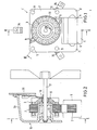
- FIG. 1 shows an asymmetrical shaded-pole motor 1 according to the invention.
- This shaded-pole motor consists of a dynamo sheet package as stator 2 and a rotor 3.
- the view shown in FIG. 1 shows the shaded-pole motor 1 according to the invention seen from the motor flange side.
- the rotor 3 is also made from a laminated core laminated from individual laminations.
- the stator 2 and the rotor 3 are manufactured based on the inventive design of the shaded-pole motor 1 in the so-called stamping compacting process.
- the stator is C-shaped and its yoke web 4 is designed as a separate part so that it can be removed. This results in the possibility of rational production of an excitation coil 5 (main winding) applied to the yoke.
- the stator has 2 auxiliary windings 9, which consist, for example, of bare, short-circuited copper windings.
- the auxiliary windings 9 are formed diagonally opposite one another on the circumference of the opening 3 accommodating the rotor 3 in the stator 2.
- Four bores 11 are preferably formed in the stator 2, which are arranged in the corners of a square, in particular a square, through the center of which the axis of rotation of the rotor 3 runs.
- the motor flange 12 which for Fastening of the motor is used, provided with a bearing support tube 13, wherein the bearing support tube 13 is preferably in one piece with the motor flange 12.
- This bearing support tube 13 runs coaxially to the rotor 3, which surrounds the bearing support tube 13 and preferably completely receives it.
- the rotor 3 is cup-shaped so that the bearing support tube 13 projects into the rotor 3 from the open side thereof.
- Bearing bodies 14 are arranged in the bearing support tube 13, preferably in each case in the two end regions of the bearing support tube 13. These bearing bodies 14 can consist of ball bearings, plain bearings or a combination of both.
- the bearing seats for the bearing body 14 can be machined from the inside in such a way that misalignments between the two bearing bodies are practically excluded.
- the bearing support tube 13 attached to the motor flange 12 is clamped on its outside and simultaneously machined on both sides of its inside.
- the hollow cylindrical rotor 3 has, at the end opposite the bearing support tube, a base 15 with a bushing 16, via which the rotor 3 is non-positively connected to a shaft 17.
- the rotor 3 consists of individual laminations laminated one on top of the other. In the motor according to the invention, as is known per se, these are connected to one another and to short-circuit rings at the end by a short-circuit winding which is made of aluminum or an aluminum alloy.
- the bottom 15 of the rotor 3 is preferably completely closed and can have cooling fins on its outside. Alternatively, it can also be formed from radial webs, between which the rotor base has openings for better cooling of the bearing elements. As shown in FIG.
- an additional cooling wheel can also be used in the case of particularly high thermal loads 20 can be arranged on the shaft 17 outside the motor according to the invention.
- the shaft 17 is mounted in a known manner inside the bearing support tube 13.
- the inventive construction of the motor 1 with the accommodation of the bearing within the rotor 3 results in excellent heat dissipation to the outside due to the radial enlargement of the rotor and the associated increase in mass. A thermal load on the bearing elements is largely avoided.
- an increase in the moment of inertia is achieved by this design according to the invention, which ensures a smooth running of the motor in balanced motors.
- any remaining unbalance, e.g. B. a mounted on the shaft fan 33 due to the increased mass moment of inertia of the rotor only to a reduced extent on the smooth running of the motor.
- evenly distributed bores can be provided in the circumferential direction on its two end faces.
- the stator 2 is fastened to the motor flange 12 by means of pins 21.
- These pins 21 run through the bores 11 of the stator 2, the laminated core forming the stator 2 being pushed up to a stop 22 which is formed on the pin 21.
- the end of the pins 21 is crimped after the stator laminated core has been pushed on, so that a flanged edge 23 is created by which the stator laminated core is held together. Due to this type of fastening of the stator laminated core according to the invention, it is possible to prefabricate it according to the punched packaging method. A additional measure such. B. welding, scrubbing or the like to hold the individual laminations of the stator laminated core together is not required.
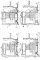
- 5 to 8 show further variants for fastening the stator laminated core.
- FIG. 5 shows a fastening of the laminated core forming the stator 2 by means of threaded screws 24, the threaded screws 24 being screwed into hollow cylinder lugs 25 of the motor flange 12 which have a corresponding internal thread.
- the cylinder lugs 25 are provided with a circumferential shoulder 26 at their free ends for centering and as an assembly aid for the laminated core of the stator, which protrudes into the bore in the stator laminated core.
- the bearing body 14 can for example be designed as a plain bearing.
- FIG. 6 shows a fastening of the stator laminated core using hollow rivets 27.
- These hollow rivets are riveted into the free ends of the pins 21.
- These hollow rivets 27 in turn serve to hold the stator laminated core together and to secure it.
- the bearing body 14 can for example be designed as a spherical bearing. Solid rivets can also be used instead of hollow rivets.
- FIG. 7 shows a fastening of the stator laminated core, which consists of a screw 28 which has a thread only in its front area and is otherwise cylindrical.
- the cylindrical region is longer than the height of the stator laminated core, so that the screw 28 projects with its cylindrical region from the stator laminated core and the cylindrical region is still received by the bore of the projection 25, which is why Approach 25 has a thread only in its lower region.
- the outside diameter of the cylindrical region of the screw 28 is only slightly smaller than the inside diameter of the bores 11 in the stator laminated core. This design according to the invention results in a centering of the stator when the screws 28 are inserted.
- the front end of the cylinder extension 25 serves as a stop for the stator laminated core, so that the stator laminated core is clamped between the screw head and this front end.
- the bearing of the shaft 17 can consist of a combination of plain bearings, in particular spherical bearings, and ball bearings. In this case, the slide bearing and the ball bearing will be arranged on the end facing the motor flange 12.
- FIG. 8 shows a further exemplary embodiment for fastening the stator laminated core, specifically by means of a threaded screw with a nut, the nut being arranged within the motor flange.
- the cylinder lug 25 has a centering shoulder 26 which engages in the bores 11 of the stator lamination stack.
- the cylinder extension 25 has a through hole.
- the shaft is supported by ball bearings.
- FIG. 4 shows a view of an engine according to the invention from the side of the engine bottle 12. The embodiment shown is used as a hot air blower.
- the motor flange 12 has three arc-shaped fastening arms 34 which are supported on a rear wall of a device, not shown.
- the motor flange is preferably made of die-cast aluminum when an increased thermal load z. B. when used for hot air blowers.
- the production from suitable plastic materials is also possible.
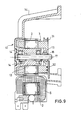
- FIG. 9 shows two further embodiment variants of an engine according to the invention.
- the basic structure of the mounting corresponds to the embodiment as described in FIG. 8.
- a pulley 31 is attached to the rotor 3.
- the motor according to the invention can serve as a drive unit.
- the pulley can also be formed in one piece with the rotor 3.
- FIG. 9 lower half, a variant is shown where a pulse generator disk 32 is attached to the end face of the rotor 3.
- the bottom half of FIG. 9 basically corresponds to the embodiment in FIG. 6.
- the rotor is freely accessible on the side facing away from the motor flange 12 and can therefore be used for a wide variety of drive, measurement and display purposes. It is also within the scope of the invention to provide the outside of the rotor with external teeth so that the rotor can be part of a gear drive.
- the present invention is not limited to the exemplary embodiments described, but encompasses all the embodiments having the same effect in the sense of the invention.
- the motor according to the invention has an extended output with the same power short leg lengths or pliers lengths of the laminated stator, but there is a significantly reduced thickness of the iron package, so that a very flat design is achieved. This is based on the knowledge that the motor according to the invention does not require an increase in the iron volume compared to known asymmetrical split motors of the same power, although the rotor provided according to the invention is enlarged in diameter compared to the rotors of known split pole motors of the same power.
Landscapes
- Engineering & Computer Science (AREA)
- Power Engineering (AREA)
- Iron Core Of Rotating Electric Machines (AREA)
- Motor Or Generator Frames (AREA)
- Fittings On The Vehicle Exterior For Carrying Loads, And Devices For Holding Or Mounting Articles (AREA)
- Dc Machiner (AREA)
Abstract
Description
- Die vorliegende Erfindung betrifft einen asymmetrischen Spaltpolmotor mit einem Stator aus einem lamellierten Blechpaket gebildet aus einem C-förmigen Joch zwischen dessen freien Zangenschenkeln ein Jochsteg eingepreßt ist, auf dem eine Hauptwicklung sitzt, und im die Zangenschenkel verbindenden C-Schenkel eine kurzgeschlossene Hilfswicklung und in einer Ausnehmung dieses Schenkels ein lamellierter Kurzschlußläuferrotor mit geringem Luftspalt zum Stator auf einer Motorwelle drehbar angeordnet sind.
- Aus der DE-OS 32 46 595 ist bereits ein derartiger Motor bekannt. Dabei ist die Welle des Rotors in einer sich im Zentrum des Rotorblechpaketes befindlichen Bohrung untergebracht. Zum Fixieren des auf der der Welle befestigten Rotors am Statorblechpaket dient ein beidseitig je am Statorblechpaket verschraubtes Lagerschild mit integrierten Lagerelementen. Bei dieser Anordnung von Welle und Lager ist der Durchmesser des Rotors relativ klein, und die axiale Länge des Motors wird durch die stirnseitig aufgesetzten Lagerschilde übermäßig vergrößert. Auf der Welle des Rotors ist beispielsweise ein Lüfterrad befestigbar.
- Bei derart bekanntnen Motoren, wie sie eingangs beschrieben sind, tritt das Problem auf, daß im Falle der Erhitzung der Rotorwelle durch äußere Einflüsse eine sehr hohe thermische Belastung auf das Lager einwirkt, was zu einem Ausfall der Lager und damit des Motors führen kann. Diese Probleme treten insbesondere bei Motoren auf, die zum Antrieb von Lüfterrädern verwendet werden, die Teile von Heißluftgebläsen in Back-, Grill- oder Bratgeräten sind. Durch die Erhitzung bzw. Aufheizung des Lüfterrades kommt ein Wärmefluß zustande, der ausgehend vom Lüfterrad über die Welle, die Lager und Lagerschilde zum Statorblechpaket führt. Dieser Wärmefluß über die LagereIemente kann zu einer Zersetzung des Öles bzw. des Fettes führen. Im äußersten Fall kann dies zu einem Trockenlaufen und damit zu einer Zerstörung des Lagers, zumindest aber zu einer wesentlichen Verminderung der Lebensdauer des Lagers führen. In dieser Hinsicht sind Gleitlagerausführungen besonders anfällig.
- Bei Kugellagerausführungen tritt diese thermische Belastung nicht im selben Maße in den Vordergrund wie bei Gleitlagern. Hier wirkt sich aber die mangelnde Möglichkeit der Justierbarkeit der Motorwelle aus. Da sich durch die jeweils stirnseitig auf das Statorblechpaket aufgesetzten und verschraubten Lagerschilde stets ein radialer Versatz der Welle ergibt, entsteht zwischen den beiden Lagerschilden ein Fluchtungsfehler, der vom Kugellager nicht ausgeglichen werden kann und deshalb lebensdauermindernd auf die Lager wirkt. Ein weiterer Nachteil dieser bekannten Innenläufermotoren besteht darin, daß sich aufgrund der relativ geringen Masse des Rotors Unwuchtprobleme von auf der Welle befestigten Teilen sehr stark bemerkbar machen. Dies hat ebenfalls lebensdauermindernde Auswirkungen auf die Lagerung des Motors.
- Der vorliegenden Erfindung liegt nun die Aufgabe zugrunde, ausgehend von einem asymmetrischen Spaltpolmotor der eingangs beschriebenenen Art, diesen derart zu verbessern, daß eine zuverlässige Lagerung der Motorwelle ohne Fluch tungsfehler gegeben ist, sowie eine verbesserte Wärmeabführung aus dem Lagerbereich erreicht wird und durch über die Motorwelle angetriebene Teile verursachte Unwuchten besser ausgeglichen werden können, so daß eine große Laufruhe des Motors erreicht wird. Weiterhin besteht die der vorliegenden Erfindung zugrunde liegende Aufgabe darin, eine konstruktiv einfache, kompakte und kostengünstig herstellbare Motorkonstruktion zu schaffen, wobei bei gleicher Leistung wie bei den bekannten Spaltpolmotoren dasselbe Eisenvolumen im Joch vorhanden ist.
- Erfindungsgemäß wird dies dadurch erreicht, daß der Kurzschlußläuferrotor hohlzylindrisch ausgebildet ist und ein in seinen Innenraum von seiner offenen Seite her hineinragendes, mit dem Stator verbundenes Lagertragrohr unmittelbar koaxial umgibt, in dem die Motorwelle in Lagern geführt sowie an dem dem Lagertragrohr gegenüberliegenden Ende mit dem Rotor verbunden ist. Erfindungsgemäß wird demnach ein Motor geschaffen, der als Zwischenläufermotor bezeichnet werden kann, da der Rotor zwischen dem Lagertragrohr des Stators und dem Statorblechpaket rotierend angeordnet ist. Dabei liegt der Erfindung die überraschende Erkenntnis zugrunde, daß trotz des im Durchmesser vergrößerten Rotors gegenüber den Rotoren der bekannten asymmetrischen Spaltmotoren gleicher Leistung das Eisenvolumen unverändert bleibt und hierbei wird sogar der zusätzliche Effekt bewirkt, daß der gesamte Motor eine kürzere Baulänge auweist als Motoren üblicher Bauweise mit gleicher Leistung. Aufgrund der erfindungsgemäßen Ausgestaltung ist es möglich, daß der Motorflansch bei der Bearbeitung der Lagerbohrung an der Außenfläche des Lagertragrohrs aufgenommen wird und eine Bearbeitung der beidseitigen, sich im Innenraum des Lagertragrohrs befindlichen Lagersitze vorgenommen wird. Hierdurch wird ein die Lebensdauer des Kugellagers beeinträchtigender Versatz der beiden Lager ausgeschlossen. Auch die Wärmeübertragung von der Welle auf die Lagerelemente wird erfindungsgemäß weitgehend abgebaut. Dies resultiert daraus, daß der Rotor in axialer Richtung gesehen vor den Lagern befestigt ist und somit als sogenannte Wärmesenke für die Ableitung der auftretenden Temperaturerhöhungen über den Rotor dient. Diese Ableitung wird noch zusätzlich dadurch begünstigt, daß der Rotor infolge der Unterbringung des Lagertragrohres in seinem Innenraum in seinen radialen Abmessungen und damit in seiner Masse relativ groß ausgeführt werden kann. Durch die stirnseitige Anordnung von radialen Stegen an der Außenseite des Rotorbodens kann eine zusätzliche Wärmeableitung erreicht werden, was bei den bekannten Innenläufermotoren nicht möglich ist. Durch die Vergrößerung des Rotors sowie der damit verbundenen Zunahme der Rotormasse ergibt sich der Vorteil, daß an der Welle wirksame werdende Unwuchten, z. B. durch ungleiche Masseverteilungen eines angetriebenen und auf der Welle montierten Lüfterrades, nicht in dem Maße auf die Lagerelemente einwirken, wie dies bei herkömmlichen asymmetrischen Spaltpolmotoren möglich ist.
- Aus der DE-Ps 16 13 357, der DE-OS 21 02 679 und der US-PS 2,234,571 sind bereits Elektromotoren bekannt, die ein becherförmiges Ständergehäuse besitzen, an dessen Umfangsteil das Ständerpaket mit der Ständerwicklung befestigt ist und wobei vom zentralen Teil des Gehäuses eine Lagerhülse nach innen ragt, und in ihrem Inneren die Lagerkörper für die Motorwelle aufweist, auf der der Rotor befestigt ist, wobei die Lagerhülse in den Rotorkörper hineinragt. Bei diesen Motoren ist der Statorblechschnitt symmetrisch aufgebaut. Bei dieser Bauform besteht aber das Problem, daß sich der Wickelvorgang relativ aufwendig gestaltet, insbesondere können die Wicklungen nur durch relativ komplizierte Wickelverfahren, wie z. B. durch Nadelwickler, eingebracht werden.
- Aus der US-PS 3,256,453 ist ein Synchronmotor bekannt zur Verwendung in elektrischen Uhren oder dergleichen, bei dem ein permanent-magnetischer Rotor um einen Lagerabsatz des Stators herum drehbar angeordnet ist, wobei der Stator selber aus magnetisierbarem Material besteht. Dieser Rotor ist nicht dazu geeignet, um beispielsweise zum Antrieb von Heißluftgeräten zu dienen, da hier die Motorwelle auf dem Rotor gegenüber liegenden Ende aus dem Stator heraustritt, so daß der Lagerbereich unmittelbar der Wärmebeeinflussung ausgesetzt ist. Weiterhin ragt der die Lager aufnehmende Abschnitt weit aus dem Stator auf der dem Rotor abgekehrten Seite heraus, so daß die Baulänge sich vergrößert und die Lagerung nicht vom Rotor eingeschlossen ist, sondern außerhalb des eigentlichen Motors liegt.
- Weitere vorteilhafte Ausführungsformen der Erfindung sind in den Unteransprüchen enthalten. Anhand der in den beiliegenden Zeichnungen dargetellten Ausführungsbeispiele wird die Erfindung nunmehr näher erläutert. Es zeigen:
- Fig. 1 eine Draufsicht auf einen erfindungsgemäßen Motor mit seinem Statorblechpaket und mit seinem Rotor gem. der Schnittlinie I-I in Fig. 2,
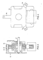
- Fig. 2 einen Schnitt entlang der Schnittlinie II-II in Fig. 1,
- Fig. 3 einen Schnitt entlang der Schnittlinie II-III-III in Fig. 1,
- Fig. 4 eine Draufsicht auf einen erfindungsgemäßen Motorflansch,
- Fig. 5 bis 8 Ansichten entlang der Schnittlinie III-III in Fig. 1 mit verschiedenen Ausführungsbeispielen für die Lagerung und die Befestigung des Statorblechpaketes,
- Fig. 9 einen Schnitt durch zwei alternative Ausführungen des erfindungsgemäßen Motors (obere Hälfte, untere Hälfte).
- In Fig. 1 ist ein erfindungsgemäße asymmetrischer Spaltpolmotor 1 dargestellt. Dieser Spaltpolmotor besteht aus einem Dynamoblechpaket als Stator 2 und einem Rotor 3. Die in Fig. 1 dargestellte Ansicht zeigt den erfindungsgemäßen Spaltpolmotor 1 von der Motorflanschseite aus gesehen. Der Rotor 3 ist ebenfalls aus einem aus einzlnen Blechlamellen geschichteten Blechpaket hergestellt. Der Stator 2 und der Rotor 3 sind aufgrund der erfindungsgemäßen Ausbildung des Spaltpolmotors 1 im sogenannten Stanzpaktierverfahren hergestellt. Der Stator ist C-förmig ausgebildet, und sein Jochsteg 4 ist als separates Teil ausgebildet, so daß es herausnehmbar ist. Hierdurch ergibt sich die Möglichkeit einer rationellen Fertigung von einer auf dem Joch aufgebrachten Erregerspule 5 (Hauptwicklung). Denn die Erregerspule 5 kann auf einen Spulenkörper im herausgenommenen Zustand des Jochsteges gewickelt werden, und zwar auf einen auf das Joch aufgeschobenen Spulenkörper 6. Nach dem Bewickeln des Jochsteges 4 mit der Erregerwicklung kann dann der Jochsteg 4 zwischen den beiden Jochzangen 7 und 8 des Stators 2 durch Einpressen befestigt werden. Weiterhin weist der Stator 2 Hilfswicklungen 9 auf, die beispielsweise aus blanken, kurzgeschlossenen Kupferwicklungen bestehen. Die Hilfswicklungen 9 sind einander diagonal gegnüberliegend am Umfang der den Rotor 3 aufnehmenden Öffnung 10 im Stator 2 ausgebildet. Im Stator 2 sind vorzugsweise vier Bohrungen 11 ausgebildet, die in den Ecken eines Viereckes, insbesondere Quadrats, angeordnet sind, durch dessen Mittelpunkt die Drehachse des Rotors 3 verläuft.
- Wie sich aus Fig. 2 ergibt, ist der Motorflansch 12, der zur Befestigung des Motors dient, mit einem Lagertragrohr 13 versehen, wobei das Lagertragrohr 13 vorzugsweise einstückig mit dem Motorflansch 12 ist. Dieses Lagertragrohr 13 verläuft koaxial zum Rotor 3, der das Lagertragrohr 13 umschließt und vorzugsweise vollständig aufnimmt. Erfindungsgemäß ist der Rotor 3 becherförmig ausgebildet, so daß das Lagertragrohr 13 von der offenen Seite des Rotors 3 her in diesen hineinragt. In dem Lagertragrohr 13 sind Lagerkörper 14 angeordnet, und zwar vorzugsweise jeweils in den beiden Endbereichen des Lagertragrohres 13. Diese Lagerkörper 14 können aus Kugellagern, Gleitlagern oder aus einer Kombination von beiden bestehen. Aufgrund der einstückigen Ausführung von Motorflansch 12 und Lagertragrohr 13 können die Lagersitze für die Lagerkörper 14 derart von innen bearbeitet werden, daß Fluchtungsfehler zwischen den beiden Lagerkörpern praktisch ausgeschlossen sind. Hierzu wird das am Motorflansch 12 befestigte Lagertragrohr 13 an seiner Außenseite eingespannt und an seiner Innenseite beidseitig gleichzeitig bearbeitet.
- Der hohlzylindrische Rotor 3 weist an dem dem Lagertragrohr gegenüberliegenden Ende einen Boden 15 mit einer Buchse 16 auf, über die der Rotor 3 mit einer Welle 17 kraftschlüssig verbunden ist. Wie bereits ausgeführt, besteht der Rotor 3 aus einzelnen aufeinandergeschichteten Blechlamellen. Diese sind bei dem erfindungsgemäßen Motor, wie an sich bekannt, durch eine Kurzschlußwicklung, die aus Aluminium bzw. einer Aluminiumlegierung besteht, miteinander und mit stirnseitigen Kurzschlußringen verbunden. Der Boden 15 des Rotors 3 ist vorzugsweise vollständig geschlossen und kann dabei an seiner Außenseite Kühlrippen aufweisen. Alternativ kann er auch aus radialen Stegen gebildet werdne, zwischen denen der Rotorboden zur besseren Kühlung der Lagerelemente Öffnungen aufweist. Wie in der Fig. 2 dargestellt, kann bei besonders hohen thermischen Belastungen auch ein zusätzliches Kühlrad 20 auf der Welle 17 außerhalb des erfindungsgemäßen Motors angeordnet sein. Die Welle 17 ist in bekannter Weise im Innern des Lagertragrohres 13 gelagert. Auf dem verlängerten, der Außenseite des Bodens 15 zugewandten Wellenende kann ein Lüfterrad, z. B. für eine Heißluftumwälzung, befestigt werden.
- Durch den erfindungsgemäßen Aufbau des Motors 1 mit der Unterbringung des Lagerung innerhalb des Rotors 3 ergibt sich aufgrund der radialen Vergrößerung des Rotors sowie der damit verbundenen Massezunahme eine ausgezeichnete Wärmeableitung über den Rotor nach außen. Eine thermische Belastung der Lagerelemente wird hierbei weitgehend vermieden. Außerdem wird durch diese erfindungsgemäße Bauform eine Erhöhung des Massenträgheitsmomentes erreicht, was bei ausgewuchteten Motoren für eine große Laufruhe des Motors sorgt. Zudem wirken sich eventuell vorhandene Restunwuchten, z. B. eines auf der Welle aufgesetzten Lüfterrades 33, infolge des vergrößerten Massenträgheitsmomentes des Rotors nur in vermindertem Maße auf die Laufruhe des Motors aus. Zum Auswuchten des Rotors können an dessen beiden Stirnseiten in Umfangsrichtung gleichmäßig verteilte Bohrungen vorgesehen sein.
- Wie sich aus Fig. 3 ergibt, wird der Stator 2 mittels Zapfen 21 am Motorflansch 12 befestigt. Diese Zapfen 21 verlaufen durch die Bohrungen 11 des Stators 2, wobei das den Stator 2 bildende Blechpaket bis zu einem Anschlag 22, der an den Zapfen 21 ausgebildet ist, aufgeschoben ist. Wie sich weiter aus Fig. 3 ergibt, wird das Ende der Zapfen 21 nach dem Aufschieben des Statorblechpaketes aufgebördelt, so daß ein Bördelrand 23 entsteht, durch den das Statorblechpaket zusammengehalten wird. Aufgrund dieser erfindungsgemäßen Befestigungsart des Statorblechpaketes ist es möglich, dieses nach dem Stanzpaketierverfahren vorzufertigen. Eine zusätzliche Maßnahme wie z. B. Verschweißen, Verschruaben oder dergleichen, um die einzelnen Blechlamellen des Statorblechpaketes zusammenzuhalten, ist nicht erforderlich.
- In den Fig. 5 bis 8 sind weitere Varianten für die Befestigung des Statorblechpaketes dargestellt.
- In Fig. 5 ist eine Befestigung des den Stator 2 bildenden Blechpaketes mittels Gewindeschrauben 24 gezeigt, wobei die Gewindeschrauben 24 in Hohlzylinderansätze 25 des Motorflansches 12 eingeschraubt werden, die ein entsprechendes Innengewinde aufweisen. Die Zylinderansätze 25 sind zur Zentrierung und als Montagehilfe für das Blechpaket des Stators an ihren freien Enden mit einem umlaufenden Absatz 26 versehen, der in die im Statorblechpaket befindliche Bohrung hineinragt. Die Lagerkörper 14 können beispielsweise als Gleitlager ausgebildet sein.
- In Fig. 6 ist eine Befestigung des Statorblechpaketes mit Hilfe von Hohlnieten 27 gezeigt. Diese Hohlniete werden in die freien Enden der Zapfen 21 eingenietet. Diese Hohlniete 27 dienen wiederum zum Zusammenhalten des Statorblechpaketes sowie zu dessen Befestigung. Die Lagerkörper 14 können beispielsweise als Kalottenlager ausgebildet sein. Anstatt von Hohlnieten können auch Vollniete verwendet werden.
- In Fig. 7 ist eine Befestigung des Statorblechpaketes dargestellt, die aus einer Schraube 28 bessteht, die nur in ihrem vorderen Bereich ein Gewinde aufweist und im übrigen zylindrisch ausgebildet ist. Der zylindrische Bereich ist länger als die Höhe des Statorblechpaketes, so daß die Schraube 28 mit ihrem zylindrischen Bereich aus dem Statorblechpaket herausragt und der zylindrische Bereich noch von der Bohrung des Ansatzes 25 aufgenommen wird, weshalb der Ansatz 25 nur in seinem unteren Bereich ein Gewinde aufweist. Der Außendurchmesser des zylindrischen Bereichs der Schraube 28 ist nur geringfügig kleiner als der Innendurchmesser der Bohrungen 11 im Statorblechpaket. Durch diese erfindungsgemäße Ausbildung ergibt sich bereits beim Einschieben der schrauben 28 eine Zentrierung des Stators. Als Anschlag für das Statorblechpaket dient das Stirnende des Zylinderansatzes 25, so daß das Statorblechpaket zwischen dem Schraubekopf und diesem Stirnende eingespannt ist. Die Lagerung der Welle 17 kann aus einer Kombination aus Gleitlager, insbesondere Kalottenlager, und Kugellager bestehen. Hierbei wird auf dem dem Motorflansch 12 zugewandten Ende das Gleitlager und auf der gegenüberliegenden Seite das Kugellager angeordnet sein.
- In Fig. 8 ist ein weiteres Ausführungsbeispiel für die Befestigung des Statorblechpaketes gezeigt, und zwar mittels einer Gewindeschraube mit Mutter, wobei die Mutter innerhalb des Motorflansches angeordnet ist. Bei dieser Ausführungsform weist der Zylinderansatz 25 einen Zentrierungsabsatz 26 auf, der in die Bohrungen 11 des Statorblechpaketes eingreift. Zur Aufnahme der Gewindeschraube 29 weist der Zylinderansatz 25 eine durchgehende Bohrung auf. Die Lagerung der Welle erfolgt durch Kugellager. In Fig. 4 ist eine Ansicht eines erfindungsgemäßen Motors von der Seite des Motorflnasches 12 aus gezeigt. Das gezeigte Ausführungsbeispiel wird als Heißluftgebläse verwendet. Hierzu besitzt der Motorflansch 12 drei bogenförmige Befestigungsarme 34, die sich an einer Rückwand eines nicht dargestellten Gerätes abstützen. Der Motorflansch wird vorzugsweise aus Aluminiumdruckguß hergestellt, wenn eine erhöhte thermische Belastung z. B. bei der Verwendung für Heißluftgebläse vorliegt. Für andere Ausführungen ist auch die Herstellung aus geeigneten Kunststoffmaterialien möglich.
- In Fig. 9 sind zwei weitere Ausführungsvarianten eines erfindungsgemäßen Motors dargestellt. Hierbei entspricht in der oberen Hälfte der grundsätzliche Aufbau der Lagerung der Ausführungsform wie in Fig. 8 beschrieben. In dem dargestellten Ausführungsbeispiel ist eine Riemenscheibe 31 auf dem Rotor 3 befestigt. Mittels dieser Riemenscheibe kann der erfindungsgemäße Motor als Antriebsaggregat dienen. Die Riemenscheibe kann auch einstückig mit dem Rotor 3 ausgebildet sein.
- In Fig. 9, untere Hälfte, ist eine Variante gezeigt, wo an der Stirnseite des Rotors 3 eine Impulsgeberscheibe 32 befestigt ist. Die Lagerung in Fig. 9, untere Hälfte, entspricht grundsätzlich der Ausführungsform in Fig. 6.
- Die beiden dargestellten Varianten sind deshalb möglich, da erfindungsgemäß der Rotor auf der dem Motorflansch 12 abgekehrten Seite frei zugänglich ist und insofern für verschiedenste Antriebs-, Meß- und Anzeigezwecke verwendet werden kann. Auch liegt es im Rahmen der Erfindung, die Außenseite des Rotors mit einer Außenverzahnung zu versehen, so daß der Rotor teil eines Getriebeantriebes sein kann.
- Weiterhin liegt es im Rahmen der Erfindung, wenn die Motorwelle 17 auch über den Motorflansch 12 hinaus nach außen verlängert ist.
- In den Figuren 1 bis 9 sind gleiche Teile mit denselben Bezugsziffern versehen.
- Die vorliegende Erfindung ist nicht auf die beschriebenen Ausführungsbeispiele beschränkt, sondern umfaßt alle im Sinne der Erfindung gleichwirkenden Ausführungen. Gegenüber den bekannten asymmetrischen Spaltpolmotoren besitzt der erfindungsgemäße Motor bei gleicher Leistung zwar verlän gerte Schenkellängen bzw. Zangenlängen des lamellierten Stators, jedoch ergibt sich eine wesentlich reduzierte Dicke des Eisenpaketes, so daß damit eine sehr flache Bauweise erreicht wird. Dies basiert auf der Erkenntnis, daß der erfindungsgemäße Motor keine Erhöhung des Eisenvolumens gegenüber leistungsgleichen, bekannten asymmetrischen Spaltmotoren erfordert, obwohl der erfindungsgemäß vorgesehene Rotor gegenüber den Rotoren leistungsgleicher, bekannter Spaltpolmotoren durchmesservergrößert ist.
Claims (11)
Priority Applications (1)
| Application Number | Priority Date | Filing Date | Title |
|---|---|---|---|
| AT87103420T ATE58264T1 (de) | 1986-05-28 | 1987-03-10 | Asymmetrischer spaltpolmotor. |
Applications Claiming Priority (2)
| Application Number | Priority Date | Filing Date | Title |
|---|---|---|---|
| DE19863617989 DE3617989A1 (de) | 1986-05-28 | 1986-05-28 | Asymmetrischer elektromotor |
| DE3617989 | 1986-05-28 |
Publications (3)
| Publication Number | Publication Date |
|---|---|
| EP0247301A2 true EP0247301A2 (de) | 1987-12-02 |
| EP0247301A3 EP0247301A3 (en) | 1988-10-12 |
| EP0247301B1 EP0247301B1 (de) | 1990-11-07 |
Family
ID=6301815
Family Applications (1)
| Application Number | Title | Priority Date | Filing Date |
|---|---|---|---|
| EP87103420A Expired - Lifetime EP0247301B1 (de) | 1986-05-28 | 1987-03-10 | Asymmetrischer Spaltpolmotor |
Country Status (5)
| Country | Link |
|---|---|
| US (1) | US4795931A (de) |
| EP (1) | EP0247301B1 (de) |
| AT (1) | ATE58264T1 (de) |
| DE (2) | DE3617989A1 (de) |
| ES (1) | ES2019074B3 (de) |
Cited By (3)
| Publication number | Priority date | Publication date | Assignee | Title |
|---|---|---|---|---|
| EP0620633A1 (de) * | 1993-04-13 | 1994-10-19 | Minebea Kabushiki-Kaisha | Motor |
| EP0664397A1 (de) * | 1994-01-24 | 1995-07-26 | JUWEL AQUARIUM GmbH & Co. KG | Impellerpumpe |
| EP3989414A1 (de) * | 2020-10-22 | 2022-04-27 | Cyltronic AG | Elektrozylinder, elektrozylinder mit einem magneten zur feststellung der position eines drehelements eines elektrozylinders sowie verwendung eines magneten zur positionsfeststellung eines drehelements |
Families Citing this family (12)
| Publication number | Priority date | Publication date | Assignee | Title |
|---|---|---|---|---|
| DE3906785A1 (de) * | 1989-03-03 | 1990-09-06 | Kugelfischer G Schaefer & Co | Waelzlagergehaeuse aus druckguss |
| US5365154A (en) * | 1991-07-12 | 1994-11-15 | North Coast Electronics, Inc. | Appliance control system and method |
| JP3069819B2 (ja) * | 1992-05-28 | 2000-07-24 | 富士通株式会社 | ヒートシンク並びに該ヒートシンクに用いるヒートシンク取付具及びヒートシンクを用いた可搬型電子装置 |
| US5783888A (en) * | 1994-03-17 | 1998-07-21 | Fuji Electric Co., Ltd. | Rotary electric machine |
| GB9525098D0 (en) * | 1995-12-08 | 1996-02-07 | Johnson Electric Sa | Electric motor |
| US5675206A (en) * | 1995-12-18 | 1997-10-07 | Siemens Electric Limited | Slim-line brushless motor |
| EP0903500B1 (de) * | 1997-09-19 | 2001-03-14 | TCG UNITECH Aktiengesellschaft | Elektrisch betriebene Kühlmittelpumpe |
| KR20050099352A (ko) * | 2004-04-09 | 2005-10-13 | 엘지전자 주식회사 | 전면 흡토출 방식의 공기조화기용 실외기 |
| US7420310B2 (en) * | 2004-11-26 | 2008-09-02 | Matsushita Electric Industries, Co., Ltd. | Brushless motor |
| CN101311548B (zh) * | 2007-05-25 | 2012-02-01 | 富准精密工业(深圳)有限公司 | 散热风扇 |
| DE102018212145A1 (de) | 2018-07-20 | 2020-01-23 | Brose Fahrzeugteile GmbH & Co. Kommanditgesellschaft, Würzburg | Elektromotor sowie Pumpe mit einem solchen Elektromotor |
| US11728700B2 (en) | 2020-02-05 | 2023-08-15 | Milwaukee Electric Tool Corporation | Electric motor for a power tool |
Family Cites Families (11)
| Publication number | Priority date | Publication date | Assignee | Title |
|---|---|---|---|---|
| US3513339A (en) * | 1966-12-07 | 1970-05-19 | Rotron Mfg Co | Electric motor construction |
| US4013910A (en) * | 1970-06-03 | 1977-03-22 | The Alliance Manufacturing Company, Inc. | Electric motor, stator and lamination therefor |
| US3626221A (en) * | 1970-09-14 | 1971-12-07 | Airtrol Corp | Electric motor with permanently lubricated bearings |
| DE2102679C2 (de) * | 1971-01-21 | 1982-12-30 | Papst-Motoren GmbH & Co KG, 7742 St Georgen | Elektro-Kleinmotor für einen Lüfter |
| DE2727920C3 (de) * | 1977-06-21 | 1987-01-22 | Wayne Jones Fort Wayne Ind. Morrill | Einlageriger Induktionskleinstmotor |
| US4219325A (en) * | 1978-07-10 | 1980-08-26 | Robinson Industries, Inc. | Axial flow reversible fan for a heat treating furnace |
| US4496869A (en) * | 1982-12-08 | 1985-01-29 | Tobishi Industries Ltd. | Small shaded-pole motor |
| US4482832A (en) * | 1983-03-31 | 1984-11-13 | Rival Manufacturing Company | Shaded pole motor lamination |
| DE3326543A1 (de) * | 1983-07-22 | 1985-01-31 | Mulfingen Elektrobau Ebm | Aussenlaeufermotor fuer eine ventilator |
| US4618791A (en) * | 1985-10-17 | 1986-10-21 | Morrill Giles W | Rotor assembly with die cast shaft extension coupling |
| US4688324A (en) * | 1986-11-07 | 1987-08-25 | Morrill Wayne J | Electric motor assembly |
-
1986
- 1986-05-28 DE DE19863617989 patent/DE3617989A1/de not_active Withdrawn
-
1987
- 1987-03-10 DE DE8787103420T patent/DE3766002D1/de not_active Expired - Lifetime
- 1987-03-10 ES ES87103420T patent/ES2019074B3/es not_active Expired - Lifetime
- 1987-03-10 AT AT87103420T patent/ATE58264T1/de not_active IP Right Cessation
- 1987-03-10 EP EP87103420A patent/EP0247301B1/de not_active Expired - Lifetime
- 1987-05-27 US US07/054,689 patent/US4795931A/en not_active Expired - Lifetime
Cited By (6)
| Publication number | Priority date | Publication date | Assignee | Title |
|---|---|---|---|---|
| EP0620633A1 (de) * | 1993-04-13 | 1994-10-19 | Minebea Kabushiki-Kaisha | Motor |
| EP0664397A1 (de) * | 1994-01-24 | 1995-07-26 | JUWEL AQUARIUM GmbH & Co. KG | Impellerpumpe |
| EP3989414A1 (de) * | 2020-10-22 | 2022-04-27 | Cyltronic AG | Elektrozylinder, elektrozylinder mit einem magneten zur feststellung der position eines drehelements eines elektrozylinders sowie verwendung eines magneten zur positionsfeststellung eines drehelements |
| WO2022084427A1 (de) * | 2020-10-22 | 2022-04-28 | Cyltronic Ag | Elektrozylinder, elektrozylinder mit einem magneten zur feststellung der position eines drehelements eines elektrozylinders sowie verwendung eines magneten zur positionsfeststellung eines drehelements |
| JP2023550205A (ja) * | 2020-10-22 | 2023-11-30 | シルトロニック・アクチェンゲゼルシャフト | 電動シリンダ、電動シリンダの回転要素の位置を決定するための磁石を有する電動シリンダ、および回転要素の位置を決定するための磁石の使用 |
| US12429119B2 (en) | 2020-10-22 | 2025-09-30 | Cyltronic Ag | Electric cylinder, electric cylinder having a magnet for determining the positon of a rotary element of an electric cylinder and use of a magnet for determining the position of a rotary element |
Also Published As
| Publication number | Publication date |
|---|---|
| US4795931A (en) | 1989-01-03 |
| DE3617989A1 (de) | 1987-12-03 |
| EP0247301B1 (de) | 1990-11-07 |
| DE3766002D1 (de) | 1990-12-13 |
| ES2019074B3 (es) | 1991-06-01 |
| ATE58264T1 (de) | 1990-11-15 |
| EP0247301A3 (en) | 1988-10-12 |
Similar Documents
| Publication | Publication Date | Title |
|---|---|---|
| EP0247301B1 (de) | Asymmetrischer Spaltpolmotor | |
| EP0160971B1 (de) | Lagerung für Antriebsmotor eines kleinstventilators | |
| DE3877909T2 (de) | Rotorauswuchtung. | |
| DE69014642T2 (de) | Läufer mit reduzierten ventilationsverlusten. | |
| CH638933A5 (de) | Kleinelektromotor. | |
| EP3205004A1 (de) | Käfigläufer für eine elektrische asynchronmaschine mit einen kurzschlussring stabilisierender stützscheibe | |
| EP1642375A1 (de) | Vorrichtung, insbesondere elektrische maschine, mit über einen presssitz miteinander verbundenen bauteilen | |
| EP1524751B1 (de) | Bürstenloser Elektromotor | |
| DE60102752T2 (de) | Spindelmotor für Plattenantrieb | |
| DE10230006A1 (de) | Asynchronmaschine | |
| WO1986005028A1 (fr) | Aimant annulaire pour freins moteurs | |
| DE2223858A1 (de) | Veränderliche Wirbelstromkupplung | |
| DE540080C (de) | Elektromotor mit das Staenderblechpaket umschliessenden Blechkappen | |
| EP0604646A1 (de) | Elektrische maschine | |
| AT525718B1 (de) | Rotor | |
| EP1513244A1 (de) | Aussenläufermotor | |
| DE9003390U1 (de) | Elektrische Synchronmaschine mit einem Schenkelpolläufer | |
| DE2059017A1 (de) | Elektromotor geringer Leistung | |
| DE2105738C3 (de) | Elektrischer Schrittmotor | |
| DE69501800T2 (de) | Verbesserungen an Kraftfahrzeuggetrieben mit Wirbelstrombremse und an den Getriebebefestigungsteilen | |
| DE8614442U1 (de) | Asymmetrischer Elektromotor | |
| DE102019214322A1 (de) | Stator eines Elektromotors | |
| DE1973001U (de) | Befestigung der stator-blechpakete im motorgehaeuse. | |
| DE2159640C3 (de) | Mehrphasiger elektrischer Schrittmotor | |
| DE4039571A1 (de) | Kollektorloser aussenlaeufermotor mit loesbar befestigten lagerschilden |
Legal Events
| Date | Code | Title | Description |
|---|---|---|---|
| PUAI | Public reference made under article 153(3) epc to a published international application that has entered the european phase |
Free format text: ORIGINAL CODE: 0009012 |
|
| AK | Designated contracting states |
Kind code of ref document: A2 Designated state(s): AT BE CH DE ES FR GB IT LI LU NL SE |
|
| 17P | Request for examination filed |
Effective date: 19871105 |
|
| PUAL | Search report despatched |
Free format text: ORIGINAL CODE: 0009013 |
|
| AK | Designated contracting states |
Kind code of ref document: A3 Designated state(s): AT BE CH DE ES FR GB IT LI LU NL SE |
|
| 17Q | First examination report despatched |
Effective date: 19881219 |
|
| GRAA | (expected) grant |
Free format text: ORIGINAL CODE: 0009210 |
|
| AK | Designated contracting states |
Kind code of ref document: B1 Designated state(s): AT BE CH DE ES FR GB IT LI LU NL SE |
|
| REF | Corresponds to: |
Ref document number: 58264 Country of ref document: AT Date of ref document: 19901115 Kind code of ref document: T |
|
| ITF | It: translation for a ep patent filed | ||
| REF | Corresponds to: |
Ref document number: 3766002 Country of ref document: DE Date of ref document: 19901213 |
|
| GBT | Gb: translation of ep patent filed (gb section 77(6)(a)/1977) | ||
| ET | Fr: translation filed | ||
| ITTA | It: last paid annual fee | ||
| PLBE | No opposition filed within time limit |
Free format text: ORIGINAL CODE: 0009261 |
|
| STAA | Information on the status of an ep patent application or granted ep patent |
Free format text: STATUS: NO OPPOSITION FILED WITHIN TIME LIMIT |
|
| 26N | No opposition filed | ||
| EPTA | Lu: last paid annual fee | ||
| EAL | Se: european patent in force in sweden |
Ref document number: 87103420.3 |
|
| PGFP | Annual fee paid to national office [announced via postgrant information from national office to epo] |
Ref country code: LU Payment date: 19950201 Year of fee payment: 10 |
|
| PGFP | Annual fee paid to national office [announced via postgrant information from national office to epo] |
Ref country code: AT Payment date: 19960329 Year of fee payment: 10 |
|
| PG25 | Lapsed in a contracting state [announced via postgrant information from national office to epo] |
Ref country code: LU Free format text: LAPSE BECAUSE OF NON-PAYMENT OF DUE FEES Effective date: 19970310 Ref country code: AT Effective date: 19970310 |
|
| PGFP | Annual fee paid to national office [announced via postgrant information from national office to epo] |
Ref country code: SE Payment date: 20000317 Year of fee payment: 14 |
|
| PGFP | Annual fee paid to national office [announced via postgrant information from national office to epo] |
Ref country code: NL Payment date: 20000331 Year of fee payment: 14 |
|
| PGFP | Annual fee paid to national office [announced via postgrant information from national office to epo] |
Ref country code: BE Payment date: 20000405 Year of fee payment: 14 |
|
| PG25 | Lapsed in a contracting state [announced via postgrant information from national office to epo] |
Ref country code: SE Free format text: LAPSE BECAUSE OF NON-PAYMENT OF DUE FEES Effective date: 20010311 |
|
| PG25 | Lapsed in a contracting state [announced via postgrant information from national office to epo] |
Ref country code: BE Free format text: LAPSE BECAUSE OF NON-PAYMENT OF DUE FEES Effective date: 20010331 |
|
| BERE | Be: lapsed |
Owner name: EBM ELEKTROBAU MULFINGEN G.M.B.H. & CO. Effective date: 20010331 |
|
| PG25 | Lapsed in a contracting state [announced via postgrant information from national office to epo] |
Ref country code: NL Free format text: LAPSE BECAUSE OF NON-PAYMENT OF DUE FEES Effective date: 20011001 |
|
| EUG | Se: european patent has lapsed |
Ref document number: 87103420.3 |
|
| NLV4 | Nl: lapsed or anulled due to non-payment of the annual fee |
Effective date: 20011001 |
|
| REG | Reference to a national code |
Ref country code: GB Ref legal event code: IF02 |
|
| PGFP | Annual fee paid to national office [announced via postgrant information from national office to epo] |
Ref country code: GB Payment date: 20020304 Year of fee payment: 16 |
|
| PGFP | Annual fee paid to national office [announced via postgrant information from national office to epo] |
Ref country code: ES Payment date: 20020308 Year of fee payment: 16 |
|
| PGFP | Annual fee paid to national office [announced via postgrant information from national office to epo] |
Ref country code: FR Payment date: 20020328 Year of fee payment: 16 |
|
| PGFP | Annual fee paid to national office [announced via postgrant information from national office to epo] |
Ref country code: CH Payment date: 20020607 Year of fee payment: 16 |
|
| PG25 | Lapsed in a contracting state [announced via postgrant information from national office to epo] |
Ref country code: GB Free format text: LAPSE BECAUSE OF NON-PAYMENT OF DUE FEES Effective date: 20030310 |
|
| PG25 | Lapsed in a contracting state [announced via postgrant information from national office to epo] |
Ref country code: ES Free format text: LAPSE BECAUSE OF NON-PAYMENT OF DUE FEES Effective date: 20030311 |
|
| PG25 | Lapsed in a contracting state [announced via postgrant information from national office to epo] |
Ref country code: LI Free format text: LAPSE BECAUSE OF NON-PAYMENT OF DUE FEES Effective date: 20030331 Ref country code: CH Free format text: LAPSE BECAUSE OF NON-PAYMENT OF DUE FEES Effective date: 20030331 |
|
| PGFP | Annual fee paid to national office [announced via postgrant information from national office to epo] |
Ref country code: DE Payment date: 20030527 Year of fee payment: 17 |
|
| GBPC | Gb: european patent ceased through non-payment of renewal fee |
Effective date: 20030310 |
|
| REG | Reference to a national code |
Ref country code: CH Ref legal event code: PL |
|
| PG25 | Lapsed in a contracting state [announced via postgrant information from national office to epo] |
Ref country code: FR Free format text: LAPSE BECAUSE OF NON-PAYMENT OF DUE FEES Effective date: 20031127 |
|
| REG | Reference to a national code |
Ref country code: FR Ref legal event code: ST |
|
| REG | Reference to a national code |
Ref country code: ES Ref legal event code: FD2A Effective date: 20030311 |
|
| PG25 | Lapsed in a contracting state [announced via postgrant information from national office to epo] |
Ref country code: DE Free format text: LAPSE BECAUSE OF NON-PAYMENT OF DUE FEES Effective date: 20041001 |
|
| PG25 | Lapsed in a contracting state [announced via postgrant information from national office to epo] |
Ref country code: IT Free format text: LAPSE BECAUSE OF NON-PAYMENT OF DUE FEES;WARNING: LAPSES OF ITALIAN PATENTS WITH EFFECTIVE DATE BEFORE 2007 MAY HAVE OCCURRED AT ANY TIME BEFORE 2007. THE CORRECT EFFECTIVE DATE MAY BE DIFFERENT FROM THE ONE RECORDED. Effective date: 20050310 |