EP0247301A2 - Moteur à pôles fendus asymétrique - Google Patents
Moteur à pôles fendus asymétrique Download PDFInfo
- Publication number
- EP0247301A2 EP0247301A2 EP87103420A EP87103420A EP0247301A2 EP 0247301 A2 EP0247301 A2 EP 0247301A2 EP 87103420 A EP87103420 A EP 87103420A EP 87103420 A EP87103420 A EP 87103420A EP 0247301 A2 EP0247301 A2 EP 0247301A2
- Authority
- EP
- European Patent Office
- Prior art keywords
- rotor
- stator
- shaded
- pole motor
- asymmetric
- Prior art date
- Legal status (The legal status is an assumption and is not a legal conclusion. Google has not performed a legal analysis and makes no representation as to the accuracy of the status listed.)
- Granted
Links
Images
Classifications
-
- H—ELECTRICITY
- H02—GENERATION; CONVERSION OR DISTRIBUTION OF ELECTRIC POWER
- H02K—DYNAMO-ELECTRIC MACHINES
- H02K5/00—Casings; Enclosures; Supports
- H02K5/04—Casings or enclosures characterised by the shape, form or construction thereof
- H02K5/16—Means for supporting bearings, e.g. insulating supports or means for fitting bearings in the bearing-shields
- H02K5/167—Means for supporting bearings, e.g. insulating supports or means for fitting bearings in the bearing-shields using sliding-contact or spherical cap bearings
- H02K5/1675—Means for supporting bearings, e.g. insulating supports or means for fitting bearings in the bearing-shields using sliding-contact or spherical cap bearings radially supporting the rotary shaft at only one end of the rotor
-
- H—ELECTRICITY
- H02—GENERATION; CONVERSION OR DISTRIBUTION OF ELECTRIC POWER
- H02K—DYNAMO-ELECTRIC MACHINES
- H02K1/00—Details of the magnetic circuit
- H02K1/06—Details of the magnetic circuit characterised by the shape, form or construction
- H02K1/12—Stationary parts of the magnetic circuit
- H02K1/18—Means for mounting or fastening magnetic stationary parts on to, or to, the stator structures
- H02K1/185—Means for mounting or fastening magnetic stationary parts on to, or to, the stator structures to outer stators
-
- H—ELECTRICITY
- H02—GENERATION; CONVERSION OR DISTRIBUTION OF ELECTRIC POWER
- H02K—DYNAMO-ELECTRIC MACHINES
- H02K17/00—Asynchronous induction motors; Asynchronous induction generators
- H02K17/02—Asynchronous induction motors
- H02K17/04—Asynchronous induction motors for single phase current
- H02K17/10—Motors with auxiliary phase obtained by split-pole carrying short-circuited windings
-
- H—ELECTRICITY
- H02—GENERATION; CONVERSION OR DISTRIBUTION OF ELECTRIC POWER
- H02K—DYNAMO-ELECTRIC MACHINES
- H02K17/00—Asynchronous induction motors; Asynchronous induction generators
- H02K17/02—Asynchronous induction motors
- H02K17/16—Asynchronous induction motors having rotors with internally short-circuited windings, e.g. cage rotors
-
- H—ELECTRICITY
- H02—GENERATION; CONVERSION OR DISTRIBUTION OF ELECTRIC POWER
- H02K—DYNAMO-ELECTRIC MACHINES
- H02K5/00—Casings; Enclosures; Supports
- H02K5/04—Casings or enclosures characterised by the shape, form or construction thereof
- H02K5/16—Means for supporting bearings, e.g. insulating supports or means for fitting bearings in the bearing-shields
- H02K5/173—Means for supporting bearings, e.g. insulating supports or means for fitting bearings in the bearing-shields using bearings with rolling contact, e.g. ball bearings
- H02K5/1735—Means for supporting bearings, e.g. insulating supports or means for fitting bearings in the bearing-shields using bearings with rolling contact, e.g. ball bearings radially supporting the rotary shaft at only one end of the rotor
Definitions
- the present invention relates to an asymmetrical shaded-pole motor with a stator made of a laminated laminated core formed from a C-shaped yoke, between whose free pliers legs a yoke web is pressed, on which a main winding is seated, and in the C-legs connecting the pliers legs, a short-circuited auxiliary winding and in one Recess of this leg a laminated squirrel-cage rotor with a small air gap to the stator are rotatably arranged on a motor shaft.
- Such a motor is already known from DE-OS 32 46 595.
- the shaft of the rotor is accommodated in a bore located in the center of the rotor laminated core.
- a bearing plate with integrated bearing elements which is screwed on both sides to the stator lamination stack, is used to fix the rotor attached to the shaft to the stator lamination stack.
- the present invention is based on the object, starting from an asymmetrical shaded-pole motor of the type described above, to improve it in such a way that a reliable mounting of the motor shaft without a curse tion error is given, as well as an improved heat dissipation from the storage area is achieved and unbalances caused by parts driven via the motor shaft can be better compensated for, so that the motor runs very smoothly.
- the object on which the present invention is based is to create a structurally simple, compact and inexpensive to produce motor construction, the same iron volume being present in the yoke with the same power as in the known shaded-pole motors.
- the squirrel-cage rotor is of hollow cylindrical design and directly coaxially surrounds a bearing support tube projecting into its interior from its open side and connected to the stator, in which the motor shaft is guided in bearings and at the end opposite the bearing support tube with the rotor connected is.
- a motor is therefore created which can be referred to as an intermediate rotor motor, since the rotor is arranged in a rotating manner between the bearing support tube of the stator and the stator laminated core.
- the invention is based on the surprising finding that, despite the rotor having an enlarged diameter compared to the rotors of the known asymmetrical split motors of the same power, the iron volume remains unchanged, and this even has the additional effect that the entire motor has a shorter overall length than motors of conventional design with the same performance. Because of the configuration according to the invention, it is possible for the motor flange to be received on the outer surface of the bearing support tube when machining the bearing bore and for the bearing seats on both sides, which are located in the interior of the bearing support tube, to be machined. As a result, a misalignment of the two bearings which affects the service life of the ball bearing is excluded. Also the Heat transfer from the shaft to the bearing elements is largely reduced according to the invention.
- a synchronous motor for use in electrical watches or the like, in which a permanent-magnetic rotor is rotatably arranged around a bearing shoulder of the stator, the stator itself being made of magnetizable material.
- This rotor is not suitable, for example, for driving hot air devices, since here the motor shaft on the rotor opposite end emerges from the stator, so that the bearing area is directly exposed to the influence of heat.
- the section receiving the bearings protrudes far from the stator on the side facing away from the rotor, so that the overall length increases and the bearing is not enclosed by the rotor, but lies outside the actual motor.
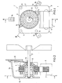
- FIG. 1 shows an asymmetrical shaded-pole motor 1 according to the invention.
- This shaded-pole motor consists of a dynamo sheet package as stator 2 and a rotor 3.
- the view shown in FIG. 1 shows the shaded-pole motor 1 according to the invention seen from the motor flange side.
- the rotor 3 is also made from a laminated core laminated from individual laminations.
- the stator 2 and the rotor 3 are manufactured based on the inventive design of the shaded-pole motor 1 in the so-called stamping compacting process.
- the stator is C-shaped and its yoke web 4 is designed as a separate part so that it can be removed. This results in the possibility of rational production of an excitation coil 5 (main winding) applied to the yoke.
- the stator has 2 auxiliary windings 9, which consist, for example, of bare, short-circuited copper windings.
- the auxiliary windings 9 are formed diagonally opposite one another on the circumference of the opening 3 accommodating the rotor 3 in the stator 2.
- Four bores 11 are preferably formed in the stator 2, which are arranged in the corners of a square, in particular a square, through the center of which the axis of rotation of the rotor 3 runs.
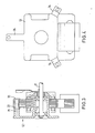
- the motor flange 12 which for Fastening of the motor is used, provided with a bearing support tube 13, wherein the bearing support tube 13 is preferably in one piece with the motor flange 12.
- This bearing support tube 13 runs coaxially to the rotor 3, which surrounds the bearing support tube 13 and preferably completely receives it.
- the rotor 3 is cup-shaped so that the bearing support tube 13 projects into the rotor 3 from the open side thereof.
- Bearing bodies 14 are arranged in the bearing support tube 13, preferably in each case in the two end regions of the bearing support tube 13. These bearing bodies 14 can consist of ball bearings, plain bearings or a combination of both.
- the bearing seats for the bearing body 14 can be machined from the inside in such a way that misalignments between the two bearing bodies are practically excluded.
- the bearing support tube 13 attached to the motor flange 12 is clamped on its outside and simultaneously machined on both sides of its inside.
- the hollow cylindrical rotor 3 has, at the end opposite the bearing support tube, a base 15 with a bushing 16, via which the rotor 3 is non-positively connected to a shaft 17.
- the rotor 3 consists of individual laminations laminated one on top of the other. In the motor according to the invention, as is known per se, these are connected to one another and to short-circuit rings at the end by a short-circuit winding which is made of aluminum or an aluminum alloy.
- the bottom 15 of the rotor 3 is preferably completely closed and can have cooling fins on its outside. Alternatively, it can also be formed from radial webs, between which the rotor base has openings for better cooling of the bearing elements. As shown in FIG.
- an additional cooling wheel can also be used in the case of particularly high thermal loads 20 can be arranged on the shaft 17 outside the motor according to the invention.
- the shaft 17 is mounted in a known manner inside the bearing support tube 13.
- the inventive construction of the motor 1 with the accommodation of the bearing within the rotor 3 results in excellent heat dissipation to the outside due to the radial enlargement of the rotor and the associated increase in mass. A thermal load on the bearing elements is largely avoided.
- an increase in the moment of inertia is achieved by this design according to the invention, which ensures a smooth running of the motor in balanced motors.
- any remaining unbalance, e.g. B. a mounted on the shaft fan 33 due to the increased mass moment of inertia of the rotor only to a reduced extent on the smooth running of the motor.
- evenly distributed bores can be provided in the circumferential direction on its two end faces.
- the stator 2 is fastened to the motor flange 12 by means of pins 21.
- These pins 21 run through the bores 11 of the stator 2, the laminated core forming the stator 2 being pushed up to a stop 22 which is formed on the pin 21.
- the end of the pins 21 is crimped after the stator laminated core has been pushed on, so that a flanged edge 23 is created by which the stator laminated core is held together. Due to this type of fastening of the stator laminated core according to the invention, it is possible to prefabricate it according to the punched packaging method. A additional measure such. B. welding, scrubbing or the like to hold the individual laminations of the stator laminated core together is not required.
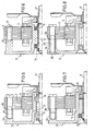
- 5 to 8 show further variants for fastening the stator laminated core.
- FIG. 5 shows a fastening of the laminated core forming the stator 2 by means of threaded screws 24, the threaded screws 24 being screwed into hollow cylinder lugs 25 of the motor flange 12 which have a corresponding internal thread.
- the cylinder lugs 25 are provided with a circumferential shoulder 26 at their free ends for centering and as an assembly aid for the laminated core of the stator, which protrudes into the bore in the stator laminated core.
- the bearing body 14 can for example be designed as a plain bearing.
- FIG. 6 shows a fastening of the stator laminated core using hollow rivets 27.
- These hollow rivets are riveted into the free ends of the pins 21.
- These hollow rivets 27 in turn serve to hold the stator laminated core together and to secure it.
- the bearing body 14 can for example be designed as a spherical bearing. Solid rivets can also be used instead of hollow rivets.
- FIG. 7 shows a fastening of the stator laminated core, which consists of a screw 28 which has a thread only in its front area and is otherwise cylindrical.
- the cylindrical region is longer than the height of the stator laminated core, so that the screw 28 projects with its cylindrical region from the stator laminated core and the cylindrical region is still received by the bore of the projection 25, which is why Approach 25 has a thread only in its lower region.
- the outside diameter of the cylindrical region of the screw 28 is only slightly smaller than the inside diameter of the bores 11 in the stator laminated core. This design according to the invention results in a centering of the stator when the screws 28 are inserted.
- the front end of the cylinder extension 25 serves as a stop for the stator laminated core, so that the stator laminated core is clamped between the screw head and this front end.
- the bearing of the shaft 17 can consist of a combination of plain bearings, in particular spherical bearings, and ball bearings. In this case, the slide bearing and the ball bearing will be arranged on the end facing the motor flange 12.
- FIG. 8 shows a further exemplary embodiment for fastening the stator laminated core, specifically by means of a threaded screw with a nut, the nut being arranged within the motor flange.
- the cylinder lug 25 has a centering shoulder 26 which engages in the bores 11 of the stator lamination stack.
- the cylinder extension 25 has a through hole.
- the shaft is supported by ball bearings.
- FIG. 4 shows a view of an engine according to the invention from the side of the engine bottle 12. The embodiment shown is used as a hot air blower.
- the motor flange 12 has three arc-shaped fastening arms 34 which are supported on a rear wall of a device, not shown.
- the motor flange is preferably made of die-cast aluminum when an increased thermal load z. B. when used for hot air blowers.
- the production from suitable plastic materials is also possible.
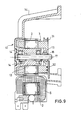
- FIG. 9 shows two further embodiment variants of an engine according to the invention.
- the basic structure of the mounting corresponds to the embodiment as described in FIG. 8.
- a pulley 31 is attached to the rotor 3.
- the motor according to the invention can serve as a drive unit.
- the pulley can also be formed in one piece with the rotor 3.
- FIG. 9 lower half, a variant is shown where a pulse generator disk 32 is attached to the end face of the rotor 3.
- the bottom half of FIG. 9 basically corresponds to the embodiment in FIG. 6.
- the rotor is freely accessible on the side facing away from the motor flange 12 and can therefore be used for a wide variety of drive, measurement and display purposes. It is also within the scope of the invention to provide the outside of the rotor with external teeth so that the rotor can be part of a gear drive.
- the present invention is not limited to the exemplary embodiments described, but encompasses all the embodiments having the same effect in the sense of the invention.
- the motor according to the invention has an extended output with the same power short leg lengths or pliers lengths of the laminated stator, but there is a significantly reduced thickness of the iron package, so that a very flat design is achieved. This is based on the knowledge that the motor according to the invention does not require an increase in the iron volume compared to known asymmetrical split motors of the same power, although the rotor provided according to the invention is enlarged in diameter compared to the rotors of known split pole motors of the same power.
Landscapes
- Engineering & Computer Science (AREA)
- Power Engineering (AREA)
- Iron Core Of Rotating Electric Machines (AREA)
- Motor Or Generator Frames (AREA)
- Fittings On The Vehicle Exterior For Carrying Loads, And Devices For Holding Or Mounting Articles (AREA)
- Dc Machiner (AREA)
Priority Applications (1)
| Application Number | Priority Date | Filing Date | Title |
|---|---|---|---|
| AT87103420T ATE58264T1 (de) | 1986-05-28 | 1987-03-10 | Asymmetrischer spaltpolmotor. |
Applications Claiming Priority (2)
| Application Number | Priority Date | Filing Date | Title |
|---|---|---|---|
| DE3617989 | 1986-05-28 | ||
| DE19863617989 DE3617989A1 (de) | 1986-05-28 | 1986-05-28 | Asymmetrischer elektromotor |
Publications (3)
| Publication Number | Publication Date |
|---|---|
| EP0247301A2 true EP0247301A2 (fr) | 1987-12-02 |
| EP0247301A3 EP0247301A3 (en) | 1988-10-12 |
| EP0247301B1 EP0247301B1 (fr) | 1990-11-07 |
Family
ID=6301815
Family Applications (1)
| Application Number | Title | Priority Date | Filing Date |
|---|---|---|---|
| EP87103420A Expired - Lifetime EP0247301B1 (fr) | 1986-05-28 | 1987-03-10 | Moteur à pôles fendus asymétrique |
Country Status (5)
| Country | Link |
|---|---|
| US (1) | US4795931A (fr) |
| EP (1) | EP0247301B1 (fr) |
| AT (1) | ATE58264T1 (fr) |
| DE (2) | DE3617989A1 (fr) |
| ES (1) | ES2019074B3 (fr) |
Cited By (3)
| Publication number | Priority date | Publication date | Assignee | Title |
|---|---|---|---|---|
| EP0620633A1 (fr) * | 1993-04-13 | 1994-10-19 | Minebea Kabushiki-Kaisha | Moteur |
| EP0664397A1 (fr) * | 1994-01-24 | 1995-07-26 | JUWEL AQUARIUM GmbH & Co. KG | Pompe à rouet |
| EP3989414A1 (fr) * | 2020-10-22 | 2022-04-27 | Cyltronic AG | Électrocylindre, électrocylindre doté d'un aimant permettant de déterminer la position d'un élément rotatif d'un électrocylindre ainsi qu'utilisation d'un aimant pour déterminer la position d'un élément rotatif |
Families Citing this family (12)
| Publication number | Priority date | Publication date | Assignee | Title |
|---|---|---|---|---|
| DE3906785A1 (de) * | 1989-03-03 | 1990-09-06 | Kugelfischer G Schaefer & Co | Waelzlagergehaeuse aus druckguss |
| US5365154A (en) * | 1991-07-12 | 1994-11-15 | North Coast Electronics, Inc. | Appliance control system and method |
| JP3069819B2 (ja) * | 1992-05-28 | 2000-07-24 | 富士通株式会社 | ヒートシンク並びに該ヒートシンクに用いるヒートシンク取付具及びヒートシンクを用いた可搬型電子装置 |
| US5783888A (en) * | 1994-03-17 | 1998-07-21 | Fuji Electric Co., Ltd. | Rotary electric machine |
| GB9525098D0 (en) * | 1995-12-08 | 1996-02-07 | Johnson Electric Sa | Electric motor |
| US5675206A (en) * | 1995-12-18 | 1997-10-07 | Siemens Electric Limited | Slim-line brushless motor |
| ES2155717T3 (es) * | 1997-09-19 | 2001-05-16 | Tcg Unitech Ag | Boma de refrigerante accionada electricamente. |
| KR20050099352A (ko) * | 2004-04-09 | 2005-10-13 | 엘지전자 주식회사 | 전면 흡토출 방식의 공기조화기용 실외기 |
| US7420310B2 (en) * | 2004-11-26 | 2008-09-02 | Matsushita Electric Industries, Co., Ltd. | Brushless motor |
| CN101311548B (zh) * | 2007-05-25 | 2012-02-01 | 富准精密工业(深圳)有限公司 | 散热风扇 |
| DE102018212145A1 (de) | 2018-07-20 | 2020-01-23 | Brose Fahrzeugteile GmbH & Co. Kommanditgesellschaft, Würzburg | Elektromotor sowie Pumpe mit einem solchen Elektromotor |
| CN220022577U (zh) | 2020-02-05 | 2023-11-14 | 米沃奇电动工具公司 | 动力工具及电动马达组件 |
Family Cites Families (11)
| Publication number | Priority date | Publication date | Assignee | Title |
|---|---|---|---|---|
| US3513339A (en) * | 1966-12-07 | 1970-05-19 | Rotron Mfg Co | Electric motor construction |
| US4013910A (en) * | 1970-06-03 | 1977-03-22 | The Alliance Manufacturing Company, Inc. | Electric motor, stator and lamination therefor |
| US3626221A (en) * | 1970-09-14 | 1971-12-07 | Airtrol Corp | Electric motor with permanently lubricated bearings |
| DE2102679C2 (de) * | 1971-01-21 | 1982-12-30 | Papst-Motoren GmbH & Co KG, 7742 St Georgen | Elektro-Kleinmotor für einen Lüfter |
| DE2727920C3 (de) * | 1977-06-21 | 1987-01-22 | Wayne Jones Fort Wayne Ind. Morrill | Einlageriger Induktionskleinstmotor |
| US4219325A (en) * | 1978-07-10 | 1980-08-26 | Robinson Industries, Inc. | Axial flow reversible fan for a heat treating furnace |
| US4496869A (en) * | 1982-12-08 | 1985-01-29 | Tobishi Industries Ltd. | Small shaded-pole motor |
| US4482832A (en) * | 1983-03-31 | 1984-11-13 | Rival Manufacturing Company | Shaded pole motor lamination |
| DE3326543A1 (de) * | 1983-07-22 | 1985-01-31 | Mulfingen Elektrobau Ebm | Aussenlaeufermotor fuer eine ventilator |
| US4618791A (en) * | 1985-10-17 | 1986-10-21 | Morrill Giles W | Rotor assembly with die cast shaft extension coupling |
| US4688324A (en) * | 1986-11-07 | 1987-08-25 | Morrill Wayne J | Electric motor assembly |
-
1986
- 1986-05-28 DE DE19863617989 patent/DE3617989A1/de not_active Withdrawn
-
1987
- 1987-03-10 AT AT87103420T patent/ATE58264T1/de not_active IP Right Cessation
- 1987-03-10 DE DE8787103420T patent/DE3766002D1/de not_active Expired - Lifetime
- 1987-03-10 EP EP87103420A patent/EP0247301B1/fr not_active Expired - Lifetime
- 1987-03-10 ES ES87103420T patent/ES2019074B3/es not_active Expired - Lifetime
- 1987-05-27 US US07/054,689 patent/US4795931A/en not_active Expired - Lifetime
Cited By (6)
| Publication number | Priority date | Publication date | Assignee | Title |
|---|---|---|---|---|
| EP0620633A1 (fr) * | 1993-04-13 | 1994-10-19 | Minebea Kabushiki-Kaisha | Moteur |
| EP0664397A1 (fr) * | 1994-01-24 | 1995-07-26 | JUWEL AQUARIUM GmbH & Co. KG | Pompe à rouet |
| EP3989414A1 (fr) * | 2020-10-22 | 2022-04-27 | Cyltronic AG | Électrocylindre, électrocylindre doté d'un aimant permettant de déterminer la position d'un élément rotatif d'un électrocylindre ainsi qu'utilisation d'un aimant pour déterminer la position d'un élément rotatif |
| WO2022084427A1 (fr) * | 2020-10-22 | 2022-04-28 | Cyltronic Ag | Cylindre électrique, cylindre électrique doté d'un aimant pour déterminer la position d'un élément rotatif d'un cylindre électrique et utilisation d'un aimant pour déterminer la position d'un élément rotatif |
| JP2023550205A (ja) * | 2020-10-22 | 2023-11-30 | シルトロニック・アクチェンゲゼルシャフト | 電動シリンダ、電動シリンダの回転要素の位置を決定するための磁石を有する電動シリンダ、および回転要素の位置を決定するための磁石の使用 |
| US12429119B2 (en) | 2020-10-22 | 2025-09-30 | Cyltronic Ag | Electric cylinder, electric cylinder having a magnet for determining the positon of a rotary element of an electric cylinder and use of a magnet for determining the position of a rotary element |
Also Published As
| Publication number | Publication date |
|---|---|
| DE3766002D1 (de) | 1990-12-13 |
| ATE58264T1 (de) | 1990-11-15 |
| ES2019074B3 (es) | 1991-06-01 |
| EP0247301B1 (fr) | 1990-11-07 |
| US4795931A (en) | 1989-01-03 |
| DE3617989A1 (de) | 1987-12-03 |
| EP0247301A3 (en) | 1988-10-12 |
Similar Documents
| Publication | Publication Date | Title |
|---|---|---|
| EP0247301B1 (fr) | Moteur à pôles fendus asymétrique | |
| EP0160971B1 (fr) | Placement des paliers pour un moteur actionnant un micro-ventilateur | |
| DE3877909T2 (de) | Rotorauswuchtung. | |
| DE102012215503A1 (de) | Rotor einer elektrischen Maschine und elektrische Maschine | |
| CH638933A5 (de) | Kleinelektromotor. | |
| EP3205004A1 (fr) | Rotor à cage destiné à un moteur électrique asynchrone, muni d'un disque de support stabilisant la bague de court-circuit | |
| EP1642375A1 (fr) | Dispositif, notamment machine electrique, comportant des elements constitutifs raccordes mutuellement par l'intermediaire d'un ajustement serre | |
| EP1524751B1 (fr) | Moteur électrique sans balai | |
| DE60102752T2 (de) | Spindelmotor für Plattenantrieb | |
| DE705239C (de) | Induktionsmotor | |
| DE10230006A1 (de) | Asynchronmaschine | |
| WO1986005028A1 (fr) | Aimant annulaire pour freins moteurs | |
| DE2223858A1 (de) | Veränderliche Wirbelstromkupplung | |
| DE540080C (de) | Elektromotor mit das Staenderblechpaket umschliessenden Blechkappen | |
| EP0604646A1 (fr) | Machine electrique | |
| AT525718B1 (de) | Rotor | |
| DE9003390U1 (de) | Elektrische Synchronmaschine mit einem Schenkelpolläufer | |
| DE2059017A1 (de) | Elektromotor geringer Leistung | |
| DE2105738C3 (de) | Elektrischer Schrittmotor | |
| DE69501800T2 (de) | Verbesserungen an Kraftfahrzeuggetrieben mit Wirbelstrombremse und an den Getriebebefestigungsteilen | |
| DE8614442U1 (de) | Asymmetrischer Elektromotor | |
| DE102019214322A1 (de) | Stator eines Elektromotors | |
| DE1973001U (de) | Befestigung der stator-blechpakete im motorgehaeuse. | |
| DE3645262C2 (de) | Induktionsmotor | |
| DE2159640C3 (de) | Mehrphasiger elektrischer Schrittmotor |
Legal Events
| Date | Code | Title | Description |
|---|---|---|---|
| PUAI | Public reference made under article 153(3) epc to a published international application that has entered the european phase |
Free format text: ORIGINAL CODE: 0009012 |
|
| AK | Designated contracting states |
Kind code of ref document: A2 Designated state(s): AT BE CH DE ES FR GB IT LI LU NL SE |
|
| 17P | Request for examination filed |
Effective date: 19871105 |
|
| PUAL | Search report despatched |
Free format text: ORIGINAL CODE: 0009013 |
|
| AK | Designated contracting states |
Kind code of ref document: A3 Designated state(s): AT BE CH DE ES FR GB IT LI LU NL SE |
|
| 17Q | First examination report despatched |
Effective date: 19881219 |
|
| GRAA | (expected) grant |
Free format text: ORIGINAL CODE: 0009210 |
|
| AK | Designated contracting states |
Kind code of ref document: B1 Designated state(s): AT BE CH DE ES FR GB IT LI LU NL SE |
|
| REF | Corresponds to: |
Ref document number: 58264 Country of ref document: AT Date of ref document: 19901115 Kind code of ref document: T |
|
| ITF | It: translation for a ep patent filed | ||
| REF | Corresponds to: |
Ref document number: 3766002 Country of ref document: DE Date of ref document: 19901213 |
|
| GBT | Gb: translation of ep patent filed (gb section 77(6)(a)/1977) | ||
| ET | Fr: translation filed | ||
| ITTA | It: last paid annual fee | ||
| PLBE | No opposition filed within time limit |
Free format text: ORIGINAL CODE: 0009261 |
|
| STAA | Information on the status of an ep patent application or granted ep patent |
Free format text: STATUS: NO OPPOSITION FILED WITHIN TIME LIMIT |
|
| 26N | No opposition filed | ||
| EPTA | Lu: last paid annual fee | ||
| EAL | Se: european patent in force in sweden |
Ref document number: 87103420.3 |
|
| PGFP | Annual fee paid to national office [announced via postgrant information from national office to epo] |
Ref country code: LU Payment date: 19950201 Year of fee payment: 10 |
|
| PGFP | Annual fee paid to national office [announced via postgrant information from national office to epo] |
Ref country code: AT Payment date: 19960329 Year of fee payment: 10 |
|
| PG25 | Lapsed in a contracting state [announced via postgrant information from national office to epo] |
Ref country code: LU Free format text: LAPSE BECAUSE OF NON-PAYMENT OF DUE FEES Effective date: 19970310 Ref country code: AT Effective date: 19970310 |
|
| PGFP | Annual fee paid to national office [announced via postgrant information from national office to epo] |
Ref country code: SE Payment date: 20000317 Year of fee payment: 14 |
|
| PGFP | Annual fee paid to national office [announced via postgrant information from national office to epo] |
Ref country code: NL Payment date: 20000331 Year of fee payment: 14 |
|
| PGFP | Annual fee paid to national office [announced via postgrant information from national office to epo] |
Ref country code: BE Payment date: 20000405 Year of fee payment: 14 |
|
| PG25 | Lapsed in a contracting state [announced via postgrant information from national office to epo] |
Ref country code: SE Free format text: LAPSE BECAUSE OF NON-PAYMENT OF DUE FEES Effective date: 20010311 |
|
| PG25 | Lapsed in a contracting state [announced via postgrant information from national office to epo] |
Ref country code: BE Free format text: LAPSE BECAUSE OF NON-PAYMENT OF DUE FEES Effective date: 20010331 |
|
| BERE | Be: lapsed |
Owner name: EBM ELEKTROBAU MULFINGEN G.M.B.H. & CO. Effective date: 20010331 |
|
| PG25 | Lapsed in a contracting state [announced via postgrant information from national office to epo] |
Ref country code: NL Free format text: LAPSE BECAUSE OF NON-PAYMENT OF DUE FEES Effective date: 20011001 |
|
| EUG | Se: european patent has lapsed |
Ref document number: 87103420.3 |
|
| NLV4 | Nl: lapsed or anulled due to non-payment of the annual fee |
Effective date: 20011001 |
|
| REG | Reference to a national code |
Ref country code: GB Ref legal event code: IF02 |
|
| PGFP | Annual fee paid to national office [announced via postgrant information from national office to epo] |
Ref country code: GB Payment date: 20020304 Year of fee payment: 16 |
|
| PGFP | Annual fee paid to national office [announced via postgrant information from national office to epo] |
Ref country code: ES Payment date: 20020308 Year of fee payment: 16 |
|
| PGFP | Annual fee paid to national office [announced via postgrant information from national office to epo] |
Ref country code: FR Payment date: 20020328 Year of fee payment: 16 |
|
| PGFP | Annual fee paid to national office [announced via postgrant information from national office to epo] |
Ref country code: CH Payment date: 20020607 Year of fee payment: 16 |
|
| PG25 | Lapsed in a contracting state [announced via postgrant information from national office to epo] |
Ref country code: GB Free format text: LAPSE BECAUSE OF NON-PAYMENT OF DUE FEES Effective date: 20030310 |
|
| PG25 | Lapsed in a contracting state [announced via postgrant information from national office to epo] |
Ref country code: ES Free format text: LAPSE BECAUSE OF NON-PAYMENT OF DUE FEES Effective date: 20030311 |
|
| PG25 | Lapsed in a contracting state [announced via postgrant information from national office to epo] |
Ref country code: LI Free format text: LAPSE BECAUSE OF NON-PAYMENT OF DUE FEES Effective date: 20030331 Ref country code: CH Free format text: LAPSE BECAUSE OF NON-PAYMENT OF DUE FEES Effective date: 20030331 |
|
| PGFP | Annual fee paid to national office [announced via postgrant information from national office to epo] |
Ref country code: DE Payment date: 20030527 Year of fee payment: 17 |
|
| GBPC | Gb: european patent ceased through non-payment of renewal fee |
Effective date: 20030310 |
|
| REG | Reference to a national code |
Ref country code: CH Ref legal event code: PL |
|
| PG25 | Lapsed in a contracting state [announced via postgrant information from national office to epo] |
Ref country code: FR Free format text: LAPSE BECAUSE OF NON-PAYMENT OF DUE FEES Effective date: 20031127 |
|
| REG | Reference to a national code |
Ref country code: FR Ref legal event code: ST |
|
| REG | Reference to a national code |
Ref country code: ES Ref legal event code: FD2A Effective date: 20030311 |
|
| PG25 | Lapsed in a contracting state [announced via postgrant information from national office to epo] |
Ref country code: DE Free format text: LAPSE BECAUSE OF NON-PAYMENT OF DUE FEES Effective date: 20041001 |
|
| PG25 | Lapsed in a contracting state [announced via postgrant information from national office to epo] |
Ref country code: IT Free format text: LAPSE BECAUSE OF NON-PAYMENT OF DUE FEES;WARNING: LAPSES OF ITALIAN PATENTS WITH EFFECTIVE DATE BEFORE 2007 MAY HAVE OCCURRED AT ANY TIME BEFORE 2007. THE CORRECT EFFECTIVE DATE MAY BE DIFFERENT FROM THE ONE RECORDED. Effective date: 20050310 |