EP0246565A2 - Broche d'une machine-outil - Google Patents
Broche d'une machine-outil Download PDFInfo
- Publication number
- EP0246565A2 EP0246565A2 EP87107027A EP87107027A EP0246565A2 EP 0246565 A2 EP0246565 A2 EP 0246565A2 EP 87107027 A EP87107027 A EP 87107027A EP 87107027 A EP87107027 A EP 87107027A EP 0246565 A2 EP0246565 A2 EP 0246565A2
- Authority
- EP
- European Patent Office
- Prior art keywords
- spindle
- tool
- clamping
- spindle according
- elements
- Prior art date
- Legal status (The legal status is an assumption and is not a legal conclusion. Google has not performed a legal analysis and makes no representation as to the accuracy of the status listed.)
- Granted
Links
Images
Classifications
-
- B—PERFORMING OPERATIONS; TRANSPORTING
- B23—MACHINE TOOLS; METAL-WORKING NOT OTHERWISE PROVIDED FOR
- B23B—TURNING; BORING
- B23B31/00—Chucks; Expansion mandrels; Adaptations thereof for remote control
- B23B31/02—Chucks
- B23B31/24—Chucks characterised by features relating primarily to remote control of the gripping means
- B23B31/28—Chucks characterised by features relating primarily to remote control of the gripping means using electric or magnetic means in the chuck
-
- B—PERFORMING OPERATIONS; TRANSPORTING
- B23—MACHINE TOOLS; METAL-WORKING NOT OTHERWISE PROVIDED FOR
- B23B—TURNING; BORING
- B23B31/00—Chucks; Expansion mandrels; Adaptations thereof for remote control
- B23B31/02—Chucks
- B23B31/24—Chucks characterised by features relating primarily to remote control of the gripping means
- B23B31/30—Chucks characterised by features relating primarily to remote control of the gripping means using fluid-pressure means in the chuck
- B23B31/302—Hydraulic equipment, e.g. pistons, valves, rotary joints
-
- B—PERFORMING OPERATIONS; TRANSPORTING
- B23—MACHINE TOOLS; METAL-WORKING NOT OTHERWISE PROVIDED FOR
- B23B—TURNING; BORING
- B23B2260/00—Details of constructional elements
- B23B2260/002—Accumulators
-
- B—PERFORMING OPERATIONS; TRANSPORTING
- B23—MACHINE TOOLS; METAL-WORKING NOT OTHERWISE PROVIDED FOR
- B23B—TURNING; BORING
- B23B2260/00—Details of constructional elements
- B23B2260/102—Magnetostrictive elements
-
- B—PERFORMING OPERATIONS; TRANSPORTING
- B23—MACHINE TOOLS; METAL-WORKING NOT OTHERWISE PROVIDED FOR
- B23B—TURNING; BORING
- B23B2260/00—Details of constructional elements
- B23B2260/108—Piezoelectric elements
-
- Y—GENERAL TAGGING OF NEW TECHNOLOGICAL DEVELOPMENTS; GENERAL TAGGING OF CROSS-SECTIONAL TECHNOLOGIES SPANNING OVER SEVERAL SECTIONS OF THE IPC; TECHNICAL SUBJECTS COVERED BY FORMER USPC CROSS-REFERENCE ART COLLECTIONS [XRACs] AND DIGESTS
- Y10—TECHNICAL SUBJECTS COVERED BY FORMER USPC
- Y10T—TECHNICAL SUBJECTS COVERED BY FORMER US CLASSIFICATION
- Y10T279/00—Chucks or sockets
- Y10T279/12—Chucks or sockets with fluid-pressure actuator
- Y10T279/1208—Chucks or sockets with fluid-pressure actuator with measuring, indicating or control means
-
- Y—GENERAL TAGGING OF NEW TECHNOLOGICAL DEVELOPMENTS; GENERAL TAGGING OF CROSS-SECTIONAL TECHNOLOGIES SPANNING OVER SEVERAL SECTIONS OF THE IPC; TECHNICAL SUBJECTS COVERED BY FORMER USPC CROSS-REFERENCE ART COLLECTIONS [XRACs] AND DIGESTS
- Y10—TECHNICAL SUBJECTS COVERED BY FORMER USPC
- Y10T—TECHNICAL SUBJECTS COVERED BY FORMER US CLASSIFICATION
- Y10T279/00—Chucks or sockets
- Y10T279/12—Chucks or sockets with fluid-pressure actuator
- Y10T279/1241—Socket type
- Y10T279/1249—Collet
-
- Y—GENERAL TAGGING OF NEW TECHNOLOGICAL DEVELOPMENTS; GENERAL TAGGING OF CROSS-SECTIONAL TECHNOLOGIES SPANNING OVER SEVERAL SECTIONS OF THE IPC; TECHNICAL SUBJECTS COVERED BY FORMER USPC CROSS-REFERENCE ART COLLECTIONS [XRACs] AND DIGESTS
- Y10—TECHNICAL SUBJECTS COVERED BY FORMER USPC
- Y10T—TECHNICAL SUBJECTS COVERED BY FORMER US CLASSIFICATION
- Y10T279/00—Chucks or sockets
- Y10T279/33—Member applies axial force component
-
- Y—GENERAL TAGGING OF NEW TECHNOLOGICAL DEVELOPMENTS; GENERAL TAGGING OF CROSS-SECTIONAL TECHNOLOGIES SPANNING OVER SEVERAL SECTIONS OF THE IPC; TECHNICAL SUBJECTS COVERED BY FORMER USPC CROSS-REFERENCE ART COLLECTIONS [XRACs] AND DIGESTS
- Y10—TECHNICAL SUBJECTS COVERED BY FORMER USPC
- Y10T—TECHNICAL SUBJECTS COVERED BY FORMER US CLASSIFICATION
- Y10T408/00—Cutting by use of rotating axially moving tool
- Y10T408/94—Tool-support
- Y10T408/95—Tool-support with tool-retaining means
-
- Y—GENERAL TAGGING OF NEW TECHNOLOGICAL DEVELOPMENTS; GENERAL TAGGING OF CROSS-SECTIONAL TECHNOLOGIES SPANNING OVER SEVERAL SECTIONS OF THE IPC; TECHNICAL SUBJECTS COVERED BY FORMER USPC CROSS-REFERENCE ART COLLECTIONS [XRACs] AND DIGESTS
- Y10—TECHNICAL SUBJECTS COVERED BY FORMER USPC
- Y10T—TECHNICAL SUBJECTS COVERED BY FORMER US CLASSIFICATION
- Y10T409/00—Gear cutting, milling, or planing
- Y10T409/30—Milling
- Y10T409/309352—Cutter spindle or spindle support
- Y10T409/309408—Cutter spindle or spindle support with cutter holder
- Y10T409/309464—Cutter spindle or spindle support with cutter holder and draw bar
Definitions
- the invention relates to a spindle of a machine tool, which is rotatably mounted about a longitudinal axis, with clamping means for clamping and unclamping a tool, with an energy store, which has a first charge state when the tool is not clamped and a second charge state when the tool is clamped to tighten the clamping means occupies, and with an actuating unit for reloading the energy store by means of an external force supplied via a connection.
- a tool clamping device for a machine tool is known, as is usually used for drilling or milling workpieces at speeds of up to a few hundred revolutions per minute.
- a rotatable spindle is provided which has a cone bore for receiving a corresponding cone of a tool.
- clamping means in the form of a collet with radially outwardly extending hooks and a spreading rod movable in the collet are provided.
- hooks engage in an associated undercut ring groove in a central bore of the tool cone, and by advancing the spreader rod, the hooks grip laterally outwards and positively into this ring groove, so that the tool cone can be drawn into the receptacle of the spindle.
- the clamping means run out into a sleeve which is supported against the spindle via a set of disc springs.
- a spatially fixed piston-cylinder unit can be acted upon from the side facing away from the spindle via a spatially fixed connection by means of a hydraulic fluid, and the piston of this unit is provided in order to advance the clamping means into the conical bore of the spindle receptacle and at the same time compress the disc spring package.
- the hydraulic fluid is drained from the piston-cylinder unit again by means of a suitably attached switching pin, so that the disc spring package can relax at least partially and with its relaxation movement the tool under high axial force the spindle holder moves in.
- the invention is based on the object of developing a spindle of the type mentioned in such a way that it can be used in high-speed machine tools with speeds of typically several tens of thousands of revolutions per minute.
- actuating unit and the connection are arranged in the rotating part of the spindle, that the spindle rotates at least 30,000 revolutions per minute and that the connection is a detachable connection.
- the object on which the invention is based is completely achieved by these measures, because the spindle, together with the actuating unit and connection, is now the integrated compact unit which can be set to the high speeds mentioned with drive means known per se, for example a turbine or an electromagnetic drive.
- drive means known per se for example a turbine or an electromagnetic drive.
- the auxiliary person for example a hydraulic or pneumatic fluid, an electric current or the like, is detachable by means of the plug-in or screw connection. fed, and it is when unclamping the energy storage, for example a spring accumulator, a magnetic accumulator, a pressure accumulator or the like.
- the compact spindle unit can be set to the desired high speeds. It is also of major advantage in the spindle according to the invention that the spindle can be equipped with a tool separately from the machine tool, because the energy store is loaded independently of the machine tool via the plug-in or screw connection and is partially unloaded again when the workpiece is inserted for clamping can.
- the actuating unit is a piston-cylinder unit, to which a fluid can be supplied via a plug connected to a pressure line and a pressure-tight socket arranged in the spindle.
- the piston is a differential piston with a first part of larger diameter and a second part of smaller diameter, which run in corresponding first and second sections of a stepped bore, if the first section is also connected to the connection, the second Section is connected to the energy store designed as a pressure accumulator and the first section is connected to the second section and the pressure accumulator via a valve.
- the valve is a check valve, which ensures the separation of the pressure accumulator from the larger surface of the differential piston in a simple manner.
- the check valve can have a valve member that closes under pretension, which can be lifted off a valve seat by means of an actuating pin arranged on a plug, in particular the check valve can be arranged in a channel that is aligned with an axis of the socket.
- the pressure accumulator is arranged in the differential piston.
- a particularly good effect is achieved if the pressure accumulator is arranged rotationally symmetrically and along the longitudinal axis of the spindle.
- the pressure accumulator can have a part of an annular space which contains a compressible medium and is separated from another part via an annular membrane.
- the actuating unit is a pack of electro- or magnetostrictive elements, in particular piezo elements, to which electrical energy can be supplied via an electrical connecting means arranged on the spindle.
- This measure has the advantage that the tool can be clamped in the spindle in a particularly simple manner, namely by supplying electrical energy, the electro- or magnetostrictive elements used, in particular piezo elements, also working without wear and in a version is available in which very high clamping forces can also be generated. Dosing the clamping force by suitably adjusting the supply voltage or the supply current is also possible in this way without problems.
- the electrical connection means is a sliding contact, which rotates over a circumference of the spindle.
- This measure has the advantage that the actuating unit can be “reloaded” even when the spindle is rotating if the voltage generated by the elements should have decreased, for example as a result of leakage current losses.
- the tool can be drawn into the spindle against a first axial stop by means of a pull rod and the elements are arranged between a second axial stop facing the tool and a flange of the pull rod facing away from the tool.
- This measure has the advantage that when the tool is pulled into the spindle by means of the pull rod, the expansion of the elements is used, so that the elements are loaded under pressure when the tool is clamped, a load that they can withstand for a longer period of time than a tensile load.
- the elements are designed as ring elements, the pull rod passes through the ring elements and the flange is designed as an axially rigid disc connected to the pull rod.
- an embodiment of the invention is preferred, which is characterized in that the elements guide the actuating unit in a first position for inserting the tool into the spindle from a zero position of the clamping path to a part of the clamping path, in a second Hold the position for clamping the tool in the spindle on the full clamping path and, in a third position, reset it to the zero position of the clamping path when clamping the tool out of the spindle.
- This measure has the advantage that the already partially “preloaded” position of the actuating unit at the moment when the tool is used, for example manually or by a gripper of a handling system, on the one hand still leaves a sufficient clamping path for the tool to be securely accommodated to hold the spindle, but on the other hand, an opposite way out of the spindle can be carried out for unclamping, namely by completely loosening the actuating unit, so that the tool can also be safely ejected and removed from the spindle.
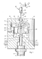
- FIG. 1 shows a spindle 10 holding a tool 8 and rotatable about a longitudinal axis 9 in a spindle holder 1 of a machine tool, not otherwise shown.
- the spindle 10 runs on its broken-off underside shown in a pull rod 11 which at the other end in a known manner, a collet, expansion elements with hooks or the like. carries in order to be able to pull the tool 8, for example a grinding wheel, into a corresponding receptacle of the spindle 10 and fix it there.
- the pull rod 11 ends in a differential piston 12, which has a first part 13 of a larger diameter, which runs in a first section 14 of a stepped bore. Below the first part 13 there is a second part 15 of the differential piston 1-2, which runs in a corresponding second section 16 of a stepped bore.
- a first cavity 19 is created during an axial movement of the differential piston 12 in the stepped bore above the first part 13, a second cavity 20 below the first part 13 and a third cavity 21 of the stepped bore below the second part 15.
- a vent hole 22 leads from the second cavity 20 to the outside.
- a bushing 26 with an O-ring 27 or another suitable sealing means is let into the upper side of the spindle 10, and the bushing 26 has a contour 28 which corresponds in mirror image to a contour 29 of a plug 30.
- a solenoid valve 32 is arranged in the pressure line 31, with which the pressure line 31 can optionally be connected to a line 33 leading to a pressure source or to a pressure-free reservoir 34.
- the plug 30 is constructed on the inside so that it has a central bore 38 which is connected to the pressure line 31.
- the central bore 38 merges into an end opening 39, from the center of which a central actuating pin 40 extends away from the connector 30.
- the actuating pin 40 can be held in the passage opening 39, for example, by means of webs distributed in a star shape.
- the bushing 26 is preferably arranged so that it is aligned with the longitudinal axis 9 of the spindle 10. Also in alignment with the bushing 26, a check valve 44 is arranged in the differential piston 12, which is arranged in the course of an axial bore 45.
- the check valve 44 can in the simplest case consist of a ball 46 which is loaded against a valve seat by a spring 47.
- the axial bore 45 passes below the check valve 44 and below the underside of the second part 15 of the differential piston 12 into a transverse bore 48 which opens into the third cavity 21.
- a channel 49 leads to a pressure accumulator 50 arranged in the differential piston 12, but it goes without saying that the pressure accumulator 50 can also be arranged in the spindle 10, as indicated by 50 ⁇ .
- a piston-cylinder unit is formed in which the travel of the differential piston 12 is limited by an upper end face 55 and a lower end face 56 of the stepped bore and the pull rod 11 is guided downward through a further bore 57 from the area of the stepped bore .
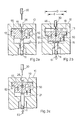
- Fig. 2a shows a relaxed starting position of the spindle 10.
- the differential piston 12 is in the unlocked bush 26 at the upper stop, namely on the upper end face 55, because of a certain residual pressure in the pressure accumulator 50 and the closed check valve 44 in the third cavity 21 certain overpressure prevails.
- the pull rod 11, which in this position does not clamp any tool at its lower end, is in its upper extreme position.
- the plug 30 is now inserted into the socket 26. It was already clear from FIG. 1 that the plug 30 is seated in the socket 26 in a pressure-tight manner as a result of the O-ring 27 and the contours 28, 29, in such a way that the end-side passage opening 39 allows the pressure fluid to flow out of the central bore 38 of the connector 30 allowed in the stepped bore.
- the length of the central actuating pin 40 is dimensioned such that the ball 46 is lifted from its valve seat when the plug 30 is inserted into the socket 26, in this way to clear the path for the pressure fluid through the central bore 45.
- the arrows shown as lines indicate how the pressure fluid is distributed inside the spindle 10 when the plug 30 has been inserted into the socket 26 and the solenoid valve 32 has been switched to the position not shown in FIG. 1, so that the pressure lines 31 and 33 communicate with each other.
- the pressure fluid flows, on the one hand, into the first cavity 19 and also past the ball 46 lifted from its seat, through the axial bore 45 and the transverse bore 48, into the third cavity 21 and from there via the channel 49 into the pressure accumulator 50 being "charged" this way.
- the differential piston 12 moves along the arrow 60 below and the pull rod 11, which is rigidly connected to the differential piston 12, also moves downward along the arrow 61. This downward movement continues until a mechanical stop is reached or the transverse bore 48 is covered by the axial bore 57 of the spindle 10, in which case, after a short further travel of the differential piston 12 downward, a balance of forces due to an increase in pressure in the third cavity 21 sets.
- the solenoid valve 32 is first switched so that the first cavity 19 is now depressurized.
- the ball 46 which is in the position shown in FIG. 2b outside the engagement area of the actuating pin 40, now returns to its valve seat and blocks the central bore 45.
- the connector 30 is now withdrawn from the spindle 10, ensuring that this happens before the differential piston 12 has moved so far up again that the ball 46 comes into contact with the actuating pin 40 again.
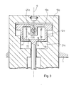
- the further exemplary embodiment of a spindle 10a according to the invention shown in FIG. 3 differs from the previously described exemplary embodiments only in the design of the interior of the differential piston 12a.
- a rotationally symmetrical annular space 70 is provided in the differential piston 12a, which is divided into an outer part 71 and an inner part 72, which in turn are separated from one another by an annular membrane 73, for example a hose membrane.
- the outer part 71 of the annular space 70 is filled with a compressible medium, for example a gas.
- Channels 74 lead from the inner part 72 of the annular space 70 to the third cavity 21a.
- the central bore 45a ends in a connecting piece 75 in the inner part 72 of the annular space 70.
- the mode of operation of the exemplary embodiment shown in FIG. 3 corresponds entirely to that which has already been explained for FIGS. 2a to 2c.
- the fluid under operating pressure enters the first cavity 19a, the third cavity 21a and the inner part 72 of the annular space 70.
- the annular membrane 73 acts together with the outer part 71 of the annular space 70 as a pressure accumulator which is also affected by this action is "charged" to the operating pressure as the differential piston 12a moves downward.
- the ring membrane 73 which was previously deformed outwards, moves inwards again and presses pressure fluid through the channels 74 into the third cavity 21a, so that the differential piston 12a runs up again and clamps the tool.
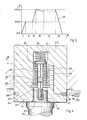
- FIG. 4 shows, in a representation similar to FIG. 1, a further exemplary embodiment of a spindle 10b according to the invention, which in turn is to be rotated about its longitudinal axis in the headstock 1 at a very high speed.
- a tool 80 is to be inserted into the spindle 10b from the underside of the spindle 10b.
- the tool 80 is provided with a circumferential radial shoulder 81, which comes into contact with a parallel outer surface 82 of the spindle 10b when the tool 80 is inserted into the spindle 10b.
- An axial pin 83 of the tool 80 then projects into an axial first bore 84 of the spindle 10b.
- the pin 83 is provided with a central second bore 85, which is designed as a threaded blind bore.
- the pin 83 is inserted into the first bore 84 and by means of the second bore 85, the threaded blind bore, onto a suitable counter thread of a cylindrical one in this area Drawbar 86 screwed, which is located in the axial position in the spindle 10b.
- the pull rod 86 carries a radial disk 87 at its end opposite the threaded section and passes through a guide plate 88 in an area adjacent to the threaded section.
- the guide plate 88 is axially fixed to the edge of the first bore 84.
- the pull rod 86 is out of round in the area passing through the guide plate 88, for example, with a square cross section, as indicated in FIG. 4.
- the associated opening of the guide plate 88 encompasses the non-circular circumference of the pull rod 86 in a form-fitting manner, so that the pull rod 86 is mounted in the spindle 10b in a rotationally fixed but axially displaceable manner within certain limits.
- the torsionally rigid mounting of the pull rod 86 can also take place in another way, for example in that the disk 87 is non-circular and has a positive fit in a correspondingly designed section of the second bore 84 or by other measures known per se for torsionally rigid arrangement of a rod.
- the washer 87 is also supported by a coil spring 90 against a bottom 91 of the first bore 84 opposite the tool 80.
- piezo elements 89 magnetostrictive elements or other elements variable in length by means of electrical energy can also be used.
- the piezo elements 89 shown as an example can be connected in different ways. In the embodiment of FIG. 4, all the piezo elements 89 are connected in parallel by being in the area of an interface an insulated cable 85 is connected, while they are provided with the respective opposite interface with ground connections 96. However, it goes without saying that the piezo elements 89 can, if necessary, also be connected in series or in groups in series / parallel, depending on how expedient in the individual case.
- the insulated cable 95 is guided through the spindle 10b to an insulated socket 97, which has a contact or sliding contact 98 or another electrical connection means, for example a form-fitting plug, on its outside.
- a grinder 99 is connected to an adjustable current source 100 as a separate element. If the grinder 99 touches the sliding contact 98, voltage is present at the piezo elements 89, so that these expand or contract in the axial direction depending on the set current or voltage. It is particularly preferred if the sliding contact 98 rotates in the circumferential direction around the spindle 10b, as indicated by 97 ⁇ , 98 ⁇ , because then, even when the spindle 10b is rotating, the grinder 99 can be in continuous contact with the sliding contact 98.
- FIG. 5 shows a possible procedure for clamping and tightening the tool 8 in the exemplary embodiment in FIGS. 1 or 3 or 80 in the exemplary embodiment in FIG. 4.
- FIG. 5 illustrates a feed path s which is plotted over time t.
- the pull rod 11 or 86 is already drawn in by 50% of the total possible feed path s. In the embodiment of FIG. 4, this can be done, for example, by applying half the nominal voltage to the piezo elements 89.
- the tools 8 and 80 are manually inserted into the spindle 10 and 10b, e.g. 4 loosely screwed by hand to the lower end of the pull rod 86 in the manner shown in FIG.
- the pull rod 86 is now drawn in by 100% of this path by the full clamping path s and the tool 8 or 80 is thus firmly clamped to the spindle 10 or 10b.
- the piezo elements 89 can now be recharged from time to time in subsequent phases IV and V, provided that these should partially discharge over time due to leakage currents.
- the pull rod 11 or 86 is extended again to 0% of the clamping path s, i.e. by 50% of the path corresponds to the position in which the tool 8 or 80 was inserted by hand. Since the tool now protrudes from the spindle 10 or 10b by a piece, namely by 50% of the full clamping path s, the tool 8 or 80 can easily be released.
Landscapes
- Engineering & Computer Science (AREA)
- Mechanical Engineering (AREA)
- Gripping On Spindles (AREA)
Applications Claiming Priority (2)
| Application Number | Priority Date | Filing Date | Title |
|---|---|---|---|
| DE3617103 | 1986-05-21 | ||
| DE3617103A DE3617103C1 (de) | 1986-05-21 | 1986-05-21 | Mit einer Werkzeugspanneinrichtung versehene Spindel einer Werkzeugmaschine |
Publications (3)
| Publication Number | Publication Date |
|---|---|
| EP0246565A2 true EP0246565A2 (fr) | 1987-11-25 |
| EP0246565A3 EP0246565A3 (en) | 1988-12-28 |
| EP0246565B1 EP0246565B1 (fr) | 1991-08-28 |
Family
ID=6301309
Family Applications (1)
| Application Number | Title | Priority Date | Filing Date |
|---|---|---|---|
| EP87107027A Expired - Lifetime EP0246565B1 (fr) | 1986-05-21 | 1987-05-14 | Broche d'une machine-outil |
Country Status (4)
| Country | Link |
|---|---|
| US (1) | US4746252A (fr) |
| EP (1) | EP0246565B1 (fr) |
| JP (1) | JPS62282806A (fr) |
| DE (2) | DE3617103C1 (fr) |
Cited By (1)
| Publication number | Priority date | Publication date | Assignee | Title |
|---|---|---|---|---|
| GB2212746A (en) * | 1987-11-24 | 1989-08-02 | Okuma Machinery Works Ltd | Tool mounting apparatus |
Families Citing this family (12)
| Publication number | Priority date | Publication date | Assignee | Title |
|---|---|---|---|---|
| DE3901179A1 (de) * | 1988-01-19 | 1989-08-03 | Gedib Ingenieurbuero U Innovat | Spannvorrichtung fuer werkzeugmaschinen |
| DE3824581A1 (de) * | 1988-07-19 | 1990-01-25 | Ott Gmbh A | Spanneinrichtung an einer werkzeugmaschinenspindel |
| DE3832582A1 (de) * | 1988-09-24 | 1990-04-05 | Man Technologie Gmbh | Mitlaufender zentrierring mit oelspeicher fuer konstante spannkraft |
| SE512241C2 (sv) * | 1998-06-24 | 2000-02-14 | Sandvik Ab | Hållare för lösgörbar montering av skärverktyg |
| SE512321C2 (sv) * | 1999-03-23 | 2000-02-28 | Lind Finance & Dev Ab | Anordning vid verktygsspindel |
| SE519283C2 (sv) * | 1999-03-23 | 2003-02-11 | Lind Finance & Dev Ab | Anordning hos verktygsspindel med en i spindelaxeln roterande och axiellt rörlig dragstång |
| JP4207176B2 (ja) * | 2000-02-18 | 2009-01-14 | Smc株式会社 | 流体圧シリンダ及びそのピストンとロッドの固定方法 |
| US20020045521A1 (en) * | 2000-10-16 | 2002-04-18 | Hideki Mochida | Spindle unit for a machine tool |
| US6749376B2 (en) * | 2000-12-11 | 2004-06-15 | Command Tooling Systems, Llc | Binary machine tool holder |
| DE102006045095B4 (de) | 2006-09-21 | 2008-06-12 | Rattunde & Co Gmbh | Rohrschneidemaschine |
| US8499431B2 (en) * | 2009-10-26 | 2013-08-06 | Robert Bosch Gmbh | Piezoelectric clamping device |
| HUE032837T2 (hu) * | 2011-07-19 | 2017-11-28 | Mauser-Werke Oberndorf Maschb Gmbh | Utánállító rendszer |
Family Cites Families (25)
| Publication number | Priority date | Publication date | Assignee | Title |
|---|---|---|---|---|
| US2509673A (en) * | 1947-05-15 | 1950-05-30 | Union Mfg Co | Fluid pressure operated chuck |
| US3232181A (en) * | 1964-07-24 | 1966-02-01 | Leland F Blatt | Differential area gas cylinder |
| US3374711A (en) * | 1966-02-24 | 1968-03-26 | Pratt & Whitney Inc | Power drawbar |
| US3401604A (en) * | 1967-05-17 | 1968-09-17 | Ind Specialties Inc | Differential area gas cylinder |
| US3492894A (en) * | 1967-10-02 | 1970-02-03 | Heald Machine Co | Machine tool |
| US3645170A (en) * | 1969-08-01 | 1972-02-29 | Theodore A Varouxis | Air cylinder with self-contained pneumatic piston return |
| US3643969A (en) * | 1970-01-12 | 1972-02-22 | Diventco Inc | Plunger operated rotatable collet |
| FR2180150A5 (fr) * | 1972-04-10 | 1973-11-23 | Peugeot & Renault | |
| SU528152A1 (ru) * | 1973-01-15 | 1976-09-15 | Ульяновское Головное Специальное Конструкторское Бюро Тяжелых И Фрезерных Станков | Устройство дл креплени инструмента |
| SU499990A1 (ru) * | 1974-10-29 | 1976-01-25 | Предприятие П/Я В-8852 | Устройство дл зажима инструмента |
| IT1037803B (it) * | 1975-05-02 | 1979-11-20 | Benatti Edmo | Dispositivo di bloccaggio automatico dei portautensili nel mandrino in particolare ma non esclusivamente di macchine fresatrici |
| SU560707A1 (ru) * | 1976-01-07 | 1977-06-05 | Предприятие П/Я В-2750 | Устройство дл автоматического креплени инструмента |
| US4131054A (en) * | 1976-11-08 | 1978-12-26 | Ex-Cell-O Corporation | High speed spindle and draw bar assembly |
| US4135848A (en) * | 1977-05-23 | 1979-01-23 | Kearney & Trecker Corporation | Toolholder clamp for machine tools |
| JPS5610433A (en) * | 1979-07-05 | 1981-02-02 | Kanegafuchi Chem Ind Co Ltd | Manufacture of thermoplastic resin foamed body |
| US4290720A (en) * | 1979-12-17 | 1981-09-22 | R. F. B. Engineering Inc. | Quick self-release and reload tooling device |
| JPS5761438A (en) * | 1980-09-25 | 1982-04-13 | Nissan Motor Co Ltd | Tool shank holder |
| JPS5856745A (ja) * | 1981-09-29 | 1983-04-04 | Riken Seiki Kk | 自動工具交換装置の工具保持装置 |
| JPS5942234A (ja) * | 1982-08-30 | 1984-03-08 | Yamazaki Mazak Corp | 工具ヘツド |
| DE3306823C2 (de) * | 1983-02-26 | 1985-03-28 | Werkzeugmaschinenfabrik Adolf Waldrich Coburg Gmbh & Co, 8630 Coburg | Werkzeughalter für Bohr-, Fräs- und dgl. Werkzeugmaschinen |
| SU1181784A1 (ru) * | 1984-05-14 | 1985-09-30 | Ульяновское Головное Специальное Конструкторское Бюро Тяжелых И Фрезерных Станков | Шпиндельный узел |
| US4583894A (en) * | 1984-07-02 | 1986-04-22 | Ex-Cell-O Corporation | High speed motorized spindle with tool clamping/unclamping mechanism |
| US4640653A (en) * | 1984-07-30 | 1987-02-03 | Schartzman Everett H | Integral spring flexure for use with high speed rotating shafts |
| US4589808A (en) * | 1984-11-16 | 1986-05-20 | Lesnor Maehr Manufacturing Corp. | Power draw bar |
| US4604009A (en) * | 1985-07-12 | 1986-08-05 | Illinois Tool Works Inc. | Tool retention mechanism |
-
1986
- 1986-05-21 DE DE3617103A patent/DE3617103C1/de not_active Expired
-
1987
- 1987-05-14 DE DE8787107027T patent/DE3772446D1/de not_active Expired - Fee Related
- 1987-05-14 EP EP87107027A patent/EP0246565B1/fr not_active Expired - Lifetime
- 1987-05-20 JP JP62121479A patent/JPS62282806A/ja active Pending
- 1987-05-20 US US07/052,629 patent/US4746252A/en not_active Expired - Fee Related
Cited By (2)
| Publication number | Priority date | Publication date | Assignee | Title |
|---|---|---|---|---|
| GB2212746A (en) * | 1987-11-24 | 1989-08-02 | Okuma Machinery Works Ltd | Tool mounting apparatus |
| GB2212746B (en) * | 1987-11-24 | 1991-11-13 | Okuma Machinery Works Ltd | Tool mounting apparatus |
Also Published As
| Publication number | Publication date |
|---|---|
| EP0246565A3 (en) | 1988-12-28 |
| JPS62282806A (ja) | 1987-12-08 |
| US4746252A (en) | 1988-05-24 |
| DE3617103C1 (de) | 1987-08-27 |
| DE3772446D1 (de) | 1991-10-02 |
| EP0246565B1 (fr) | 1991-08-28 |
Similar Documents
| Publication | Publication Date | Title |
|---|---|---|
| DE2101894C3 (de) | Spann- und Lösevorrichtung für Werkzeuge mit konischem Schaft an Werkzeugmaschinen mit umlaufender Werkzeugspindel | |
| DE3936121C1 (fr) | ||
| DE69714781T2 (de) | Hydromechanisches futter | |
| EP0246565A2 (fr) | Broche d'une machine-outil | |
| DE3506901A1 (de) | Werkzeugadapter fuer eine spindel von bohr-, fraes- u.dgl. werkzeugmaschinen | |
| EP0442456A1 (fr) | Mandrin extensible | |
| EP0364821A2 (fr) | Adaptateur d'outil pour une broche de machine-outil | |
| DE2560287C2 (de) | Werkzeugspannvorrichtung | |
| EP2906377B1 (fr) | Adaptateur d'équilibrage ou de mesure | |
| EP3385016A1 (fr) | Dispositif de serrage et unité d'usinage dotée d'un tel dispositif de serrage | |
| EP1855829B1 (fr) | Système de serrage | |
| EP1663555B1 (fr) | Dispositif de serrage | |
| DE69102229T2 (de) | Zentrifugalspindel. | |
| EP3165310A1 (fr) | Dispositif de serrage | |
| EP1660262B1 (fr) | Point d'assemblage d'un outil | |
| DE69902374T2 (de) | Werkzeugwechselgerät | |
| DE4401779C2 (de) | Löseeinrichtung für ein mittels einer eine Spanneinrichtung umfassenden Werkzeug-Aufnahme einer Werkzeugmaschine gelagertes Werkzeug | |
| DE3615743C2 (fr) | ||
| DE3509922C1 (de) | Spannvorrichtung zum Befestigen eines Werkstückhalters oder dergleichen an einer Spindel | |
| DE4239769A1 (de) | Vorrichtung zum Befestigen von Werkzeugen an einer Werkzeugmaschinenspindel oder einem Werkzeughalter | |
| DE102014220933B4 (de) | Werkzeug zur spanenden Bearbeitung von Werkstücken | |
| CH710297A2 (de) | Vorrichtung zum Bearbeiten von Werkstücken. | |
| EP4202393B1 (fr) | Dispositif de serrage pour serrer un composant sur un élément de machine d'une machine d'usinage | |
| DE1765353C2 (de) | Klemmvorrichtung zum Feststellen einer hydraulisch, pneumatisch oder elektrisch axial beweglichen Kolbenstange, insbesondere an elektrisch abtragenden Maschinen | |
| DE4303118A1 (de) | Vorrichtung zum Befestigen von Werkzeugen an einer Werkzeugmaschinenspindel und einem Werkzeughalter |
Legal Events
| Date | Code | Title | Description |
|---|---|---|---|
| PUAI | Public reference made under article 153(3) epc to a published international application that has entered the european phase |
Free format text: ORIGINAL CODE: 0009012 |
|
| AK | Designated contracting states |
Kind code of ref document: A2 Designated state(s): CH DE FR GB IT LI |
|
| PUAL | Search report despatched |
Free format text: ORIGINAL CODE: 0009013 |
|
| AK | Designated contracting states |
Kind code of ref document: A3 Designated state(s): CH DE FR GB IT LI |
|
| 17P | Request for examination filed |
Effective date: 19881230 |
|
| 17Q | First examination report despatched |
Effective date: 19900216 |
|
| GRAA | (expected) grant |
Free format text: ORIGINAL CODE: 0009210 |
|
| AK | Designated contracting states |
Kind code of ref document: B1 Designated state(s): CH DE FR GB IT LI |
|
| PG25 | Lapsed in a contracting state [announced via postgrant information from national office to epo] |
Ref country code: IT Free format text: LAPSE BECAUSE OF FAILURE TO SUBMIT A TRANSLATION OF THE DESCRIPTION OR TO PAY THE FEE WITHIN THE PRE;WARNING: LAPSES OF ITALIAN PATENTS WITH EFFECTIVE DATE BEFORE 2007 MAY HAVE OCCURRED AT ANY TIME BEFORE 2007. THE CORRECT EFFECTIVE DATE MAY BE DIFFERENT FROM THE ONE RECORDED.SCRIBED TIME-LIMIT Effective date: 19910828 Ref country code: FR Effective date: 19910828 Ref country code: GB Effective date: 19910828 |
|
| REF | Corresponds to: |
Ref document number: 3772446 Country of ref document: DE Date of ref document: 19911002 |
|
| EN | Fr: translation not filed | ||
| GBV | Gb: ep patent (uk) treated as always having been void in accordance with gb section 77(7)/1977 [no translation filed] | ||
| PLBE | No opposition filed within time limit |
Free format text: ORIGINAL CODE: 0009261 |
|
| STAA | Information on the status of an ep patent application or granted ep patent |
Free format text: STATUS: NO OPPOSITION FILED WITHIN TIME LIMIT |
|
| 26N | No opposition filed | ||
| PGFP | Annual fee paid to national office [announced via postgrant information from national office to epo] |
Ref country code: CH Payment date: 19930713 Year of fee payment: 7 |
|
| PGFP | Annual fee paid to national office [announced via postgrant information from national office to epo] |
Ref country code: DE Payment date: 19940113 Year of fee payment: 7 |
|
| PG25 | Lapsed in a contracting state [announced via postgrant information from national office to epo] |
Ref country code: CH Effective date: 19940531 Ref country code: LI Effective date: 19940531 |
|
| REG | Reference to a national code |
Ref country code: CH Ref legal event code: PL |
|
| PG25 | Lapsed in a contracting state [announced via postgrant information from national office to epo] |
Ref country code: DE Effective date: 19950201 |