EP0245837B1 - Führungsrohr für medizinische Instrumente - Google Patents
Führungsrohr für medizinische Instrumente Download PDFInfo
- Publication number
- EP0245837B1 EP0245837B1 EP87106861A EP87106861A EP0245837B1 EP 0245837 B1 EP0245837 B1 EP 0245837B1 EP 87106861 A EP87106861 A EP 87106861A EP 87106861 A EP87106861 A EP 87106861A EP 0245837 B1 EP0245837 B1 EP 0245837B1
- Authority
- EP
- European Patent Office
- Prior art keywords
- tube
- tubular body
- resin flow
- resin
- brittle
- Prior art date
- Legal status (The legal status is an assumption and is not a legal conclusion. Google has not performed a legal analysis and makes no representation as to the accuracy of the status listed.)
- Expired
Links
- 229920005989 resin Polymers 0.000 claims description 20
- 239000011347 resin Substances 0.000 claims description 20
- 229920003002 synthetic resin Polymers 0.000 claims description 9
- 239000000057 synthetic resin Substances 0.000 claims description 9
- 239000000463 material Substances 0.000 claims description 8
- 238000001125 extrusion Methods 0.000 claims description 7
- -1 polypropylene Polymers 0.000 claims description 5
- 238000000034 method Methods 0.000 claims description 4
- 239000004743 Polypropylene Substances 0.000 claims description 3
- 229920001155 polypropylene Polymers 0.000 claims description 3
- VGGSQFUCUMXWEO-UHFFFAOYSA-N Ethene Chemical compound C=C VGGSQFUCUMXWEO-UHFFFAOYSA-N 0.000 claims description 2
- 239000005977 Ethylene Substances 0.000 claims description 2
- YCKRFDGAMUMZLT-UHFFFAOYSA-N Fluorine atom Chemical compound [F] YCKRFDGAMUMZLT-UHFFFAOYSA-N 0.000 claims description 2
- 239000004698 Polyethylene Substances 0.000 claims description 2
- 229920001577 copolymer Polymers 0.000 claims description 2
- 239000011737 fluorine Substances 0.000 claims description 2
- 229910052731 fluorine Inorganic materials 0.000 claims description 2
- 229920000573 polyethylene Polymers 0.000 claims description 2
- 229920000642 polymer Polymers 0.000 claims description 2
- 229920005672 polyolefin resin Polymers 0.000 claims description 2
- 210000004204 blood vessel Anatomy 0.000 description 19
- 239000000203 mixture Substances 0.000 description 4
- 238000005336 cracking Methods 0.000 description 3
- 230000002093 peripheral effect Effects 0.000 description 3
- 239000008280 blood Substances 0.000 description 2
- 210000004369 blood Anatomy 0.000 description 2
- 238000005520 cutting process Methods 0.000 description 2
- 230000006355 external stress Effects 0.000 description 2
- 238000004519 manufacturing process Methods 0.000 description 2
- 238000000465 moulding Methods 0.000 description 2
- 239000004033 plastic Substances 0.000 description 2
- 229920003023 plastic Polymers 0.000 description 2
- 230000001105 regulatory effect Effects 0.000 description 2
- 230000003292 diminished effect Effects 0.000 description 1
- 238000007788 roughening Methods 0.000 description 1
- 229920005992 thermoplastic resin Polymers 0.000 description 1
- 238000003466 welding Methods 0.000 description 1
Images


Classifications
-
- A—HUMAN NECESSITIES
- A61—MEDICAL OR VETERINARY SCIENCE; HYGIENE
- A61M—DEVICES FOR INTRODUCING MEDIA INTO, OR ONTO, THE BODY; DEVICES FOR TRANSDUCING BODY MEDIA OR FOR TAKING MEDIA FROM THE BODY; DEVICES FOR PRODUCING OR ENDING SLEEP OR STUPOR
- A61M25/00—Catheters; Hollow probes
- A61M25/01—Introducing, guiding, advancing, emplacing or holding catheters
- A61M25/06—Body-piercing guide needles or the like
- A61M25/0662—Guide tubes
- A61M25/0668—Guide tubes splittable, tear apart
Definitions
- the present invention relates to a synthetic resin tube for guiding a rod-like medical instrument such as a catheter and a guide wire into, for example, a blood vessel and for keeping the medical instrument attached to the blood vessel.
- a flexible tube of synthetic resin is generally used for guiding, for example, a catheter into a blood vessel and for keeping the catheter attached to the blood vessel.
- a guiding tube 1 is mounted to a syringe 2 such that the tip of an inner needle 3 of the syringe 2 projects outward through the tip of the guiding tube 1.
- the inner needle 3 is inserted into a blood vessel 4 until the tip of the guiding tube 1 is positioned within the blood vessel 4, as shown in Fig. 9. Under this condition, the inner needle 3 is withdrawn from the blood vessel 4, with the guiding tube 1 kept attached to the blood vessel 4.
- a catheter 5 is inserted into the guiding tube 1 until the tip of the catheter 5 is positioned within the blood vessel 4, as shown in Fig. 10.
- the presence of an enlarged portion, such as a connector 6 of the catheter makes it quite difficult to withdraw the guiding tube 1 from the catheter 5.
- Japanese Patent Disclosure (Kokai) 56-11069 proposes another measure. Specifically, it is proposed that a guiding tube is provided with a pair of linear bodies extending along the length of the guiding tube and positioned opposite to each other in the radial direction of the guiding tube.
- the linear body is formed of a plastic material foreign to the material forming the main body of the guiding tube.
- the proximal end portion of the guiding tube, which is joined to the inner needle hub is provided with a pair of slits aligned with the linear bodies. After a catheter or the like which is inserted through the guiding tube has been attached to a blood vessel, the proximal end portion of the guiding tube is pulled outward in opposite directions.
- the guiding tube after use is split into two parts along the linear bodies.
- the slits formed in the proximal end portion of the guiding tube facilitate the splitting.
- the linear body tends to be cracked during the after-treatment, such as cutting or edge-processing of the guiding tube, or during transport or the like of the guiding tube, with the result that leakage of blood is likely to take place so as to make the guiding tube unsuitable for use.
- WO 82/03775 teaches that a rupture line or a brittle portion is formed by providing small holes or a combination of small holes and a slit in the thick portion of a tube or a catheter sheath so as to facilitate the splitting of the tube or catheter sheath.
- the catheter sheath is considerably thin and, thus, the sheath wall is considerably thin. It is technically difficult to form small holes in the thin sheath wall. If the holes are unduly small, splitting of the sheath cannot be facilitated sufficiently. If the holes are enlarged for facilitating the splitting, the substantial thickness of the tube wall is diminished, with the result that the hole-formed portion tends to collapse so as to form a groove on the outer surface of the tube. Further, the combination of small holes and a slit makes the process of forming the rupture line complex.
- US-A-3 527 859 discloses that a wire which acts as a baffle is mounted to the die for forming a splitting portion.
- the wire is used for forming a thin portion in a film.
- An object of the present invention is to provide a guiding tube for rod-like medical instruments such as a catheter, which is free from accidental splitting or cracking during the after-treatment in the manufacture or during the handling thereof.
- Another object of this invention is to provide a guiding tube which can be easily removed from, for example, a catheter after the catheter has been inserted through the guiding tube and attached to a blood vessel.
- a tube for guiding rod-like medical instruments into a living body comprising the features as claimed in claim 1.
- a method of producing a tube for guiding rod-like medical instruments into a living body comprising the features as claimed in claim 6.
- an apparatus for producing a tube for guiding rod-like medical instruments into a living body comprising the features as claimed in claim 6.
- guiding tube 11 for medical instruments comprises a tubular body opened at opposite ends in the shape of a hollow tube for guiding a rod-like medical instruments such as a catheter and converged at one end in contact with an inner needle, not shown, and enlarged at the other cylindrical base.
- the tubular body is formed, as shown in Fig. 2, with brittle positions 12a and 12b made at two portions of the circle of the body, i.e., at two positions opposite to each other in the radial direction along the length of the tubular body or along the entire length of the body such that the splitting force along the tubular body is smaller than the force required at the other end, i.e. the circular portion.
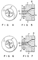
- Brittle portions 12a and 12b of the tubular body are formed with an extrusion molding machine or extruder 13 as shown, for example, in Figs. 4 and 5.
- Molding machine 13 comprises a pair of baffles 15a and 15b positioned oppositely to each other on inner peripheral surface of an inner die 16 and projected oppositely from the inner peripheral surface of the die 16 in the radial direction in an annular passsageway 18 in the vicinity of the nozzle of an annular die 14 such that the molded parts of the tubular body passing baffles 15a and 15b become brittle portions 12a and 12b.
- Baffles 15a and 15b may be determined at the positions and have heights properly in relation to the type and the mixture of synthetic resin to be used.
- the tubular body thus molded is formed substantially smoothly in a continuous circular shape, but is formed with welding lines, i.e., brittle portions 12a, 12b in the portions passing baffles 15a, 15b. Since brittle portions 12a, 12b remarkably decrease in bonding strength between synthetic resins with respect to the rest of the circular portion, portions 12a, 12b are readily broken by applying an external stress thereto, and are, for example, readily split as shown in Fig. 3.
- the splitting strength of brittle portions 12a, 12b may be regulated by adjusting the positions, the heights and the widths (lengths or thicknesses) of the baffles 15a, 15b or arbitrarily adjusting the mixture of two or more resins.
- Thermoplastic resins such as polypropylene, fluorine resin, hydrogenated polyethylene, blend polymer of polyolefin resin and ethylene/vinyl acetate copolymer are properly selectively used as the material of the tubular body of the guiding tube for the medical instruments.
- baffles 15a, 15b are projected on the inner die
- the present invention is not limited to the particular embodiment.
- other appropriate molding means may be employed.
- the same baffles 15a, 15b as those which have been described with reference to Figs. 4 and 5 may be positioned oppositely to the annular die 14 (identical reference numerals designate all the parts as those in Figs. 4 and 5).
- similar baffles may be projected oppositely to annular and inner dies.
- the positions (L), the heights (h) and the sizes of the baffles may be regulated and selected similarly to the case of Figs. 4 and 5.
- Guiding tube 11 of the present invention is, for example, mounted to syringe 2 as shown in Fig. 8 similarly to that shown in Figs. 8 to 10, and is then positioned together with the inner needle of syringe within a blood vessel. Then, the inner needle 3 is withdrawn from the blood vessel, with guiding tube 11 kept attached to the blood vessel 4. Then, a catheter is inserted into the guiding tube 11 so that the catheter is positioned within the blood vessel.
- the catheter has been guided as the guiding tube for medical instruments.
- the present invention is not limited to the catheter, but may be applied to all types of rod-shaped medical instruments which are to be positioned within a living body.
- brittle portions to be split are not limited to the two linear parts as in the embodiments described above, but may be provided with one or three or more linear parts of the brittle portions.
- the guiding tube for the medical instrument according to the present invention as described above is not necessarily provided with the linear bodies formed of a synthetic resin foreign to the material forming the tubular body of the guiding tube as the conventional art but is molded of a sole plastic composition.
- the linear body can avoid to be unintentionally cracked during the after-treatment, such as cutting or edgeprocessing of the guiding tube, the guiding tube can be manufactured readily, leading to a low manufacturing cost of the guiding tube.
- a guiding tube fitting a 16G inner needle was prepared by polypropylene. Even when the tip of the guiding tube was processed in contact with the 16G inner needle, the guiding tube was found to be free of problems such as cracking of the tip portion. Also, the pin portion of the guiding tube was free from roughening, cracking, etc. when the guiding tube was stuck in a blood vessel of a dog together with the inner needle. Further, the linear part was readily peeled from the tubular body for removing the guiding tube.
- a catheter guiding tube was prepared by extrusion molding similarly to the Example 1 except that the similar baffles to those in the Example 1 were disposed at a position of 6 mm before the nozzle of the die. However, in this case, the guiding tube was not substantially molded with brittle portions and could not be split.
Landscapes
- Health & Medical Sciences (AREA)
- Life Sciences & Earth Sciences (AREA)
- Biophysics (AREA)
- Pulmonology (AREA)
- Engineering & Computer Science (AREA)
- Anesthesiology (AREA)
- Biomedical Technology (AREA)
- Heart & Thoracic Surgery (AREA)
- Hematology (AREA)
- Animal Behavior & Ethology (AREA)
- General Health & Medical Sciences (AREA)
- Public Health (AREA)
- Veterinary Medicine (AREA)
- Media Introduction/Drainage Providing Device (AREA)
- Extrusion Moulding Of Plastics Or The Like (AREA)
Claims (6)
- Rohr (11) zum Führen stabförmiger medizinischer Instrumente in einen lebenden Körper, umfassend:
einen aus einem Kunstharz geformten und einen kreisförmigen hohlen Querschnitt einer gleichmäßigen Dicke aufweisenden rohrförmigen Körper und
mindestens einen spröden Abschnitt (12a, 12b), der zum Zeitpunkt des Strangpreßformens beabsichtigt so geformt worden ist, daß seine Spaltfestigkeit kleiner ist als die des anderen Abschnitts über die Gesamtlänge in Längsrichtung des rohrförmigen Körpers oder die Gesamtlänge in Längsrichtung des rohrförmigen Körpers mit Ausnahme seines Endes, und aus dem gleichen Werkstoff wie der andere Abschnitt geformt ist,
dadurch gekennzeichnet, daß der spröde Abschnitt (12a, 12b) eine Schweißlinie oder -naht ist. - Rohr zum Führen stabförmiger medizinischer Instrumente nach Anspruch 1, dadurch gekennzeichnet, daß das distale Ende des rohrförmigen Körpers verjüngt und das proximale Ende des rohrförmigen Körpers erweitert ist.
- Rohr zum Führen stabförmiger medizinischer Instrumente nach Anspruch 1, dadurch gekennzeichnet, daß zwei spröde Abschnitte (12a, 12b) einander in Radialrichtung gegenüberliegend geformt sind.
- Rohr zum Führen stabförmiger medizinischer Instrumente nach Anspruch 1, dadurch gekennzeichnet, daß der hohle rohrförmige Körper aus einem Werkstoff aus der Gruppe Polypropylen, Fluorharz, hydriertes Polyethylen sowie ein Mischpolymeres von Polyolefinharz und Ethylen-Vinylacetat-Mischpolymerisat geformt ist.
- Verfahren zur Herstellung eines Kunstharzrohrs zum Führen stabförmiger medizinischer Instrumente in einen lebenden Körper, umfassend einen rohrförmigen Körper mit einem kreisförmigen hohlen Querschnitt gleichmäßiger Dicke sowie mindestens einen spröden Abschnitt (12a, 12b) und einen anderen Abschnitt, wobei der mindestens eine spröde Abschnitt so geformt ist, daß seine Spaltfestigkeit kleiner ist als die Spaltfestigkeit des anderen Abschnitts über zumindest die Gesamtlänge des rohrförmigen Körpers mit Ausnahme seines Endes, und wobei der mindestens eine spröde Abschnitt aus dem gleichen Werkstoff wie der andere Abschnitt geformt ist, gekennzeichnet durch folgende Schritte:
Formen eines Spaltabschnitts in einem (Kunst-)Harzstrom durch im wesentlichen vorübergehendes Aufspalten oder Auftrennen des Stroms eines Kunstharzes, das in einem Harzströmungsdurchgang (18) innerhalb einer Düse einer Strangpreßform (17) eines Extruders strömt, mit mindestens einer Leitplatte (15a, 15b),
Anordnen der mindestens einen Leitplatte (15a, 15b) so, daß sie radial in die Düse hineinragt und um 0 - 5 mm axial vom Außenende der Düse zurückversetzt ist, wobei die Höhe der mindestens einen Leitplatte mindestens 1/2 der Höhe des Harzströmungsdurchgangs der Strangpreßform (17) beträgt, und
Strangpressen oder Extrudieren des Harzstroms aus einer Düse der Strangpreßform (17) unter Wiedervereinigung des Spaltabschnitts des Harzstroms zur Ausbildung des spröden Abschnitts (12a, 12b) des Harzrohrs am Spaltabschnitt des Harzstroms. - Strangpresse zum Erzeugen eines Kunstharzrohrs zum Führen stabförmiger medizinischer Instrumente in einen lebenden Körper, wobei das Rohr einen rohrförmigen Körper eines kreisförmigen hohlen Querschnitts einer gleichmäßigen Dicke und mindestens einen spröden Abschnitt sowie einen anderen Abschnitt aufweist, wobei der mindestens eine spröde Abschnitt (12a, 12b) so geformt ist, daß seine Spaltfestigkeit kleiner ist als die Spaltfestigkeit des anderen Abschnitts über zumindest die Gesamtlänge des rohrförmigen Körpers mit Ausnahme seines Endes, wobei der mindestens eine spröde Abschnitt aus dem gleichen Werkstoff wie der andere Abschnitt geformt ist, und wobei die Strangpresse eine Strangpreßform (17) mit einer Düse mit Mitteln zum Festlegen eines Harzströmungsdurchgangs eines ringförmigen Querschnitts und mit mindestens einer sich radial in den Harzströmungsdurchgang hineinerstreckenden Leitplatte (15a, 15b) aufweist,
dadurch gekennzeichnet, daß die mindestens eine Leitplatte (15a, 15b) axial (in einem Abstand von) 0 - 5 mm von einem Ende der Düse angeordnet ist und die Höhe der mindestens einen Leitplatte (15a, 15b) mindestens 1/2 der Höhe des Harzströmungsdurchgangs beträgt,
wobei beim Extrudieren des Harzstroms aus der Düse die mindestens eine Leitplatte einen geteilten Abschnitt oder Spaltabschnitt des Harzstroms durch im wesentlichen vorübergehendes Aufspalten des Harzstroms formt, der sodann zur Bildung des spröden Abschnitts (12a, 12b) des Harzrohrs am Spaltabschnitt des Harzstroms wiedervereinigt wird.
Applications Claiming Priority (2)
| Application Number | Priority Date | Filing Date | Title |
|---|---|---|---|
| JP61109922A JPH0611340B2 (ja) | 1986-05-14 | 1986-05-14 | 医療器具導入針の製造方法および製造装置 |
| JP109922/86 | 1986-05-14 |
Publications (3)
| Publication Number | Publication Date |
|---|---|
| EP0245837A2 EP0245837A2 (de) | 1987-11-19 |
| EP0245837A3 EP0245837A3 (en) | 1988-09-28 |
| EP0245837B1 true EP0245837B1 (de) | 1991-10-16 |
Family
ID=14522526
Family Applications (1)
| Application Number | Title | Priority Date | Filing Date |
|---|---|---|---|
| EP87106861A Expired EP0245837B1 (de) | 1986-05-14 | 1987-05-12 | Führungsrohr für medizinische Instrumente |
Country Status (5)
| Country | Link |
|---|---|
| US (2) | US4830805A (de) |
| EP (1) | EP0245837B1 (de) |
| JP (1) | JPH0611340B2 (de) |
| AU (1) | AU591980B2 (de) |
| DE (1) | DE3773738D1 (de) |
Families Citing this family (22)
| Publication number | Priority date | Publication date | Assignee | Title |
|---|---|---|---|---|
| US4883468A (en) * | 1987-04-08 | 1989-11-28 | Terumo Kabushiki Kaisha | Medical tool introduction cannula and method of manufacturing the same |
| JPH02177966A (ja) * | 1988-12-28 | 1990-07-11 | Nippon Zeon Co Ltd | 医療器具導入用チューブの成形方法及びその装置 |
| US4983168A (en) * | 1989-01-05 | 1991-01-08 | Catheter Technology Corporation | Medical layered peel away sheath and methods |
| JPH03292963A (ja) * | 1990-04-10 | 1991-12-24 | Nissho Corp | 易分割性カニューレ |
| JPH05193975A (ja) * | 1991-08-29 | 1993-08-03 | Furukawa Electric Co Ltd:The | 押出し成形式多孔質光ファイバ母材製造装置 |
| JPH0693919B2 (ja) * | 1991-11-25 | 1994-11-24 | 日本ゼオン株式会社 | 医療器具導入用チューブ |
| ES2075772T3 (es) * | 1992-01-08 | 1995-10-01 | Sueddeutsche Feinmechanik | Canula hendida y procedimiento para su fabricacion. |
| DE4200255A1 (de) * | 1992-01-08 | 1993-07-15 | Sueddeutsche Feinmechanik | Spaltkanuele und verfahren zur herstellung einer solchen |
| DE4221820C2 (de) * | 1992-07-03 | 1994-04-28 | Ruesch Willy Ag | Splittbarer Katheter |
| US5329964A (en) * | 1993-09-09 | 1994-07-19 | Eastman Kodak Company | Criss-cross hopper including non-contacting inserts |
| JPH09510922A (ja) * | 1995-01-25 | 1997-11-04 | ジャン−フランソワ、ブュティ | 金属製の中空本体の製造方法及び本方法によって製造される中空本体及び本方法を実施する装置 |
| EP0750381B1 (de) * | 1995-06-21 | 2002-09-18 | Minnesota Mining And Manufacturing Company | Zerbrechbarer Kern und Abdeckeinrichtung mit einem expandierten elastomerischen Rohr und einem zerbrechbaren Kern |
| US5566680A (en) * | 1995-09-22 | 1996-10-22 | Graphic Controls Corporation | Transducer-tipped intrauterine pressure catheter system |
| CA2271056A1 (en) | 1996-11-15 | 1998-05-22 | Cook Incorporated | Splittable sleeve, stent deployment device |
| GB0417664D0 (en) * | 2004-08-07 | 2004-09-08 | Univ Cambridge Tech | Producing tear guiding regions in films |
| US7951116B2 (en) | 2004-11-12 | 2011-05-31 | Boston Scientific Scimed, Inc. | Selective surface modification of catheter tubing |
| AU2006239223B2 (en) | 2005-04-28 | 2010-08-05 | St. Jude Medical, Atrial Fibrillation Division Inc. | Body for a catheter or sheath |
| EP1877126B1 (de) * | 2005-04-28 | 2013-05-22 | St. Jude Medical, Atrial Fibrillation Division, Inc. | Aufspaltbare atraumatische spitze und körper für einen katheter oder eine hülse |
| DE102005035795A1 (de) * | 2005-05-03 | 2006-11-09 | Rheinisch-Westfälisch Technische Hochschule Aachen | Vorrichtung zur Erfassung physiologischer Messgrössen im Körperinneren |
| JP5147231B2 (ja) * | 2006-12-26 | 2013-02-20 | 日本コヴィディエン株式会社 | 医療用チューブの押出成形用金型および押出成形方法 |
| CN108027091B (zh) * | 2015-09-11 | 2020-06-30 | 郡是株式会社 | 氟树脂制撕裂管 |
| WO2024033675A1 (en) | 2022-08-08 | 2024-02-15 | Embrace Medical Ltd | Vascular access wire tip comprising a crank |
Family Cites Families (24)
| Publication number | Priority date | Publication date | Assignee | Title |
|---|---|---|---|---|
| US1184254A (en) * | 1915-05-17 | 1916-05-23 | Peter Mcg Mcbean | Die for the manufacture of tiles. |
| US2149002A (en) * | 1936-01-18 | 1939-02-28 | Belden Mfg Co | Method and apparatus for making divisible electrical conductors |
| US2176233A (en) * | 1936-01-18 | 1939-10-17 | Belden Mfg Co | Divisible electric conductor |
| US2446493A (en) * | 1945-12-07 | 1948-08-03 | Boston Woven Hose & Rubber Co | Jar ring |
| US2524829A (en) * | 1948-04-14 | 1950-10-10 | Standard Telephones Cables Ltd | Extrusion apparatus for coating insulation over wires and cables |
| US3380129A (en) * | 1966-06-29 | 1968-04-30 | Richland Shale Products Co | Extrusion die for drain tile cluster |
| US3535409A (en) * | 1967-01-17 | 1970-10-20 | Tower Products | Method of making sheet material with film tear line |
| US3527859A (en) * | 1967-12-11 | 1970-09-08 | Fmc Corp | Manufacture of scored films |
| US3656479A (en) * | 1970-02-19 | 1972-04-18 | James A Huggins | Detachable guide needle |
| US3713442A (en) * | 1970-09-08 | 1973-01-30 | H Walter | Split needle assembly for catheter tube |
| DE2104226B1 (de) * | 1971-01-29 | 1971-12-02 | Braun Fa B | Vorrichtung zur einf]hrung eines flexiblen katheters |
| US3899283A (en) * | 1973-01-15 | 1975-08-12 | Marvin E Wallis | Apparatus for extruding resin film with weakened tear lines |
| JPS5147961A (en) * | 1974-10-24 | 1976-04-24 | Niigata Kako Kk | Haisendakutono seikei hoho oyobisoreni shosuru oshidashidai |
| US4054136A (en) * | 1975-03-03 | 1977-10-18 | Zeppelin Dieter Von | Cannula for the introduction of a catheter |
| US4229407A (en) * | 1979-02-23 | 1980-10-21 | Baxter Travenol Laboratories, Inc. | Tear path products, method and apparatus |
| DE2926572C2 (de) * | 1979-06-30 | 1982-04-15 | B. Braun Melsungen Ag, 3508 Melsungen | Teilbarer Kurzkatheter aus Kunststoff |
| US4330497A (en) * | 1981-01-19 | 1982-05-18 | Sherwood Medical Industries Inc. | Method of making grooved plastic medical tubing |
| DE3107983A1 (de) * | 1981-03-03 | 1982-09-16 | Max Dr. 8520 Erlangen Hubmann | Katheterbesteck |
| US4411654A (en) * | 1981-04-30 | 1983-10-25 | Baxter Travenol Laboratories, Inc. | Peelable catheter with securing ring and suture sleeve |
| AU8523582A (en) * | 1981-04-30 | 1982-11-24 | Baxter Travenol Laboratories Inc. | Peelable catheter introduction device |
| DE3117802A1 (de) * | 1981-05-06 | 1982-11-25 | Max Dr. 8520 Erlangen Hubmann | Katheterbesteck |
| AU1474183A (en) * | 1982-04-22 | 1983-11-21 | Gustavsson Bengt | Anordning for inforande av katetrar i ett blodkarl |
| US4581025A (en) * | 1983-11-14 | 1986-04-08 | Cook Incorporated | Sheath |
| JPS62101261A (ja) * | 1985-10-28 | 1987-05-11 | テルモ株式会社 | 医療器具導入用チユ−ブおよびそれを備えた医療器具導入用組立体 |
-
1986
- 1986-05-14 JP JP61109922A patent/JPH0611340B2/ja not_active Expired - Lifetime
-
1987
- 1987-05-11 US US07/048,675 patent/US4830805A/en not_active Expired - Fee Related
- 1987-05-12 EP EP87106861A patent/EP0245837B1/de not_active Expired
- 1987-05-12 DE DE8787106861T patent/DE3773738D1/de not_active Expired - Fee Related
- 1987-05-13 AU AU72968/87A patent/AU591980B2/en not_active Ceased
-
1988
- 1988-11-09 US US07/269,727 patent/US4919605A/en not_active Expired - Fee Related
Also Published As
| Publication number | Publication date |
|---|---|
| JPS62266077A (ja) | 1987-11-18 |
| EP0245837A3 (en) | 1988-09-28 |
| US4919605A (en) | 1990-04-24 |
| JPH0611340B2 (ja) | 1994-02-16 |
| US4830805A (en) | 1989-05-16 |
| EP0245837A2 (de) | 1987-11-19 |
| AU7296887A (en) | 1987-12-17 |
| DE3773738D1 (de) | 1991-11-21 |
| AU591980B2 (en) | 1989-12-21 |
Similar Documents
| Publication | Publication Date | Title |
|---|---|---|
| EP0245837B1 (de) | Führungsrohr für medizinische Instrumente | |
| EP0238018B1 (de) | Führungsrohr für medizinische Instrumente | |
| US4747833A (en) | Medical instrument-guiding tube and assembly comprising the same | |
| US4883468A (en) | Medical tool introduction cannula and method of manufacturing the same | |
| EP0279015B1 (de) | Verbundwerkstoff und Verfahren für aufspaltbaren Katheter | |
| US4952359A (en) | Method for making splittable catheter | |
| US4402685A (en) | Dividable catheter | |
| US6508966B1 (en) | Splittable tubular medical device and method for manufacture | |
| KR101015624B1 (ko) | 카테테르 슬리이브 조립체 및, 그것을 제조하기 위한 단일단계의 사출 성형 방법 | |
| US5188605A (en) | Separable insertion tool | |
| CA2256654C (en) | One-step flashing bevel process | |
| US12042612B2 (en) | Split sheath introducer and method of manufacturing a split sheath introducer | |
| EP0341830B1 (de) | Spaltbarer Einführungskatheter mit modifizierter Spitze | |
| JP2004321223A (ja) | インサーター、その製造方法及びカテーテル | |
| JPH0315915B2 (de) | ||
| JP2554554B2 (ja) | 医療器具導入針 | |
| CN117257424B (zh) | 可撕裂鞘管及其制造方法 | |
| CN115003259A (zh) | 支架输送装置和导引导管 | |
| JP3324109B2 (ja) | 留置針外針の先端成形方法 | |
| JPH0353949B2 (de) |
Legal Events
| Date | Code | Title | Description |
|---|---|---|---|
| PUAI | Public reference made under article 153(3) epc to a published international application that has entered the european phase |
Free format text: ORIGINAL CODE: 0009012 |
|
| 17P | Request for examination filed |
Effective date: 19870609 |
|
| AK | Designated contracting states |
Kind code of ref document: A2 Designated state(s): BE DE FR GB IT SE |
|
| PUAL | Search report despatched |
Free format text: ORIGINAL CODE: 0009013 |
|
| AK | Designated contracting states |
Kind code of ref document: A3 Designated state(s): BE DE FR GB IT SE |
|
| 17Q | First examination report despatched |
Effective date: 19900417 |
|
| GRAA | (expected) grant |
Free format text: ORIGINAL CODE: 0009210 |
|
| AK | Designated contracting states |
Kind code of ref document: B1 Designated state(s): BE DE FR GB IT SE |
|
| ITF | It: translation for a ep patent filed | ||
| REF | Corresponds to: |
Ref document number: 3773738 Country of ref document: DE Date of ref document: 19911121 |
|
| ET | Fr: translation filed | ||
| PLBE | No opposition filed within time limit |
Free format text: ORIGINAL CODE: 0009261 |
|
| STAA | Information on the status of an ep patent application or granted ep patent |
Free format text: STATUS: NO OPPOSITION FILED WITHIN TIME LIMIT |
|
| 26N | No opposition filed | ||
| EAL | Se: european patent in force in sweden |
Ref document number: 87106861.5 |
|
| PGFP | Annual fee paid to national office [announced via postgrant information from national office to epo] |
Ref country code: GB Payment date: 19950501 Year of fee payment: 9 |
|
| PGFP | Annual fee paid to national office [announced via postgrant information from national office to epo] |
Ref country code: FR Payment date: 19950510 Year of fee payment: 9 |
|
| PGFP | Annual fee paid to national office [announced via postgrant information from national office to epo] |
Ref country code: DE Payment date: 19950511 Year of fee payment: 9 |
|
| PGFP | Annual fee paid to national office [announced via postgrant information from national office to epo] |
Ref country code: SE Payment date: 19950517 Year of fee payment: 9 |
|
| PGFP | Annual fee paid to national office [announced via postgrant information from national office to epo] |
Ref country code: BE Payment date: 19950712 Year of fee payment: 9 |
|
| PG25 | Lapsed in a contracting state [announced via postgrant information from national office to epo] |
Ref country code: GB Effective date: 19960512 |
|
| PG25 | Lapsed in a contracting state [announced via postgrant information from national office to epo] |
Ref country code: SE Effective date: 19960513 |
|
| PG25 | Lapsed in a contracting state [announced via postgrant information from national office to epo] |
Ref country code: BE Effective date: 19960531 |
|
| BERE | Be: lapsed |
Owner name: TERUMO K.K. Effective date: 19960531 |
|
| GBPC | Gb: european patent ceased through non-payment of renewal fee |
Effective date: 19960512 |
|
| PG25 | Lapsed in a contracting state [announced via postgrant information from national office to epo] |
Ref country code: FR Effective date: 19970131 |
|
| PG25 | Lapsed in a contracting state [announced via postgrant information from national office to epo] |
Ref country code: DE Effective date: 19970201 |
|
| EUG | Se: european patent has lapsed |
Ref document number: 87106861.5 |
|
| REG | Reference to a national code |
Ref country code: FR Ref legal event code: ST |
|
| PG25 | Lapsed in a contracting state [announced via postgrant information from national office to epo] |
Ref country code: IT Free format text: LAPSE BECAUSE OF NON-PAYMENT OF DUE FEES;WARNING: LAPSES OF ITALIAN PATENTS WITH EFFECTIVE DATE BEFORE 2007 MAY HAVE OCCURRED AT ANY TIME BEFORE 2007. THE CORRECT EFFECTIVE DATE MAY BE DIFFERENT FROM THE ONE RECORDED. Effective date: 20050512 |