EP0245196A2 - Méthode de transmission de données entre une partie fixe et une partie mobile - Google Patents
Méthode de transmission de données entre une partie fixe et une partie mobile Download PDFInfo
- Publication number
- EP0245196A2 EP0245196A2 EP87730045A EP87730045A EP0245196A2 EP 0245196 A2 EP0245196 A2 EP 0245196A2 EP 87730045 A EP87730045 A EP 87730045A EP 87730045 A EP87730045 A EP 87730045A EP 0245196 A2 EP0245196 A2 EP 0245196A2
- Authority
- EP
- European Patent Office
- Prior art keywords
- stationary part
- frequency
- low
- oscillator
- transmitted
- Prior art date
- Legal status (The legal status is an assumption and is not a legal conclusion. Google has not performed a legal analysis and makes no representation as to the accuracy of the status listed.)
- Granted
Links
- 230000005540 biological transmission Effects 0.000 title claims abstract description 5
- 230000010355 oscillation Effects 0.000 claims abstract description 11
- 230000001360 synchronised effect Effects 0.000 claims abstract description 8
- 230000002457 bidirectional effect Effects 0.000 claims abstract description 3
- 239000003990 capacitor Substances 0.000 claims description 3
- 230000002123 temporal effect Effects 0.000 claims 1
- 238000010586 diagram Methods 0.000 description 7
- 230000015654 memory Effects 0.000 description 6
- 230000010363 phase shift Effects 0.000 description 5
- 230000008054 signal transmission Effects 0.000 description 3
- 239000000969 carrier Substances 0.000 description 1
- 230000008878 coupling Effects 0.000 description 1
- 238000010168 coupling process Methods 0.000 description 1
- 238000005859 coupling reaction Methods 0.000 description 1
- 238000001514 detection method Methods 0.000 description 1
- 230000007613 environmental effect Effects 0.000 description 1
- 238000011156 evaluation Methods 0.000 description 1
- 230000006870 function Effects 0.000 description 1
- 230000001939 inductive effect Effects 0.000 description 1
- 230000010354 integration Effects 0.000 description 1
- 230000001502 supplementing effect Effects 0.000 description 1
Images


Classifications
-
- H04B5/266—
-
- G—PHYSICS
- G06—COMPUTING; CALCULATING OR COUNTING
- G06K—GRAPHICAL DATA READING; PRESENTATION OF DATA; RECORD CARRIERS; HANDLING RECORD CARRIERS
- G06K7/00—Methods or arrangements for sensing record carriers, e.g. for reading patterns
- G06K7/0008—General problems related to the reading of electronic memory record carriers, independent of its reading method, e.g. power transfer
-
- H—ELECTRICITY
- H04—ELECTRIC COMMUNICATION TECHNIQUE
- H04L—TRANSMISSION OF DIGITAL INFORMATION, e.g. TELEGRAPHIC COMMUNICATION
- H04L27/00—Modulated-carrier systems
- H04L27/18—Phase-modulated carrier systems, i.e. using phase-shift keying
- H04L27/22—Demodulator circuits; Receiver circuits
- H04L27/233—Demodulator circuits; Receiver circuits using non-coherent demodulation
- H04L27/2335—Demodulator circuits; Receiver circuits using non-coherent demodulation using temporal properties of the received signal
- H04L27/2337—Demodulator circuits; Receiver circuits using non-coherent demodulation using temporal properties of the received signal using digital techniques to measure the time between zero-crossings
Definitions
- the problem of monodirectional signal transmission is solved by using and using circuits based on the principle of the synchronous switch.
- signals from a moving part such as a key or chip card, are transmitted at certain points in time, which are marked by counting oscillation half-waves, by short-circuiting a coil.
- Such systems are already used in the lock and key area.
- the invention is based on the object of supplementing these systems in such a way that signals can be transmitted from the predominantly stationary part to the movable part (for example from the lock to the key) according to the principle of the phase jump, without an additional coil being used and also the geometric one , External structure of the transmission components remains the same and existing receiving electronics continue to function according to the principle of the synchronous switch, even when using the invention described here, and can receive signals from the predominantly movable electronic part.
- phase jump In addition to the integration of the synchronous switch principle, it was necessary to find such an evaluation of a phase jump, which can be miniaturized easily by switching and can therefore be accommodated as an IC on a movable carrier, such as a key or a chip card. Larger components, such as coils or capacitors or resistors, which are difficult to implement in the field of digital circuits, should preferably not be required for the circuit. The circuit should also be extremely stable against environmental influences.
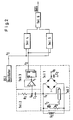
- FIG 1 shows the generation of a phase jump using the EXOR element (EX1).
- the signal data are synchronized by the flip-flop (FF1) with the text of the oscillator (OS1).
- the base of transistor T1 is connected to the output of EX1.
- T1 forces the resonant circuit, consisting of capacitor C1 and coil S1, to the frequency specified by oscillator OS1.
- Via coil S1 there is an inductive coupling to coil S2 in Figure 2. From this arrangement in Figure 1 it can be seen that a change in state of the signal data line (S) results in a phase shift of 180 of oscillation fx, which is transmitted via S1 to S2 .
- DE-PS 31 49 789 this principle is described without the phase shift.
- Figure 2 shows the block diagram of the predominantly moving part for the detection of the phase shift and details of parts 1, 2 and 3.
- the required operating voltage of the predominantly moving part is obtained from the direct voltage part of the vibration fx 'transmitted from S1 to S2 in the stationary part 1. Furthermore, e.g. Via the transistor T2 and the resistor R2, the coil S2 is short-circuited via a circuit part 7 at times which is determined by counting half-waves of the frequency fx.
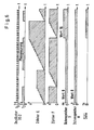
- the AC voltage part ( Figure 4, diagram fm) of the vibration fx ' is filtered out.
- Circuit part 3 forms rectangular pulses from the AC voltage part filtered out in part 2, in such a way that, if there is no phase jump, the high signals are just as long as the low signals ( Figure 4, diagram f2).
- Circuit part 5 counts the positive edges of the fixed oscillating frequency fo while the low signal from f2 is present.
- Circuit part 4 counts the positive edges of the fixed oscillating frequency fo while the high signal of f2 is present.
- the fixed oscillating frequency fo is generated by the oscillator OS2 on the predominantly moving part, the frequency of which is higher than that of the oscillator OS1 on the predominantly stationary part.
- Circuit part 6 subtracts the number of positive edges counted by circuit parts 4 and 5 from each other. From the difference between these numbers, a phase jump on the part of the stationary part can be concluded, with which the output DATA of circuit part 6 can be set to high.
- Circuit part 3 consists of an overdriven operational amplifier and a flip-flop.
- the operational amplifier converts the sinusoidal AC voltage into square-wave pulses, so that the duration of the positive half-waves corresponds to the duration of the high signal, and the duration of the negative half-wave corresponds to the duration of the low signal.
- the positive and the negative half-wave of the AC voltage part should have different lengths, the circuit for detecting the phase jump would incorrectly recognize a phase jump, as is clear from the above description.
- a flip-flop is connected downstream of the operational amplifier, so that a period of the oscillation fm corresponds to the duration of the high or low signal.
- Figure 3 shows a possible configuration of the circuit parts 4, 5, 6.
- the AND gates A and B determine when the counting circuit following behind is activated.
- Component C forms the amount of the difference in the contents of the data memory G and H.
- Component D sets its output to high if the magnitude of the difference is greater than 1.
- the diagrams in Figure 6 illustrate the further mode of operation.
- Figure 4 shows how the alternating voltage component of the oscillation fx 'becomes rectangular pulses for further digital processing on the basis of diagrams belonging to Figure 2.
- Figure 5 shows how the alternating voltage component of the oscillation fx 'becomes rectangular pulses for digital further processing on the basis of diagrams belonging to Figure 2.
- Figure 5 makes it clear that it does not matter how the oscillation behaves during the phase shift, since the phase shift by 180 means that the duration of the signals must vary from high to low.
- the comparator (circuit part G) compares the numbers stored in G and H and outputs the signal DATA (according to Fig. 3 and Fig. G).
- the circuit fulfills the requirements set out at the beginning.
- the additional circuitry for circuits that work according to the principle of the synchronous switch is limited and almost exclusively digital and therefore can be miniaturized without problems.
Priority Applications (1)
| Application Number | Priority Date | Filing Date | Title |
|---|---|---|---|
| AT87730045T ATE64801T1 (de) | 1986-04-29 | 1987-04-27 | Verfahren zur datenuebertragung zwischen einem festen teil und einem beweglichen teil. |
Applications Claiming Priority (2)
| Application Number | Priority Date | Filing Date | Title |
|---|---|---|---|
| DE19863614477 DE3614477A1 (de) | 1986-04-29 | 1986-04-29 | Vorrichtung zur bidirektionalen datenuebertragung |
| DE3614477 | 1986-04-29 |
Publications (3)
| Publication Number | Publication Date |
|---|---|
| EP0245196A2 true EP0245196A2 (fr) | 1987-11-11 |
| EP0245196A3 EP0245196A3 (en) | 1988-03-16 |
| EP0245196B1 EP0245196B1 (fr) | 1991-06-26 |
Family
ID=6299774
Family Applications (1)
| Application Number | Title | Priority Date | Filing Date |
|---|---|---|---|
| EP87730045A Expired - Lifetime EP0245196B1 (fr) | 1986-04-29 | 1987-04-27 | Méthode de transmission de données entre une partie fixe et une partie mobile |
Country Status (5)
| Country | Link |
|---|---|
| US (1) | US4796028A (fr) |
| EP (1) | EP0245196B1 (fr) |
| JP (1) | JPS62261242A (fr) |
| AT (1) | ATE64801T1 (fr) |
| DE (1) | DE3614477A1 (fr) |
Cited By (14)
| Publication number | Priority date | Publication date | Assignee | Title |
|---|---|---|---|---|
| DE4017934A1 (de) * | 1990-06-05 | 1992-01-02 | Josef Thomas Wanisch | Einrichtung zur drahtlosen informationsabfrage von einer antwortstation, bei der die antwortstation durch das drahtlose abfragesignal einer abfragestation mit der notwendigen energie versorgt wird |
| EP0649110A1 (fr) * | 1993-10-18 | 1995-04-19 | France Telecom | Dispositif à pureté spectrale pour l'échange d'informations à distance entre un objet portatif et une station |
| US6018299A (en) * | 1998-06-09 | 2000-01-25 | Motorola, Inc. | Radio frequency identification tag having a printed antenna and method |
| US6040773A (en) * | 1995-10-11 | 2000-03-21 | Motorola, Inc. | Radio frequency identification tag arranged for magnetically storing tag state information |
| US6107920A (en) * | 1998-06-09 | 2000-08-22 | Motorola, Inc. | Radio frequency identification tag having an article integrated antenna |
| US6229442B1 (en) | 2000-03-14 | 2001-05-08 | Motorola, Inc, | Radio frequency identification device having displacement current control and method thereof |
| US6236316B1 (en) | 1999-01-05 | 2001-05-22 | Motorola, Inc. | Transport device with openings for capacitive coupled readers |
| US6246327B1 (en) | 1998-06-09 | 2001-06-12 | Motorola, Inc. | Radio frequency identification tag circuit chip having printed interconnection pads |
| US6252508B1 (en) | 1995-10-11 | 2001-06-26 | Motorola, Inc. | Radio frequency identification tag arranged for magnetically storing tag state information |
| US6265977B1 (en) | 1998-09-11 | 2001-07-24 | Motorola, Inc. | Radio frequency identification tag apparatus and related method |
| US6362738B1 (en) | 1998-04-16 | 2002-03-26 | Motorola, Inc. | Reader for use in a radio frequency identification system and method thereof |
| US6411213B1 (en) | 1995-10-11 | 2002-06-25 | Motorola, Inc. | Radio frequency identification tag system using tags arranged for coupling to ground |
| US6496112B1 (en) | 1998-02-27 | 2002-12-17 | Motorola, Inc. | Radio frequency identification tag with a programmable circuit state |
| US6611199B1 (en) | 1995-10-11 | 2003-08-26 | Motorola, Inc. | Capacitively powered portable communication device and associated exciter/reader and related method |
Families Citing this family (13)
| Publication number | Priority date | Publication date | Assignee | Title |
|---|---|---|---|---|
| DE3912497A1 (de) * | 1989-04-15 | 1990-10-18 | Daimler Benz Ag | Gleichzeitige energie- und datenrueckuebertragung ueber lose transformatorische kupplung |
| ATE135835T1 (de) * | 1990-07-16 | 1996-04-15 | Siemens Ag | Einrichtung zur berührungslosen daten- und energieübertragung sowie verwendung einer solchen |
| AT395224B (de) * | 1990-08-23 | 1992-10-27 | Mikron Ges Fuer Integrierte Mi | Kontaktloses, induktives datenuebertragungssystem |
| DE4038970A1 (de) * | 1990-12-06 | 1992-06-11 | Schlafhorst & Co W | Verfahren und einrichtung zur bidirektionalen datenuebermittlung zwischen einer textilmaschine und einem textilen produkt |
| DE4230148C2 (de) * | 1992-09-09 | 1994-08-25 | Angewandte Digital Elektronik | Schaltungsanordnung zum Nachweis einer Unterbrechung der elektrischen Verbindung von kontaktfrei arbeitenden Chipkarten zu ihrem Schreib/Lesegerät |
| DE4240238C2 (de) * | 1992-11-30 | 1995-01-05 | Angewandte Digital Elektronik | Einrichtung zur berührungslosen Energie- und Datenübertragung für Einspulen- und Zweispulensysteme |
| US5736967A (en) * | 1993-09-03 | 1998-04-07 | Kayser Ventures, Ltd. | Article-information display system using electronically controlled tags |
| US6181299B1 (en) | 1993-09-03 | 2001-01-30 | Display Edge Technology, Ltd. | Power and communication system for electronic display tags |
| US6266052B1 (en) | 1993-09-03 | 2001-07-24 | Display Edge Technology, Ltd. | Power and information distribution system for article display or storage areas and related method |
| US6249263B1 (en) | 1993-09-03 | 2001-06-19 | Display Edge Technology, Ltd. | Article-information display system using electronically controlled tags |
| DE19726335C2 (de) | 1997-06-20 | 2000-03-02 | Angewandte Digital Elektronik | Chipkarte mit mindestens zwei Spulenanordnungen zur Übertragung von Daten und/oder Energie |
| DE19800565C2 (de) * | 1998-01-09 | 2000-06-29 | Siemens Ag | Datenübertragungssystem mit einem beweglichen Transponder und einer Basisstation |
| WO2012026343A1 (fr) * | 2010-08-24 | 2012-03-01 | Semiconductor Energy Laboratory Co., Ltd. | Dispositif à semi-conducteurs |
Citations (1)
| Publication number | Priority date | Publication date | Assignee | Title |
|---|---|---|---|---|
| DE2658499A1 (de) * | 1976-01-13 | 1977-07-14 | Asea Ab | Anordnung zur kontaktlosen uebertragung von signalen zwischen einem ortsfesten und einem beweglichen teil einer maschine |
Family Cites Families (8)
| Publication number | Priority date | Publication date | Assignee | Title |
|---|---|---|---|---|
| US3088099A (en) * | 1960-09-19 | 1963-04-30 | W W Henry Company | Data communication system |
| US3488632A (en) * | 1967-02-20 | 1970-01-06 | William T Clark | Infinitely variable inductive remote control system |
| DE3149789C1 (de) * | 1981-12-16 | 1983-08-25 | Angewandte Digital Elektronik Gmbh, 2051 Brunstorf | Vorrichtung zur induktiven Identifizierung einer Information |
| US4549176A (en) * | 1983-04-01 | 1985-10-22 | Angewandte Digital Elektronik Gmbh | Device for identifying an information particularly an electronic lock/key combination |
| DE3402737C1 (de) * | 1984-01-27 | 1985-08-01 | Angewandte Digital Elektronik Gmbh, 2051 Brunstorf | Vorrichtung zur gegenseitigen Informationsuebertragung |
| US4654658A (en) * | 1984-08-03 | 1987-03-31 | Walton Charles A | Identification system with vector phase angle detection |
| DE3447560A1 (de) * | 1984-12-21 | 1986-07-10 | Angewandte Digital Elektronik Gmbh, 2051 Brunstorf | Einrichtung zur beruehrungslosen signal- und energieuebertragung |
| US4656472A (en) * | 1985-01-23 | 1987-04-07 | Walton Charles A | Proximity identification system with power aided identifier |
-
1986
- 1986-04-29 DE DE19863614477 patent/DE3614477A1/de active Granted
-
1987
- 1987-04-17 US US07/039,436 patent/US4796028A/en not_active Expired - Lifetime
- 1987-04-27 EP EP87730045A patent/EP0245196B1/fr not_active Expired - Lifetime
- 1987-04-27 AT AT87730045T patent/ATE64801T1/de not_active IP Right Cessation
- 1987-04-28 JP JP62103449A patent/JPS62261242A/ja active Pending
Patent Citations (1)
| Publication number | Priority date | Publication date | Assignee | Title |
|---|---|---|---|---|
| DE2658499A1 (de) * | 1976-01-13 | 1977-07-14 | Asea Ab | Anordnung zur kontaktlosen uebertragung von signalen zwischen einem ortsfesten und einem beweglichen teil einer maschine |
Non-Patent Citations (1)
| Title |
|---|
| IEEE TRANSACTIONS ON COMMUNICATIONS, Band COM-21, Nr. 12, Dezember 1973, Seiten 1352-1360, V.O. HENTINEN et al.: "A digital demodulator for PSK signals" * |
Cited By (16)
| Publication number | Priority date | Publication date | Assignee | Title |
|---|---|---|---|---|
| DE4017934A1 (de) * | 1990-06-05 | 1992-01-02 | Josef Thomas Wanisch | Einrichtung zur drahtlosen informationsabfrage von einer antwortstation, bei der die antwortstation durch das drahtlose abfragesignal einer abfragestation mit der notwendigen energie versorgt wird |
| EP0649110A1 (fr) * | 1993-10-18 | 1995-04-19 | France Telecom | Dispositif à pureté spectrale pour l'échange d'informations à distance entre un objet portatif et une station |
| FR2711440A1 (fr) * | 1993-10-18 | 1995-04-28 | France Telecom | Dispositif à pureté spectrale pour l'échange d'informations à distance entre un objet portatif et une station. |
| US5734333A (en) * | 1993-10-18 | 1998-03-31 | France Telecom | Device with spectral purity for the remote exchange of information between a portable object and a station |
| US6252508B1 (en) | 1995-10-11 | 2001-06-26 | Motorola, Inc. | Radio frequency identification tag arranged for magnetically storing tag state information |
| US6040773A (en) * | 1995-10-11 | 2000-03-21 | Motorola, Inc. | Radio frequency identification tag arranged for magnetically storing tag state information |
| US6611199B1 (en) | 1995-10-11 | 2003-08-26 | Motorola, Inc. | Capacitively powered portable communication device and associated exciter/reader and related method |
| US6411213B1 (en) | 1995-10-11 | 2002-06-25 | Motorola, Inc. | Radio frequency identification tag system using tags arranged for coupling to ground |
| US6496112B1 (en) | 1998-02-27 | 2002-12-17 | Motorola, Inc. | Radio frequency identification tag with a programmable circuit state |
| US6362738B1 (en) | 1998-04-16 | 2002-03-26 | Motorola, Inc. | Reader for use in a radio frequency identification system and method thereof |
| US6018299A (en) * | 1998-06-09 | 2000-01-25 | Motorola, Inc. | Radio frequency identification tag having a printed antenna and method |
| US6246327B1 (en) | 1998-06-09 | 2001-06-12 | Motorola, Inc. | Radio frequency identification tag circuit chip having printed interconnection pads |
| US6107920A (en) * | 1998-06-09 | 2000-08-22 | Motorola, Inc. | Radio frequency identification tag having an article integrated antenna |
| US6265977B1 (en) | 1998-09-11 | 2001-07-24 | Motorola, Inc. | Radio frequency identification tag apparatus and related method |
| US6236316B1 (en) | 1999-01-05 | 2001-05-22 | Motorola, Inc. | Transport device with openings for capacitive coupled readers |
| US6229442B1 (en) | 2000-03-14 | 2001-05-08 | Motorola, Inc, | Radio frequency identification device having displacement current control and method thereof |
Also Published As
| Publication number | Publication date |
|---|---|
| DE3614477C2 (fr) | 1988-05-05 |
| EP0245196A3 (en) | 1988-03-16 |
| US4796028A (en) | 1989-01-03 |
| EP0245196B1 (fr) | 1991-06-26 |
| DE3614477A1 (de) | 1987-11-05 |
| JPS62261242A (ja) | 1987-11-13 |
| ATE64801T1 (de) | 1991-07-15 |
Similar Documents
| Publication | Publication Date | Title |
|---|---|---|
| EP0245196B1 (fr) | Méthode de transmission de données entre une partie fixe et une partie mobile | |
| DE3810702C2 (fr) | ||
| DE2748584C2 (de) | Tragbares Detektierplättchen für eine Identifizierungsvorrichtung | |
| EP0151087B1 (fr) | Dispositif pour échange mutuel d'information | |
| DE3713821C2 (de) | Trennverstärker mit genauer Zeitlage der über die Isolationsbarriere gekoppelten Signale | |
| DE2524571C3 (de) | Homodyn-Übertragungssystem mit Phasendetektor zur Funkortung | |
| DE60203637T2 (de) | Kontaktfreie integrierte schaltung mit automatischen rahmenidentifikationsmitteln | |
| EP0191019B1 (fr) | Installation pour le transfert de donnees binaires entre un support d'information mobile et une station fixe | |
| DE2535410B2 (de) | Abfrage-/Antwortsystem zur Informationsübertragung für Schienenfahrzeuge mit Impulsabfrage und modulierter Antwortgabe | |
| DE2427225A1 (de) | Verfahren und schaltungsanordnung zur demodulation digitaler information | |
| EP1125407B1 (fr) | Procede et demodulateur pour la demodulation d'une tension modulee par deplacement d'amplitude | |
| DE3149789C1 (de) | Vorrichtung zur induktiven Identifizierung einer Information | |
| DE1416100B2 (de) | Einrichtung zum identifizieren von beweglichen objekten mittels hochfrequenter elektrischer signale | |
| DE1813319B2 (de) | Vorrichtung zum Erkennen von im Bereich einer Abfrageeinrichtung befindlichen Fahrzeugen | |
| DE19800565C2 (de) | Datenübertragungssystem mit einem beweglichen Transponder und einer Basisstation | |
| DE3113800A1 (de) | Frequenzmodulator | |
| DE3832330C2 (de) | Schaltungsanordnung zur Ableitung von horizontalfrequenten und veritikalfrequenten Impulsen | |
| DE3919191A1 (de) | Auswerteschaltung | |
| DE2522441C2 (de) | Überwachungssystem für elektronische Baugruppen oder Geräte in drahtgebundenen Fernmeldeanlagen | |
| DE3403637A1 (de) | Verfahren und verzoegerungseinheit zur erzeugung eines verzoegerten ausgangssignals | |
| EP0647926B1 (fr) | Dispositif pour détecter des perturbations pendant la transmission des signaux dans des véhicules à moteur | |
| DE3539491C2 (fr) | ||
| DE2811753C2 (de) | Digitaler Demodulator auf Halbleiterbasis | |
| DE2339026C2 (de) | Verfahren und Schaltungsanordnung zum Entfernen von Paritätsbits aus Binärwörtern | |
| EP0645915B1 (fr) | Système de liaison de données |
Legal Events
| Date | Code | Title | Description |
|---|---|---|---|
| PUAI | Public reference made under article 153(3) epc to a published international application that has entered the european phase |
Free format text: ORIGINAL CODE: 0009012 |
|
| AK | Designated contracting states |
Kind code of ref document: A2 Designated state(s): AT CH FR GB IT LI NL SE |
|
| PUAL | Search report despatched |
Free format text: ORIGINAL CODE: 0009013 |
|
| AK | Designated contracting states |
Kind code of ref document: A3 Designated state(s): AT CH FR GB IT LI NL SE |
|
| 17P | Request for examination filed |
Effective date: 19880418 |
|
| 17Q | First examination report despatched |
Effective date: 19900412 |
|
| GRAA | (expected) grant |
Free format text: ORIGINAL CODE: 0009210 |
|
| AK | Designated contracting states |
Kind code of ref document: B1 Designated state(s): AT CH FR GB IT LI NL SE |
|
| PG25 | Lapsed in a contracting state [announced via postgrant information from national office to epo] |
Ref country code: SE Effective date: 19910626 |
|
| REF | Corresponds to: |
Ref document number: 64801 Country of ref document: AT Date of ref document: 19910715 Kind code of ref document: T |
|
| GBT | Gb: translation of ep patent filed (gb section 77(6)(a)/1977) | ||
| ET | Fr: translation filed | ||
| ITF | It: translation for a ep patent filed |
Owner name: STUDIO JAUMANN |
|
| PLBE | No opposition filed within time limit |
Free format text: ORIGINAL CODE: 0009261 |
|
| STAA | Information on the status of an ep patent application or granted ep patent |
Free format text: STATUS: NO OPPOSITION FILED WITHIN TIME LIMIT |
|
| 26N | No opposition filed | ||
| PGFP | Annual fee paid to national office [announced via postgrant information from national office to epo] |
Ref country code: NL Payment date: 19990429 Year of fee payment: 13 |
|
| PGFP | Annual fee paid to national office [announced via postgrant information from national office to epo] |
Ref country code: AT Payment date: 20000510 Year of fee payment: 14 |
|
| PGFP | Annual fee paid to national office [announced via postgrant information from national office to epo] |
Ref country code: GB Payment date: 20000511 Year of fee payment: 14 |
|
| PGFP | Annual fee paid to national office [announced via postgrant information from national office to epo] |
Ref country code: FR Payment date: 20000626 Year of fee payment: 14 |
|
| PGFP | Annual fee paid to national office [announced via postgrant information from national office to epo] |
Ref country code: CH Payment date: 20000628 Year of fee payment: 14 |
|
| PG25 | Lapsed in a contracting state [announced via postgrant information from national office to epo] |
Ref country code: NL Free format text: LAPSE BECAUSE OF NON-PAYMENT OF DUE FEES Effective date: 20001101 |
|
| NLV4 | Nl: lapsed or anulled due to non-payment of the annual fee |
Effective date: 20001101 |
|
| REG | Reference to a national code |
Ref country code: FR Ref legal event code: ST |
|
| PG25 | Lapsed in a contracting state [announced via postgrant information from national office to epo] |
Ref country code: GB Free format text: LAPSE BECAUSE OF NON-PAYMENT OF DUE FEES Effective date: 20010427 Ref country code: AT Free format text: LAPSE BECAUSE OF NON-PAYMENT OF DUE FEES Effective date: 20010427 |
|
| REG | Reference to a national code |
Ref country code: FR Ref legal event code: RN |
|
| PG25 | Lapsed in a contracting state [announced via postgrant information from national office to epo] |
Ref country code: LI Free format text: LAPSE BECAUSE OF NON-PAYMENT OF DUE FEES Effective date: 20010526 Ref country code: CH Free format text: LAPSE BECAUSE OF NON-PAYMENT OF DUE FEES Effective date: 20010526 |
|
| REG | Reference to a national code |
Ref country code: FR Ref legal event code: FC |
|
| REG | Reference to a national code |
Ref country code: CH Ref legal event code: PL |
|
| GBPC | Gb: european patent ceased through non-payment of renewal fee |
Effective date: 20010427 |
|
| PG25 | Lapsed in a contracting state [announced via postgrant information from national office to epo] |
Ref country code: IT Free format text: LAPSE BECAUSE OF NON-PAYMENT OF DUE FEES;WARNING: LAPSES OF ITALIAN PATENTS WITH EFFECTIVE DATE BEFORE 2007 MAY HAVE OCCURRED AT ANY TIME BEFORE 2007. THE CORRECT EFFECTIVE DATE MAY BE DIFFERENT FROM THE ONE RECORDED. Effective date: 20050427 |
|
| PG25 | Lapsed in a contracting state [announced via postgrant information from national office to epo] |
Ref country code: FR Free format text: LAPSE BECAUSE OF NON-PAYMENT OF DUE FEES Effective date: 20010430 |
|
| PGRI | Patent reinstated in contracting state [announced from national office to epo] |
Ref country code: FR Effective date: 20100326 |