EP0244830A2 - Elektronischer Zündverteiler für eine Fahrzeugmaschine - Google Patents
Elektronischer Zündverteiler für eine Fahrzeugmaschine Download PDFInfo
- Publication number
- EP0244830A2 EP0244830A2 EP87106513A EP87106513A EP0244830A2 EP 0244830 A2 EP0244830 A2 EP 0244830A2 EP 87106513 A EP87106513 A EP 87106513A EP 87106513 A EP87106513 A EP 87106513A EP 0244830 A2 EP0244830 A2 EP 0244830A2
- Authority
- EP
- European Patent Office
- Prior art keywords
- signal
- ignition
- cylinder
- signals
- engine
- Prior art date
- Legal status (The legal status is an assumption and is not a legal conclusion. Google has not performed a legal analysis and makes no representation as to the accuracy of the status listed.)
- Granted
Links
- 230000000630 rising effect Effects 0.000 claims description 5
- 238000010586 diagram Methods 0.000 description 4
- 230000007274 generation of a signal involved in cell-cell signaling Effects 0.000 description 3
- 238000001514 detection method Methods 0.000 description 2
- 230000007257 malfunction Effects 0.000 description 2
- 241001052209 Cylinder Species 0.000 description 1
- 230000003247 decreasing effect Effects 0.000 description 1
- 230000036039 immunity Effects 0.000 description 1
- 230000003053 immunization Effects 0.000 description 1
- 230000001360 synchronised effect Effects 0.000 description 1
- 230000001960 triggered effect Effects 0.000 description 1
Images


Classifications
-
- F—MECHANICAL ENGINEERING; LIGHTING; HEATING; WEAPONS; BLASTING
- F02—COMBUSTION ENGINES; HOT-GAS OR COMBUSTION-PRODUCT ENGINE PLANTS
- F02P—IGNITION, OTHER THAN COMPRESSION IGNITION, FOR INTERNAL-COMBUSTION ENGINES; TESTING OF IGNITION TIMING IN COMPRESSION-IGNITION ENGINES
- F02P3/00—Other installations
- F02P3/02—Other installations having inductive energy storage, e.g. arrangements of induction coils
- F02P3/04—Layout of circuits
-
- F—MECHANICAL ENGINEERING; LIGHTING; HEATING; WEAPONS; BLASTING
- F02—COMBUSTION ENGINES; HOT-GAS OR COMBUSTION-PRODUCT ENGINE PLANTS
- F02P—IGNITION, OTHER THAN COMPRESSION IGNITION, FOR INTERNAL-COMBUSTION ENGINES; TESTING OF IGNITION TIMING IN COMPRESSION-IGNITION ENGINES
- F02P7/00—Arrangements of distributors, circuit-makers or -breakers, e.g. of distributor and circuit-breaker combinations or pick-up devices
- F02P7/02—Arrangements of distributors, circuit-makers or -breakers, e.g. of distributor and circuit-breaker combinations or pick-up devices of distributors
- F02P7/03—Arrangements of distributors, circuit-makers or -breakers, e.g. of distributor and circuit-breaker combinations or pick-up devices of distributors with electrical means
- F02P7/035—Arrangements of distributors, circuit-makers or -breakers, e.g. of distributor and circuit-breaker combinations or pick-up devices of distributors with electrical means without mechanical switching means
-
- F—MECHANICAL ENGINEERING; LIGHTING; HEATING; WEAPONS; BLASTING
- F02—COMBUSTION ENGINES; HOT-GAS OR COMBUSTION-PRODUCT ENGINE PLANTS
- F02P—IGNITION, OTHER THAN COMPRESSION IGNITION, FOR INTERNAL-COMBUSTION ENGINES; TESTING OF IGNITION TIMING IN COMPRESSION-IGNITION ENGINES
- F02P11/00—Safety means for electric spark ignition, not otherwise provided for
- F02P11/02—Preventing damage to engines or engine-driven gearing
Definitions
- This invention relates to an electronic ignition signal distributor for automobile engine and, particularly, to a fail-safe electronic circuit arrangement for the ignition signal distribution system.
- the conventional electronic ignition signal distributor operates to distribute the ignition signals to the ignition devices of the engine by determining the ignition sequence of the cylinders using a counter circuit in response to the detection of the timing for the reference cylinder.
- the counter operates false due to a noise or the like, an irrelevant cylinder can be ignited erroneously, and such an event can damage the engine.
- An object of this invention is to provide an electronic ignition signal distributor for automobile engine capable of at least preventing the erroneous ignition of irrelevant cylinders in the event of a malfunctioning, caused by a noise or the like, of the counter which determines the ignition sequence for the cylinders.
- the inventive ignition signal distribution system operates to determine the igniting cylinder not only basing on the ignition sequence counter, but also using a reference position signal and crank angle signal synchronous with the engine rotation, and the ignition signal is finally delivered to each cylinder as a result of a logical-product operation between the counter output and the cylinder determination signal, thereby preventing at least the ignition of irrelevant cylinders if the counter should malfunction.
- the inventive electronic ignition signal distributor characteristically includes a reference position detector coupled to the output shaft of a multi-cylinder engine for detecting the position of each cylinder, a crank angle detector coupled to the output shaft of the engine for detecting the rotational angle of the engine, an ignition signal producing means which receives the outputs of the two detectors and produces an ignition signal by calculating the optimal ignition timing and current conduction time length for the ignition coils, a reference cylinder signal generation means which produces, from the output signals of the reference position detector and crank angle detector, a reference cylinder signal indicative of the reference of ignition sequence, and a cylinder signal distribution means which produces, from the ignition signal, ignition position signals in accordance with the ignition sequence in response to the output signal of the reference cylinder signal generation means so that the ignition signals are supplied to the ignition coils of the cylinders after the logical-product operation between the ignition signals and the ignition position signals, wherein the reference cylinder signal generation means is provided with a means for producing a signal indicative of the cylinder to be ignited basing on the signals produced by the reference position detector and
- each cylinder is identified, and through the logical-product operation with the output signal, if the counter or a circuit for cylinder identification operates false, the ignition signal is prevented from being delivered, whereby erroneous ignition of irrelevant cylinders due to a counter malfunctioning can be prevented.
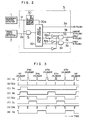
- a reference position detector l and crank angle detector 2 produce a reference position signal la and crank angle signal 2a, respectively.
- a cylinder identifying circuit 3 receives these output signals to identify cylinders, and produces a reference cylinder signal 3a, 4the cylinder signal 3b, 2/5th (2nd or 5th) cylinder signal 3c and 3/6th (3rd or 6th) cylinder signal 3d.
- the reference position signal la is a pulse signal rising at a certain angle (e.g., ll0°) before the dead point of each cylinder.
- the crank angle signal 2a is a pulse train, each pulse being generated at a certain rotational angle of the engine (e.g., one pulse per 2°-rotation, or generation of l80 pulses in one engine revolution).
- the reference position detector l is designed to produce the reference position signal la which has a different pulse width for each cylinder.
- a signal la for the first cylinder has a duration in which l6 pulses of the crank angle signal 2a are included
- a signal la for the second and fifth cylinders has a duration equivalent to 8 pulses of the signal 2a
- a signal la for the third and sixth cylinders has a duration equivalent to 4 pulses
- a signal la for the fourth cylinder has a duration equivalent to l2 pulses.
- the reference position signal la is taken AND with the crank angle signal 2a by an AND gate 3l, and its output is fed to a crank angle pulse counter 3l, which counts the number of pulses of the crank angle signal 2a included in the pulse width of the reference position signal la.
- the counter 32 produces a reference cylinder signal 3a for the first cylinder upon counting l6 pulses, and produces a 4th cylinder signal 3b for the fourth cylinder upon detection of l2 pulses.
- the counter 32 produces an 8-pulse signal 32a for the second and fifth cylinders, and produces 4- pulse signal for the third and sixth cylinders.
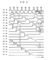
- the counter 32 is reset to the initial state in response to the generation of the next reference signal la, in such a manner that a pulse-rise detecting circuit 30 produces a narrow (e.g., 2 ⁇ s) clear signal 30a at the rising edge of the reference position signal la, as shown in Fig. 3, and this signal clears the crank angle pulse counter 32.
- the above circuit arrangement is intended to identify each cylinder by counting the number of pulses of the crank angle signal 2a in the duration of the reference position signal la.
- the 8-pulse signal 32a and 4-pulse signal 32b are each created in periods for multiple cylinders, and therefore signals at irrelevant cyli nders must be masked off.
- An AND gate 33 is used to take AND for the inverted output of the 4th cylinder signal 3b, the inverted output of the reference position signal la and the 8-pulse signal 32a so that the 8-pulse signal is reformed to the 2/5th cylinder signal 3c.
- an AND gate 34 takes AND for the 4-pulse signal 32b and the inverted outputs of the 8-pulse signal 32a and reference position signal la.
- the above circuit arrangement provides the signals for identifying cylinders.
- the reference cylinder signal 3a detected as described above is fed to a reference cylinder signal distributing circuit 5 in Fig. l, in which the signal is shifted successively by being triggered at the falling edge of an ignition signal 4a provided by an arithmetic unit 4 including a CPU, which receives the reference position signal la and crank angle signal 2a to calculate the ignition signal 4a.
- the reference cylinder signal distributing circuit 5 provides a lst cylinder ignition position signal 5a, 2nd cylinder ignition position signal 5b, 3rd cylinder ignition position signal 5c, 4th cylinder ignition position signal 5d, fifth cylinder ignition position signal 5e, and 6th cylinder ignition position signal 5f, in accordance with the ignition sequence of each cylinder.
- the ignition signal 4a is distributed to the cylinders by being simply taken AND with the cylinder ignition position signals 5a-5f.
- the reference cylinder signal distributing circuit 5 will erroneously respond to the noise and will be clocked to shift the reference position signal.
- the noise causes, at its timing, the 2nd cylinder ignition position signal 5b to go from high to low and, at the same time, the 3rd cylinder ignition position signal 5c to go high at the time point indicated by B.
- the generation of this improper pulse is the result of logical-product between the signals 5c and 4a, and such an event occuring in the suction stroke of a cylinder can ultimately damage the engine.
- the logical-product operations between the ignition signal 4a and the lst-6th cylinder ignition position signals 5a-5f further involve the cylinder signals 3b-3d by means of AND gates 6 through ll as shown in Fig. l, thereby immunizing the system from noises.
- the 3rd cylinder AND gate 8 takes AND for the 3rd cylinder ignition position signal 5c, the ignition signal 4a and the 3/6th cylinder ignition signal 24a derived from the 3/6th cylinder signal 3d through an OR gate 24, resulting in a low output as shown by D in Fig.
- the output signals 6a-lla of the AND gates 6-ll are delivered to the respective ignition circuits l2 through l7, each of which includes an ignition coil, a primary voltage switching device connected to the coil, and an ignition plug.
- the lst cylinder AND gate 6 takes AND for the lst cylinder ignition position signal 5a, the l/4th cylinder ignition signal 24a and the ignition signal 4a to produce the lst cylinder ignition signal 6a.
- the ignition signals for the remaining cylinders are produced in the same manner.
- a flip-flop 2l is provided for the purpose of preventing the l-6th cylinder ignition signals 6a-lla from being narrowed in their pulse width when the ignition signal 4a overlaps with the reference position signal la. It eventually prevents insufficient sparking caused by a decreased current supplied to the ignition coil when the ignition signal would be come narrower as the engine speed increases. This is the case shown in the timing chart of Fig.
- the signal overlap is detected to quit the AND operations between the ignition signal 4a and cylinder signals 3b-3d using the AND gate 20, flip-flop 2l and OR gates 22-24.
- the reference position signal la is taken AND with the ignition signal 4a by the AND gate 20 to detect the signal overlapping.
- the overlap signal 20a produced by the AND gate 20 triggers at its rising edge the flip-flop 2l, which then turns the output to high.
- the output signal of the flip-flop 2l is taken OR with the cylinder signals 3b-3d by the OR gates 22-24 to bring the cylinder ignition signals 22a-24a to high, whereby the ignition signals 6a-lla are prevented from being narrowed.
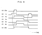
- Fig. 6 shows the second embodiment of this invention, in which common reference symbols are used for the components identical to those shown in Fig. l.
- the second and fifth cylinders are operated by the same 8-pulse signal without the distinction between the cylinders, and this relation is also the case of the third and sixth cylinders.
- This is based on the reason that if one of each cylinder pair is in the suction stroke, for example, the other cylinder is naturally in the exhaust stroke, and their distinction is practically unnecessary.
- it if it is intended to avoid the possibility of a backfire caused by the ignition in the exhaust stroke, it can be accomplished by providing a distinct pulse width for each of six cylinders.
- the circuit arrangement shown in Fig. 6 operates in principally the same manner as the operation of the foregoing embodiment, except that distinct cylinder signals 3A through 3F for identifying each cylinder are generated in this case, thereby providing the noise immunity for the ignition system.
Landscapes
- Engineering & Computer Science (AREA)
- Chemical & Material Sciences (AREA)
- Combustion & Propulsion (AREA)
- Mechanical Engineering (AREA)
- General Engineering & Computer Science (AREA)
- Ignition Installations For Internal Combustion Engines (AREA)
- Combined Controls Of Internal Combustion Engines (AREA)
- Electrical Control Of Ignition Timing (AREA)
Applications Claiming Priority (2)
| Application Number | Priority Date | Filing Date | Title |
|---|---|---|---|
| JP105548/86 | 1986-05-08 | ||
| JP61105548A JPH0639947B2 (ja) | 1986-05-08 | 1986-05-08 | 低圧電子配電点火装置 |
Publications (3)
| Publication Number | Publication Date |
|---|---|
| EP0244830A2 true EP0244830A2 (de) | 1987-11-11 |
| EP0244830A3 EP0244830A3 (en) | 1988-03-30 |
| EP0244830B1 EP0244830B1 (de) | 1992-07-29 |
Family
ID=14410627
Family Applications (1)
| Application Number | Title | Priority Date | Filing Date |
|---|---|---|---|
| EP87106513A Expired - Lifetime EP0244830B1 (de) | 1986-05-08 | 1987-05-06 | Elektronischer Zündverteiler für eine Fahrzeugmaschine |
Country Status (5)
| Country | Link |
|---|---|
| US (1) | US4726347A (de) |
| EP (1) | EP0244830B1 (de) |
| JP (1) | JPH0639947B2 (de) |
| KR (1) | KR870011369A (de) |
| DE (1) | DE3780694T2 (de) |
Cited By (2)
| Publication number | Priority date | Publication date | Assignee | Title |
|---|---|---|---|---|
| DE4007394A1 (de) * | 1989-03-08 | 1990-09-13 | Mitsubishi Electric Corp | Zuendsteuervorrichtung fuer einen verbrennungsmotor mit vielen zylindern |
| WO1996003580A1 (en) * | 1994-07-28 | 1996-02-08 | United Technologies Corporation | Electronic ignition system with pre-ignition prevention apparatus and method |
Families Citing this family (7)
| Publication number | Priority date | Publication date | Assignee | Title |
|---|---|---|---|---|
| KR910010035B1 (ko) * | 1987-05-14 | 1991-12-10 | 미쓰비시전기주식회사 | 점화시기 제어장치 |
| JPH01305161A (ja) * | 1988-06-03 | 1989-12-08 | Mitsubishi Electric Corp | エンジン用点火信号分配回路 |
| US4841932A (en) * | 1988-07-19 | 1989-06-27 | Delco Electronics Corporation | Spark timing control |
| US5027785A (en) * | 1990-04-19 | 1991-07-02 | Motorola, Inc. | Simplified ignition system for multi-cylinder engines |
| JP2569212B2 (ja) * | 1990-08-31 | 1997-01-08 | 三菱電機株式会社 | 内燃機関点火制御方法及び装置 |
| JP2573444B2 (ja) * | 1991-09-26 | 1997-01-22 | 株式会社日立製作所 | 内燃機関用点火装置 |
| GB9309527D0 (en) * | 1993-05-08 | 1993-06-23 | Lucas Ind Plc | Processing circuit |
Family Cites Families (9)
| Publication number | Priority date | Publication date | Assignee | Title |
|---|---|---|---|---|
| FR1596981A (de) * | 1968-12-20 | 1970-06-22 | ||
| US3757755A (en) * | 1971-10-14 | 1973-09-11 | Inst Gas Technology | Engine control apparatus |
| FR2374528A1 (fr) * | 1976-12-17 | 1978-07-13 | Cii | Systeme d'allumage electronique et moteur a combustion interne equipe d'un tel systeme |
| JPS53143834A (en) * | 1977-05-19 | 1978-12-14 | Mitsubishi Electric Corp | Igniter for multicylinder engine |
| JPS5928751B2 (ja) * | 1979-02-07 | 1984-07-16 | 三菱電機株式会社 | 内燃機関点火装置 |
| AT384862B (de) * | 1979-10-01 | 1988-01-25 | Jenbacher Werke Ag | Zuendeinrichtung fuer mehrzylindrige brennkraftmaschinen |
| JPS6035161A (ja) * | 1983-08-05 | 1985-02-22 | Fujitsu Ten Ltd | 燃料噴射制御装置用分配器 |
| US4649881A (en) * | 1983-08-17 | 1987-03-17 | Electromotive, Inc. | Precision distributorless ignition control system for internal combustion engines |
| JPS6073059A (ja) * | 1983-09-28 | 1985-04-25 | Mitsubishi Electric Corp | 内燃機関点火装置 |
-
1986
- 1986-05-08 JP JP61105548A patent/JPH0639947B2/ja not_active Expired - Fee Related
-
1987
- 1987-05-05 US US07/046,159 patent/US4726347A/en not_active Expired - Lifetime
- 1987-05-06 DE DE8787106513T patent/DE3780694T2/de not_active Expired - Fee Related
- 1987-05-06 KR KR870004398A patent/KR870011369A/ko not_active Withdrawn
- 1987-05-06 EP EP87106513A patent/EP0244830B1/de not_active Expired - Lifetime
Cited By (3)
| Publication number | Priority date | Publication date | Assignee | Title |
|---|---|---|---|---|
| DE4007394A1 (de) * | 1989-03-08 | 1990-09-13 | Mitsubishi Electric Corp | Zuendsteuervorrichtung fuer einen verbrennungsmotor mit vielen zylindern |
| WO1996003580A1 (en) * | 1994-07-28 | 1996-02-08 | United Technologies Corporation | Electronic ignition system with pre-ignition prevention apparatus and method |
| US5619968A (en) * | 1994-07-28 | 1997-04-15 | United Technologies Corporation | Electronic ignition system with pre-ignition prevention apparatus and method |
Also Published As
| Publication number | Publication date |
|---|---|
| US4726347A (en) | 1988-02-23 |
| EP0244830B1 (de) | 1992-07-29 |
| DE3780694T2 (de) | 1993-03-11 |
| EP0244830A3 (en) | 1988-03-30 |
| JPS62261673A (ja) | 1987-11-13 |
| DE3780694D1 (de) | 1992-09-03 |
| KR870011369A (ko) | 1987-12-23 |
| JPH0639947B2 (ja) | 1994-05-25 |
Similar Documents
| Publication | Publication Date | Title |
|---|---|---|
| EP0183771B1 (de) | Kontrollschaltung für referenzpulsierung anpassbar für motorenregelung | |
| US4797827A (en) | Angular position detector | |
| US4378004A (en) | Engine control system with cylinder identification apparatus | |
| US4941445A (en) | Electronic position sensor assembly and engine control system | |
| US4783627A (en) | Apparatus for detecting the rotational position of the crankshaft of an internal combustion engine | |
| EP0181379B1 (de) | Pulsierungsdetektor für fehlende oder zusätliche pulsierungen | |
| EP0244830A2 (de) | Elektronischer Zündverteiler für eine Fahrzeugmaschine | |
| US4457286A (en) | Engine ignition system | |
| US4711227A (en) | Apparatus and method for electronic ignition control | |
| DE19648951C2 (de) | Fehlzündungserfasserungsvorrichtung für einen Verbrennungsmotor | |
| KR0133939B1 (ko) | 고장시의 백업기능을 가지는 엔진의 점화타이밍 제어시스템 | |
| DE10233416B4 (de) | Zündsystem mit einem Permanentmagnet-Generator | |
| EP0375635B1 (de) | Verfahren und Vorrichtung zur Zündsteuerung bei inneren Brennkraftmaschinen, insbesondere bei Maschinen mit einer Zündspule pro Zylinder | |
| EP0624723B1 (de) | Signalverarbeitungsschaltung zur Verwendung in einem Steuersystem für einen Verbrennungsmotor | |
| EP0879956B1 (de) | Elektronischer Winkelgeber mit Steuerungssystem | |
| JP2590147B2 (ja) | エンジン制御装置 | |
| DE3917580C2 (de) | ||
| US5213079A (en) | Ignition timing control apparatus | |
| JP3329639B2 (ja) | 点火制御バックアップ装置 | |
| JPS62247179A (ja) | エンジン点火装置 | |
| KR0168081B1 (ko) | 내연기관의 기통판별 방법 | |
| JPH04303155A (ja) | 内燃機関のクランク角認識装置のノイズによる誤動作防止方法 | |
| JPH0527283U (ja) | 気筒別点火装置 | |
| JPH044466B2 (de) | ||
| JPH0552172A (ja) | 内燃機関の制御装置 |
Legal Events
| Date | Code | Title | Description |
|---|---|---|---|
| PUAI | Public reference made under article 153(3) epc to a published international application that has entered the european phase |
Free format text: ORIGINAL CODE: 0009012 |
|
| AK | Designated contracting states |
Kind code of ref document: A2 Designated state(s): DE GB |
|
| PUAL | Search report despatched |
Free format text: ORIGINAL CODE: 0009013 |
|
| AK | Designated contracting states |
Kind code of ref document: A3 Designated state(s): DE GB |
|
| 17P | Request for examination filed |
Effective date: 19880405 |
|
| 17Q | First examination report despatched |
Effective date: 19890915 |
|
| GRAA | (expected) grant |
Free format text: ORIGINAL CODE: 0009210 |
|
| AK | Designated contracting states |
Kind code of ref document: B1 Designated state(s): DE GB |
|
| REF | Corresponds to: |
Ref document number: 3780694 Country of ref document: DE Date of ref document: 19920903 |
|
| PLBE | No opposition filed within time limit |
Free format text: ORIGINAL CODE: 0009261 |
|
| STAA | Information on the status of an ep patent application or granted ep patent |
Free format text: STATUS: NO OPPOSITION FILED WITHIN TIME LIMIT |
|
| 26N | No opposition filed | ||
| REG | Reference to a national code |
Ref country code: GB Ref legal event code: IF02 |
|
| PGFP | Annual fee paid to national office [announced via postgrant information from national office to epo] |
Ref country code: GB Payment date: 20030425 Year of fee payment: 17 |
|
| PGFP | Annual fee paid to national office [announced via postgrant information from national office to epo] |
Ref country code: DE Payment date: 20030605 Year of fee payment: 17 |
|
| PG25 | Lapsed in a contracting state [announced via postgrant information from national office to epo] |
Ref country code: GB Free format text: LAPSE BECAUSE OF NON-PAYMENT OF DUE FEES Effective date: 20040506 |
|
| PG25 | Lapsed in a contracting state [announced via postgrant information from national office to epo] |
Ref country code: DE Free format text: LAPSE BECAUSE OF NON-PAYMENT OF DUE FEES Effective date: 20041201 |
|
| GBPC | Gb: european patent ceased through non-payment of renewal fee |
Effective date: 20040506 |