EP0243675A1 - Méthode pour l'amortissement de pulsation par compresseurs à piston - Google Patents
Méthode pour l'amortissement de pulsation par compresseurs à piston Download PDFInfo
- Publication number
- EP0243675A1 EP0243675A1 EP87104358A EP87104358A EP0243675A1 EP 0243675 A1 EP0243675 A1 EP 0243675A1 EP 87104358 A EP87104358 A EP 87104358A EP 87104358 A EP87104358 A EP 87104358A EP 0243675 A1 EP0243675 A1 EP 0243675A1
- Authority
- EP
- European Patent Office
- Prior art keywords
- section
- throttle
- cross
- pressure
- piston compressors
- Prior art date
- Legal status (The legal status is an assumption and is not a legal conclusion. Google has not performed a legal analysis and makes no representation as to the accuracy of the status listed.)
- Granted
Links
- 238000000034 method Methods 0.000 title claims description 9
- 230000010349 pulsation Effects 0.000 title claims description 8
- 238000013016 damping Methods 0.000 title claims description 7
- 238000011144 upstream manufacturing Methods 0.000 claims 1
- 230000006835 compression Effects 0.000 abstract 1
- 238000007906 compression Methods 0.000 abstract 1
- 230000000694 effects Effects 0.000 description 3
- 238000010586 diagram Methods 0.000 description 1
Images

Classifications
-
- F—MECHANICAL ENGINEERING; LIGHTING; HEATING; WEAPONS; BLASTING
- F04—POSITIVE - DISPLACEMENT MACHINES FOR LIQUIDS; PUMPS FOR LIQUIDS OR ELASTIC FLUIDS
- F04B—POSITIVE-DISPLACEMENT MACHINES FOR LIQUIDS; PUMPS
- F04B11/00—Equalisation of pulses, e.g. by use of air vessels; Counteracting cavitation
- F04B11/0008—Equalisation of pulses, e.g. by use of air vessels; Counteracting cavitation using accumulators
-
- F—MECHANICAL ENGINEERING; LIGHTING; HEATING; WEAPONS; BLASTING
- F04—POSITIVE - DISPLACEMENT MACHINES FOR LIQUIDS; PUMPS FOR LIQUIDS OR ELASTIC FLUIDS
- F04B—POSITIVE-DISPLACEMENT MACHINES FOR LIQUIDS; PUMPS
- F04B11/00—Equalisation of pulses, e.g. by use of air vessels; Counteracting cavitation
- F04B11/0091—Equalisation of pulses, e.g. by use of air vessels; Counteracting cavitation using a special shape of fluid pass, e.g. throttles, ducts
-
- F—MECHANICAL ENGINEERING; LIGHTING; HEATING; WEAPONS; BLASTING
- F16—ENGINEERING ELEMENTS AND UNITS; GENERAL MEASURES FOR PRODUCING AND MAINTAINING EFFECTIVE FUNCTIONING OF MACHINES OR INSTALLATIONS; THERMAL INSULATION IN GENERAL
- F16L—PIPES; JOINTS OR FITTINGS FOR PIPES; SUPPORTS FOR PIPES, CABLES OR PROTECTIVE TUBING; MEANS FOR THERMAL INSULATION IN GENERAL
- F16L55/00—Devices or appurtenances for use in, or in connection with, pipes or pipe systems
- F16L55/02—Energy absorbers; Noise absorbers
- F16L55/027—Throttle passages
-
- F—MECHANICAL ENGINEERING; LIGHTING; HEATING; WEAPONS; BLASTING
- F17—STORING OR DISTRIBUTING GASES OR LIQUIDS
- F17D—PIPE-LINE SYSTEMS; PIPE-LINES
- F17D1/00—Pipe-line systems
- F17D1/20—Arrangements or systems of devices for influencing or altering dynamic characteristics of the systems, e.g. for damping pulsations caused by opening or closing of valves
Definitions
- the invention relates to a method for damping the pulsation in piston compressors with the features of the preamble of claim 1.
- buffer containers which have a sufficiently large volume and are arranged as close as possible to the cylinder of the piston compressor. Unavoidable pressure fluctuations due to resonances are dampened by throttling devices in the suction and / or pressure line.
- the effect of the throttle device is based on the generation of a pressure loss, the amount of which depends on the flow rate of the conveyed medium. If the delivery rate of the piston compressor is reduced, the damping effect diminishes because of the lower flow speed.
- the free cross section of the throttle device must be designed for the partial load in this case, since the system is particularly at risk in this load range. However, this has the consequence that the pressure loss at full load is much higher than required and the efficiency is thereby reduced.
- the invention has for its object to dampen the pulsation in piston compressors so that the pulsation does not exceed a predetermined value with the lowest possible pressure loss.
- the damping effect can be adapted to the prevailing conditions.
- the damping can thus be optimally adjusted, the pressure losses resulting from the reduction in cross section not exceeding the value that is just necessary.
- a ZyLinder 1 of a piston compressor encloses an axially displaceable piston 2.
- the cylinder 1 is provided with an intake port 3 and an outlet port 4 connected to a suction line.
- a throttle 7 is inserted in the pressure line 6.
- the cross section of the DrosseL 7 can be changed.
- the throttle 7 is provided with a control drive 8.
- the DrosseL 7 can also be arranged on the suction side of the piston compressor. Instead of one throttle, several can also be provided.
- the actuator 8 is connected to a controller 9.
- a pressure measuring device 10 is arranged in the pressure line 6 behind the throttle 7.
- a measuring line 11 is led from the pressure measuring device 10 to the controller 9.
- a limit value 12 is entered in the controller 9, which indicates the value of the pressure fluctuation which is still considered permissible.
- the measured value supplied by the pressure measuring device 10 is compared in the controller 9 with the previously entered limit value 12. If the measured pressure fluctuation is greater than the limit value, the controller 9 uses the actuator 8 to reduce the cross section of the throttle until the limit value is no longer exceeded. If the measured pressure fluctuation is smaller, the cross-section is increased and the pressure loss is reduced until the limit value is just not exceeded.
- the pressure fluctuation is not measured, and the controller is replaced by a controller 13.
- the controller 13 receives a signal 14 from the piston compressor about the level of the flow rate set. Based on this signal 14, the actuator 8 changes the cross section of the throttle 7 via the dependency entered in the controller 13.
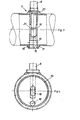
- 3 and 4 consists of a disk 15 which is screwed between the flange 16 of the buffer container 5 and the flange 17 of the pressure line 6.
- the disc 15 has two axial openings 18, 19.
- the cross section of the opening 18 is always open. This cross-section is dimensioned such that the pressure build-up occurring does not endanger the cylinder 1 or the pressure line 6 at maximum flow.
- the opening 18 thus serves for security in the event of a possible failure of the regulation or the control.
- the cross section of the opening 19 can be changed.
- a pin 20 is used, which is guided in a radial bore 21 of the disk 15, which penetrates the opening 19.
- Actuator 8 which is only indicated in FIGS. 3 and 4, engages pin 20.
- Actuators of this type which can act mechanically, pneumatically, hydraulically or electrically, are known per se, so that a more detailed explanation can be dispensed with.
Landscapes
- Engineering & Computer Science (AREA)
- General Engineering & Computer Science (AREA)
- Mechanical Engineering (AREA)
- Compressor (AREA)
- Control Of Positive-Displacement Pumps (AREA)
- Compressors, Vaccum Pumps And Other Relevant Systems (AREA)
- Pipe Accessories (AREA)
- Control Of Positive-Displacement Air Blowers (AREA)
Priority Applications (1)
| Application Number | Priority Date | Filing Date | Title |
|---|---|---|---|
| AT87104358T ATE44600T1 (de) | 1986-05-02 | 1987-03-24 | Verfahren zur pulsationsdaempfung bei kolbenkompressoren. |
Applications Claiming Priority (2)
| Application Number | Priority Date | Filing Date | Title |
|---|---|---|---|
| DE19863614930 DE3614930A1 (de) | 1986-05-02 | 1986-05-02 | Vorrichtung und verfahren zur pulsationsdaempfung bei kolbenkompressoren |
| DE3614930 | 1986-05-02 |
Publications (2)
| Publication Number | Publication Date |
|---|---|
| EP0243675A1 true EP0243675A1 (fr) | 1987-11-04 |
| EP0243675B1 EP0243675B1 (fr) | 1989-07-12 |
Family
ID=6300054
Family Applications (1)
| Application Number | Title | Priority Date | Filing Date |
|---|---|---|---|
| EP87104358A Expired EP0243675B1 (fr) | 1986-05-02 | 1987-03-24 | Méthode pour l'amortissement de pulsation par compresseurs à piston |
Country Status (6)
| Country | Link |
|---|---|
| US (1) | US4801245A (fr) |
| EP (1) | EP0243675B1 (fr) |
| AT (1) | ATE44600T1 (fr) |
| DE (2) | DE3614930A1 (fr) |
| ES (1) | ES2009811B3 (fr) |
| GR (1) | GR3000176T3 (fr) |
Cited By (2)
| Publication number | Priority date | Publication date | Assignee | Title |
|---|---|---|---|---|
| WO1991009214A1 (fr) * | 1989-12-12 | 1991-06-27 | Group Lotus Plc | Attenuation des fluctuations de pression dynamique dans les conduits |
| CN113464845A (zh) * | 2021-07-13 | 2021-10-01 | 清华大学 | 一种气路组件和喘振抑制系统 |
Families Citing this family (12)
| Publication number | Priority date | Publication date | Assignee | Title |
|---|---|---|---|---|
| US5168703A (en) * | 1989-07-18 | 1992-12-08 | Jaromir Tobias | Continuously active pressure accumulator power transfer system |
| US5062498A (en) * | 1989-07-18 | 1991-11-05 | Jaromir Tobias | Hydrostatic power transfer system with isolating accumulator |
| US5310017A (en) * | 1989-07-18 | 1994-05-10 | Jaromir Tobias | Vibration isolation support mounting system |
| US5101929A (en) * | 1989-07-18 | 1992-04-07 | Jaromir Tobias | Vibration isolation support mounting system |
| JP2649091B2 (ja) * | 1989-09-05 | 1997-09-03 | 株式会社 豊田中央研究所 | 高圧液体供給装置 |
| US5193885A (en) * | 1990-05-01 | 1993-03-16 | Jidosha Kiki Co., Ltd. | Hydraulic pressure booster system |
| US5389173A (en) * | 1992-12-02 | 1995-02-14 | Paper Converting Machine Company | Apparatus and process for making disposable diaper type products |
| US5560205A (en) * | 1994-12-21 | 1996-10-01 | Caterpillar Inc. | Attenuation of fluid borne noise |
| US6070408A (en) * | 1997-11-25 | 2000-06-06 | Caterpillar Inc. | Hydraulic apparatus with improved accumulator for reduced pressure pulsation and method of operating the same |
| DE102005036921A1 (de) * | 2005-08-05 | 2007-02-08 | Bayerische Motoren Werke Ag | Pulsationsminderer für hydraulische Systeme |
| JP7226175B2 (ja) * | 2019-07-31 | 2023-02-21 | トヨタ自動車株式会社 | 配管及びブレーキシステム |
| CN110939559B (zh) * | 2019-11-08 | 2021-09-28 | 陕西航天动力高科技股份有限公司 | 一种隔膜泵缓冲系统 |
Citations (1)
| Publication number | Priority date | Publication date | Assignee | Title |
|---|---|---|---|---|
| DE3036821A1 (de) * | 1979-10-01 | 1981-04-16 | Grove Valve and Regulator Co., Oakland, Calif. | Vorrichtung zum feststellen von druckaenderungen bzw. druckaenderungsgeschwindigekiten |
Family Cites Families (10)
| Publication number | Priority date | Publication date | Assignee | Title |
|---|---|---|---|---|
| US17726A (en) * | 1857-07-07 | Air-chamber to effect uniformity of flow of water | ||
| FR429784A (fr) * | 1911-05-17 | 1911-09-30 | Theodore Lafitte | Limitateur de pression hydraulique |
| US1946319A (en) * | 1931-11-05 | 1934-02-06 | Kent Ltd G | Variable orifice for measuring the flow of fluids |
| US3027902A (en) * | 1960-03-31 | 1962-04-03 | Specialties Dev Corp | Fluid motor throttle valve means responsive to motor exhaust pressure |
| BE757640A (fr) * | 1969-10-16 | 1971-04-16 | Borg Warner | Systemes hydrauliques, notamment pour la regulation d'une pompea debit variable |
| DE2753805A1 (de) * | 1977-12-02 | 1979-06-07 | Knorr Bremse Gmbh | Druckluftversorgungseinrichtung fuer druckluftanlagen, insbesondere von schienenfahrzeugen |
| FR2432160A1 (fr) * | 1978-07-27 | 1980-02-22 | Alsthom Atlantique | Dispositif de mesure du debit d'une canalisation |
| JPS57177485A (en) * | 1981-04-22 | 1982-11-01 | Sharp Kk | Ripple removing device in liquid feeder |
| US4558994A (en) * | 1984-07-02 | 1985-12-17 | Parker-Hannifin Corporation | Dual stage air compressor |
| US4632358A (en) * | 1984-07-17 | 1986-12-30 | Eaton Corporation | Automotive air conditioning system including electrically operated expansion valve |
-
1986
- 1986-05-02 DE DE19863614930 patent/DE3614930A1/de not_active Withdrawn
-
1987
- 1987-03-24 AT AT87104358T patent/ATE44600T1/de not_active IP Right Cessation
- 1987-03-24 DE DE8787104358T patent/DE3760315D1/de not_active Expired
- 1987-03-24 ES ES87104358T patent/ES2009811B3/es not_active Expired
- 1987-03-24 EP EP87104358A patent/EP0243675B1/fr not_active Expired
-
1988
- 1988-04-08 US US07/183,259 patent/US4801245A/en not_active Expired - Fee Related
-
1989
- 1989-10-06 GR GR89400194T patent/GR3000176T3/el unknown
Patent Citations (1)
| Publication number | Priority date | Publication date | Assignee | Title |
|---|---|---|---|---|
| DE3036821A1 (de) * | 1979-10-01 | 1981-04-16 | Grove Valve and Regulator Co., Oakland, Calif. | Vorrichtung zum feststellen von druckaenderungen bzw. druckaenderungsgeschwindigekiten |
Cited By (2)
| Publication number | Priority date | Publication date | Assignee | Title |
|---|---|---|---|---|
| WO1991009214A1 (fr) * | 1989-12-12 | 1991-06-27 | Group Lotus Plc | Attenuation des fluctuations de pression dynamique dans les conduits |
| CN113464845A (zh) * | 2021-07-13 | 2021-10-01 | 清华大学 | 一种气路组件和喘振抑制系统 |
Also Published As
| Publication number | Publication date |
|---|---|
| DE3760315D1 (en) | 1989-08-17 |
| ES2009811B3 (es) | 1989-10-16 |
| GR3000176T3 (en) | 1990-12-31 |
| DE3614930A1 (de) | 1987-11-05 |
| ATE44600T1 (de) | 1989-07-15 |
| US4801245A (en) | 1989-01-31 |
| EP0243675B1 (fr) | 1989-07-12 |
Similar Documents
| Publication | Publication Date | Title |
|---|---|---|
| EP0243675B1 (fr) | Méthode pour l'amortissement de pulsation par compresseurs à piston | |
| EP0009564A1 (fr) | Cycle de graissage pour moteur à combustion interne | |
| EP0335105B1 (fr) | Procédé pour éviter le pompage d'un compresseur centrifuge par le contrôle d'échappement | |
| DE2845955A1 (de) | Verfahren zur entfernung von oeldaempfen aus dem gehaeuse einer brennkraftmaschine und vorrichtung zur durchfuehrung dieses verfahrens | |
| DE3639245A1 (de) | In form einer schleife angeordnetes einspritz-zirkulations-system | |
| DE3340401A1 (de) | Einrichtung zum stufenweisen druckabbau bei der entspannung von insbesondere heissen gasen | |
| DE1107887B (de) | Regler zur Pumpverhuetung bei Stroemungsverdichtern | |
| DE4316202C2 (de) | Verfahren zur Überwachung der Pumpgrenze eines Turboverdichters mit Vorleitapparat und Nachleitapparat | |
| DE3039613C2 (de) | System zum Regeln der Leerlaufdrehzahl von Ottomotoren | |
| DE19600377B4 (de) | Druckgasanlage mit einem Gastrockner | |
| DE3743645A1 (de) | Kraftstoffeinspritzsystem mit druckakkumulation | |
| DE3528781C2 (fr) | ||
| DE19956224B4 (de) | Verdichtersteuerung | |
| DE648910C (de) | Kreiselpumpenanlage | |
| DE10248625A1 (de) | Vorrichtung zur Drosselung der Flüssigkeitsmenge, die von einer Förderpumpe angesaugt wird | |
| EP1198674B1 (fr) | Procede et dispositif pour reguler la pression dans une conduite d'alimentation sortant d'une pompe centrifuge | |
| DE2929444C2 (de) | Einrichtung zur Regulierung der Zusammensetzung einer zu verbrennenden Emulsion | |
| DE2206452A1 (de) | Saugeinheit für eine Durchflußleistung mit konstantem Volumen | |
| DE1428066A1 (de) | Grenzmengenregelung an Turboverdichtern | |
| AT405439B (de) | Gasarmatur | |
| DE1601634A1 (de) | Vorrichtung zum schutz des verdichters eines gasturbinentriebwerks gegen pumpwirkungen | |
| DE4118644C2 (fr) | ||
| DE3116710C2 (de) | Verfahren zur Regelung der Kühldampfmenge für den Niederdruckteil einer Entnahme-Kondensations-Turbine | |
| DE3341433A1 (de) | Absperrventil | |
| AT254378B (de) | Selbsttätige Regelvorrichtung für Verdichter mit hoher Durchsatzleistung |
Legal Events
| Date | Code | Title | Description |
|---|---|---|---|
| PUAI | Public reference made under article 153(3) epc to a published international application that has entered the european phase |
Free format text: ORIGINAL CODE: 0009012 |
|
| AK | Designated contracting states |
Kind code of ref document: A1 Designated state(s): AT BE CH DE ES FR GB GR IT LI LU NL SE |
|
| 17P | Request for examination filed |
Effective date: 19871116 |
|
| 17Q | First examination report despatched |
Effective date: 19881221 |
|
| GRAA | (expected) grant |
Free format text: ORIGINAL CODE: 0009210 |
|
| AK | Designated contracting states |
Kind code of ref document: B1 Designated state(s): AT BE CH DE ES FR GB GR IT LI LU NL SE |
|
| REF | Corresponds to: |
Ref document number: 44600 Country of ref document: AT Date of ref document: 19890715 Kind code of ref document: T |
|
| REF | Corresponds to: |
Ref document number: 3760315 Country of ref document: DE Date of ref document: 19890817 |
|
| ET | Fr: translation filed | ||
| GBT | Gb: translation of ep patent filed (gb section 77(6)(a)/1977) | ||
| ITF | It: translation for a ep patent filed | ||
| PLBE | No opposition filed within time limit |
Free format text: ORIGINAL CODE: 0009261 |
|
| STAA | Information on the status of an ep patent application or granted ep patent |
Free format text: STATUS: NO OPPOSITION FILED WITHIN TIME LIMIT |
|
| REG | Reference to a national code |
Ref country code: GR Ref legal event code: FG4A Free format text: 3000176 |
|
| 26N | No opposition filed | ||
| PGFP | Annual fee paid to national office [announced via postgrant information from national office to epo] |
Ref country code: GR Payment date: 19910226 Year of fee payment: 5 |
|
| PGFP | Annual fee paid to national office [announced via postgrant information from national office to epo] |
Ref country code: LU Payment date: 19910228 Year of fee payment: 5 Ref country code: BE Payment date: 19910228 Year of fee payment: 5 |
|
| PGFP | Annual fee paid to national office [announced via postgrant information from national office to epo] |
Ref country code: SE Payment date: 19910313 Year of fee payment: 5 |
|
| PGFP | Annual fee paid to national office [announced via postgrant information from national office to epo] |
Ref country code: ES Payment date: 19910314 Year of fee payment: 5 |
|
| EPTA | Lu: last paid annual fee | ||
| PG25 | Lapsed in a contracting state [announced via postgrant information from national office to epo] |
Ref country code: LU Free format text: LAPSE BECAUSE OF NON-PAYMENT OF DUE FEES Effective date: 19920324 |
|
| PG25 | Lapsed in a contracting state [announced via postgrant information from national office to epo] |
Ref country code: SE Effective date: 19920325 Ref country code: ES Free format text: LAPSE BECAUSE OF NON-PAYMENT OF DUE FEES Effective date: 19920325 |
|
| PG25 | Lapsed in a contracting state [announced via postgrant information from national office to epo] |
Ref country code: BE Effective date: 19920331 |
|
| BERE | Be: lapsed |
Owner name: BORSIG G.M.B.H. Effective date: 19920331 |
|
| PG25 | Lapsed in a contracting state [announced via postgrant information from national office to epo] |
Ref country code: GR Free format text: THE PATENT HAS BEEN ANNULLED BY A DECISION OF A NATIONAL AUTHORITY Effective date: 19920930 |
|
| PGFP | Annual fee paid to national office [announced via postgrant information from national office to epo] |
Ref country code: GB Payment date: 19930302 Year of fee payment: 7 |
|
| PG25 | Lapsed in a contracting state [announced via postgrant information from national office to epo] |
Ref country code: GB Effective date: 19940324 |
|
| GBPC | Gb: european patent ceased through non-payment of renewal fee |
Effective date: 19940324 |
|
| REG | Reference to a national code |
Ref country code: GR Ref legal event code: MM2A Free format text: 3000176 |
|
| PGFP | Annual fee paid to national office [announced via postgrant information from national office to epo] |
Ref country code: FR Payment date: 19950117 Year of fee payment: 9 |
|
| PGFP | Annual fee paid to national office [announced via postgrant information from national office to epo] |
Ref country code: AT Payment date: 19950118 Year of fee payment: 9 |
|
| EUG | Se: european patent has lapsed |
Ref document number: 87104358.4 Effective date: 19921005 |
|
| PGFP | Annual fee paid to national office [announced via postgrant information from national office to epo] |
Ref country code: NL Payment date: 19950331 Year of fee payment: 9 |
|
| PG25 | Lapsed in a contracting state [announced via postgrant information from national office to epo] |
Ref country code: AT Effective date: 19960324 |
|
| PG25 | Lapsed in a contracting state [announced via postgrant information from national office to epo] |
Ref country code: NL Effective date: 19961001 |
|
| PG25 | Lapsed in a contracting state [announced via postgrant information from national office to epo] |
Ref country code: FR Effective date: 19961129 |
|
| NLV4 | Nl: lapsed or anulled due to non-payment of the annual fee |
Effective date: 19961001 |
|
| REG | Reference to a national code |
Ref country code: FR Ref legal event code: ST |
|
| REG | Reference to a national code |
Ref country code: CH Ref legal event code: PUE Owner name: BORSIG GMBH TRANSFER- GHH BORSIG TURBOMASCHINEN GM |
|
| REG | Reference to a national code |
Ref country code: ES Ref legal event code: FD2A Effective date: 19990301 |
|
| PGFP | Annual fee paid to national office [announced via postgrant information from national office to epo] |
Ref country code: CH Payment date: 20000221 Year of fee payment: 14 |
|
| PGFP | Annual fee paid to national office [announced via postgrant information from national office to epo] |
Ref country code: DE Payment date: 20000224 Year of fee payment: 14 |
|
| PG25 | Lapsed in a contracting state [announced via postgrant information from national office to epo] |
Ref country code: LI Free format text: LAPSE BECAUSE OF NON-PAYMENT OF DUE FEES Effective date: 20010331 Ref country code: CH Free format text: LAPSE BECAUSE OF NON-PAYMENT OF DUE FEES Effective date: 20010331 |
|
| REG | Reference to a national code |
Ref country code: CH Ref legal event code: PL |
|
| PG25 | Lapsed in a contracting state [announced via postgrant information from national office to epo] |
Ref country code: DE Free format text: LAPSE BECAUSE OF NON-PAYMENT OF DUE FEES Effective date: 20020101 |
|
| PG25 | Lapsed in a contracting state [announced via postgrant information from national office to epo] |
Ref country code: IT Free format text: LAPSE BECAUSE OF NON-PAYMENT OF DUE FEES;WARNING: LAPSES OF ITALIAN PATENTS WITH EFFECTIVE DATE BEFORE 2007 MAY HAVE OCCURRED AT ANY TIME BEFORE 2007. THE CORRECT EFFECTIVE DATE MAY BE DIFFERENT FROM THE ONE RECORDED. Effective date: 20050324 |