EP0243596B1 - Axialdrallregler für einen Abgasturbolader für Verbrennungsmotoren - Google Patents
Axialdrallregler für einen Abgasturbolader für Verbrennungsmotoren Download PDFInfo
- Publication number
- EP0243596B1 EP0243596B1 EP87102412A EP87102412A EP0243596B1 EP 0243596 B1 EP0243596 B1 EP 0243596B1 EP 87102412 A EP87102412 A EP 87102412A EP 87102412 A EP87102412 A EP 87102412A EP 0243596 B1 EP0243596 B1 EP 0243596B1
- Authority
- EP
- European Patent Office
- Prior art keywords
- section
- guide vanes
- drag regulator
- axial drag
- regulator according
- Prior art date
- Legal status (The legal status is an assumption and is not a legal conclusion. Google has not performed a legal analysis and makes no representation as to the accuracy of the status listed.)
- Expired - Lifetime
Links
- 238000002485 combustion reaction Methods 0.000 title claims abstract description 7
- 230000007704 transition Effects 0.000 claims description 3
- 238000005192 partition Methods 0.000 claims 1
- 230000033228 biological regulation Effects 0.000 description 3
- 239000000446 fuel Substances 0.000 description 3
- 230000002093 peripheral effect Effects 0.000 description 3
- 238000005086 pumping Methods 0.000 description 3
- 230000001133 acceleration Effects 0.000 description 2
- 238000006073 displacement reaction Methods 0.000 description 2
- 230000000694 effects Effects 0.000 description 2
- 238000004519 manufacturing process Methods 0.000 description 2
- 230000001960 triggered effect Effects 0.000 description 2
- 238000010276 construction Methods 0.000 description 1
- 230000001419 dependent effect Effects 0.000 description 1
- 238000010586 diagram Methods 0.000 description 1
- 230000007257 malfunction Effects 0.000 description 1
- 238000005096 rolling process Methods 0.000 description 1
- 238000000926 separation method Methods 0.000 description 1
- 239000007787 solid Substances 0.000 description 1
- 230000001629 suppression Effects 0.000 description 1
Images
Classifications
-
- F—MECHANICAL ENGINEERING; LIGHTING; HEATING; WEAPONS; BLASTING
- F04—POSITIVE - DISPLACEMENT MACHINES FOR LIQUIDS; PUMPS FOR LIQUIDS OR ELASTIC FLUIDS
- F04D—NON-POSITIVE-DISPLACEMENT PUMPS
- F04D29/00—Details, component parts, or accessories
- F04D29/40—Casings; Connections of working fluid
- F04D29/42—Casings; Connections of working fluid for radial or helico-centrifugal pumps
- F04D29/44—Fluid-guiding means, e.g. diffusers
- F04D29/46—Fluid-guiding means, e.g. diffusers adjustable
- F04D29/462—Fluid-guiding means, e.g. diffusers adjustable especially adapted for elastic fluid pumps
-
- F—MECHANICAL ENGINEERING; LIGHTING; HEATING; WEAPONS; BLASTING
- F04—POSITIVE - DISPLACEMENT MACHINES FOR LIQUIDS; PUMPS FOR LIQUIDS OR ELASTIC FLUIDS
- F04D—NON-POSITIVE-DISPLACEMENT PUMPS
- F04D29/00—Details, component parts, or accessories
- F04D29/40—Casings; Connections of working fluid
- F04D29/42—Casings; Connections of working fluid for radial or helico-centrifugal pumps
- F04D29/4206—Casings; Connections of working fluid for radial or helico-centrifugal pumps especially adapted for elastic fluid pumps
- F04D29/4213—Casings; Connections of working fluid for radial or helico-centrifugal pumps especially adapted for elastic fluid pumps suction ports
-
- F—MECHANICAL ENGINEERING; LIGHTING; HEATING; WEAPONS; BLASTING
- F05—INDEXING SCHEMES RELATING TO ENGINES OR PUMPS IN VARIOUS SUBCLASSES OF CLASSES F01-F04
- F05D—INDEXING SCHEME FOR ASPECTS RELATING TO NON-POSITIVE-DISPLACEMENT MACHINES OR ENGINES, GAS-TURBINES OR JET-PROPULSION PLANTS
- F05D2250/00—Geometry
- F05D2250/50—Inlet or outlet
- F05D2250/51—Inlet
Definitions
- the invention relates to an axial swirl controller for an exhaust gas turbocharger according to the preamble of claim 1.
- Exhaust gas turbochargers are used in internal combustion engines to increase power and torque with low fuel consumption. Since turbochargers with a radial compressor are not able to cover the entire operating range of the internal combustion engines due to their pressure-volume characteristics, operating conditions can occur on the one hand at low engine speed and at full load, which are to the left of the pumping or tear-off limit of the compressor map and on the other hand, at high engine speeds and full load operation, they are to the right of the stuffing limit of the compressor map. For this reason, it is customary to design turbochargers in such a way that the pumping or tear-off limit is not exceeded to the left at low engine speeds and at part-load or full-load operation.
- Bypass valves are known on the turbine side for controlling this operating behavior, e.g. through DE-A-14 26 076, with the help of which part of the exhaust gas flow can be passed around the turbine in order to avoid high boost pressures at full load and high speed. With this regulation, part of the exhaust gas energy is lost unused.
- turbine-side regulations for turbochargers only affect the output or the torque. They are suitable for adapting the instantaneous power requirement of the compressor to the requirements within the limits given by the available exhaust gas quantity and exhaust gas temperature. They change the mass flow, but not the compressor map. As a result, it is quite possible that the compressor operating point may move out of the area of good efficiency or even get into the pumping area.
- a compressor-side turbocharger control is also known from DE-A-14 26 076, wherein the volume flow can be reduced or even completely prevented by means of a throttle valve in the suction area. It may be desirable to prevent the volume flow in order to relieve the motor temporarily, e.g. When disengaging, ensure that the compressor no longer draws power and the turbocharger rotor does not drop too much in speed. With this compressor-side turbocharger control, however, it is not possible to change the usable map width.
- the flow channel in which the guide vanes of the axial guide apparatus are arranged, consists of two cylindrical jacket sections with only slightly different diameters and an intermediate ball section, in which the ball radius is larger than the radius of the larger cylindrical jacket section, i.e. the flow channel experiences an increase in diameter in the area of the guide vanes.
- This increase in diameter in the flow channel leads to a separation of the flow and to an increase in the vortex wake triggered by a speed jump on the guide vanes. Since the cylindrical casing section adjoining the spherical section on the compressor side has only an insignificantly smaller diameter than the first cylindrical casing section, rapid suppression of the disturbance of the flow before entering the compressor is not possible.
- an axial swirl controller is known in which guide vanes are used, the axis of rotation of which runs through the axis of symmetry of the guide vane surface, the axes of rotation being arranged inclined such that the front edge of the opened guide vanes is approximately along the radius of the inlet-side flow channel runs.
- the input-side flow channel is connected via a polygon housing to the output-side flow channel, the diameter of which is smaller than that of the input-side flow channel.
- a gear box is arranged in the center of the flow channel, in which the front ends of the axes of rotation are connected to one another via a bevel gear, in order to ensure the same positioning for all guide vanes during the adjustment.
- a radial compressor with an axial swirl regulator is known from DE-A-15 03 658, in which, after a conical inlet, the intake duct has a short cylinder section as seen in the flow direction, which section merges into a spherical section and a subsequent cylinder section with a smaller diameter.
- the axes of rotation of the guide vanes, the edges of which follow the spherical channel contour, are mounted in the plane of the transition from the first cylinder section to the spherical section.
- the invention has for its object to provide an axial swirl controller for a turbocharger, with which the sales area of the internal combustion engine is further expanded with the best efficiency and low fuel consumption can be.
- these optimal operating ranges should be reached quickly and economically, which means that extreme operating states and their sudden changes can also be operated economically.
- the usable control range must be so wide and the compressor map must be designed so that the respective operating point is in the range of the best efficiency and the surge limit does not affect the respective operating point due to the shifting of the characteristic field.
- the measures of the invention ensure that behind the pivotable guide vanes, the two-cylindrical section adjoining the spherical section has a substantially smaller radius, and thus the reduction in the cross section of the flow channel produces an accelerated nozzle flow, as a result of which the guide vanes malfunction, and in particular those caused by the boundary layer effect Triggered dimples are quickly suppressed and a healthy, even inflow to the compressor impeller is guaranteed.
- the surge limit is shifted so far to the left that the amount of charge air and the required charge air pressure, which are dependent on the engine load, the fuel requirement and the engine speed, are available even in extreme operating conditions and their sudden change , whereby the characteristic field is shifted so that the operating pressure is always to the right of the surge limit.
- Another embodiment of the invention is the subject of a subclaim.
- ratios of the diameters from the first cylinder section to the second cylinder section between 1.4 and 1.6 and preferably between 1.45 and 1.5 have proven to be particularly expedient, the measures of the invention also offering the possibility in the turbochargers used today in motor vehicle construction with very small compressor wheel diameters to ensure that optimal operating conditions are possible in the entire engine operating range.
- the invention provides measures that the diffuser can be assembled so that a perfect setting without jamming is possible, and that the fixation takes place only afterwards by a force-fitting screw connection.
- the shafts of the axes of rotation of the guide vanes are roller-mounted in the housing and carry the adjusting lever outside the housing, and that the guide vanes, the roller bearing and the adjusting lever are non-positively clamped.
- the free end of the adjusting lever carries a ball pin which is guided in a groove in the adjusting ring which is parallel to the loader axis, the adjusting ring being mounted concentrically to the loader axis on the outer circumference of the housing on a cylindrical annular surface.
- This bearing is preferably a needle bearing.
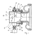
- the axial swirl regulator 1 shown in FIG. 1 and mounted on the volute of the compressor of a turbocharger for internal combustion engines consists of a housing 6, in the interior of which the flow channel runs, in which a diffuser 2 with adjustable guide vanes 5 is arranged.
- the flow channel has a first cylinder section 9, which extends in front of the guide device 2 and merges into a spherical section 10, the spherical radius of which is equal to the radius of the first cylindrical section 9. Closes the ball section 10 a second cylinder section 11, the diameter of which is substantially smaller than the first cylinder section 9 and into which the ball section merges with a part designed as a nozzle section 12.
- the guide device 2 consists of a ring of guide vanes 5 which extend over the cross section of the flow channel and essentially have a circular section of such shape and division that the guide vanes 5 cover the cross section of the flow channel almost completely when the guide device 2 is completely closed. 1, only one guide vane 5 is shown.
- the axis of rotation of the individual guide blades 5 runs in each case in the blade leading edge, so that the outwardly projecting shaft of the guide blades runs in the extension of the leading edge.
- the spherical section 10 which, as already mentioned, has a spherical radius corresponding to the radius of the first cylindrical section 9.
- the base of the guide vanes also runs in a circular arc with a radius that corresponds to the radius of the sphere, so that when the guide vanes are pivoted, there is a constant, uniform gap width for all angular positions and the rear edge of the guide vane follows the channel contour.
- the shaft of the guide vanes 5 is mounted in the housing 6 with a roller bearing 13 and carries an adjusting lever 14 on the section located outside the housing 6, the free end of which is provided with a radially inwardly pointing ball pin 16.
- the respective guide vane 5 and the associated roller bearing and the associated adjusting lever 14 are non-positively braced against one another with the aid of a screw nut 15.
- the roller bearing 13 is fixed in a socket attached to the outside of the housing 6.
- the housing is provided concentrically with the loader axis 3 with a cylindrical ring surface 19, on which an adjusting ring 18 is held and supported by means of a needle bearing 20.
- the adjusting ring is provided on its outside with grooves 17 which run parallel to the loader axis and into which the ball pins 16 engage.
- the guide vane ring can thus be adjusted in the desired manner via the adjustment lever 14 in order to influence the swirl of the flow. Because of the absolute dimensions due to the size of the turbocharger are relatively small and, as a result, the inevitable tolerances during assembly are relatively effective, the respective guide vane, the rolling bearing and the associated adjusting lever are first assembled without jamming or tensioning and the necessary adjustment positions are carried out before the screw nut 15 is tightened around the individual parts to be positively clamped in the precisely positioned position. When using a form-fitting bracing, exact positioning would be extremely difficult due to the inevitable manufacturing tolerances.
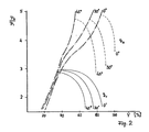
- FIG. 2 shows a characteristic field in which the ratio of the outlet-side pressure to the inlet-side pressure is plotted against the inlet-side volume flow.
- the diagram shows that with an angular adjustment of the guide vanes 5 with increasing angle a shift of the alga of the surge line shown in dash-dotted lines to the left can be achieved, the operating point characteristics being plotted for two peripheral speeds.
- the solid curve family is assigned to the lower peripheral speed and the dashed family of curves to the higher peripheral speed.
- the values of the volume flow plotted on the abscissa are relativized and plotted in percent, 100% being assigned to the volume flow occurring at the stuffing limit.
Landscapes
- Engineering & Computer Science (AREA)
- Mechanical Engineering (AREA)
- General Engineering & Computer Science (AREA)
- Supercharger (AREA)
- Output Control And Ontrol Of Special Type Engine (AREA)
- Control Of Turbines (AREA)
Priority Applications (1)
| Application Number | Priority Date | Filing Date | Title |
|---|---|---|---|
| AT87102412T ATE63980T1 (de) | 1986-04-24 | 1987-02-20 | Axialdrallregler fuer einen abgasturbolader fuer verbrennungsmotoren. |
Applications Claiming Priority (2)
| Application Number | Priority Date | Filing Date | Title |
|---|---|---|---|
| DE3613857 | 1986-04-24 | ||
| DE19863613857 DE3613857A1 (de) | 1986-04-24 | 1986-04-24 | Axialdrallregler fuer einen abgasturbolader fuer verbrennungsmotoren |
Publications (3)
| Publication Number | Publication Date |
|---|---|
| EP0243596A2 EP0243596A2 (de) | 1987-11-04 |
| EP0243596A3 EP0243596A3 (en) | 1988-07-20 |
| EP0243596B1 true EP0243596B1 (de) | 1991-05-29 |
Family
ID=6299424
Family Applications (1)
| Application Number | Title | Priority Date | Filing Date |
|---|---|---|---|
| EP87102412A Expired - Lifetime EP0243596B1 (de) | 1986-04-24 | 1987-02-20 | Axialdrallregler für einen Abgasturbolader für Verbrennungsmotoren |
Country Status (5)
| Country | Link |
|---|---|
| US (1) | US4780055A (enExample) |
| EP (1) | EP0243596B1 (enExample) |
| AT (1) | ATE63980T1 (enExample) |
| DE (2) | DE3613857A1 (enExample) |
| ES (1) | ES2022821B3 (enExample) |
Families Citing this family (25)
| Publication number | Priority date | Publication date | Assignee | Title |
|---|---|---|---|---|
| US5025629A (en) * | 1989-03-20 | 1991-06-25 | Woollenweber William E | High pressure ratio turbocharger |
| DE4002548C3 (de) * | 1990-01-29 | 1995-01-26 | Kuehnle Kopp Kausch Ag | Axialdrallregler für großvolumige Radialverdichter |
| DE4117025A1 (de) * | 1991-05-24 | 1992-11-26 | Halberg Maschbau Gmbh & Co | Drallregler fuer kreiselpumpen |
| US6012897A (en) * | 1997-06-23 | 2000-01-11 | Carrier Corporation | Free rotor stabilization |
| FR2849905B1 (fr) * | 2003-01-15 | 2007-01-05 | Renault Sa | Dispositif d'alimentation en air du compresseur d'un moteur thermique suralimente |
| EP1574684A1 (de) | 2004-03-12 | 2005-09-14 | ABB Turbo Systems AG | Regelungssystem und Verfahren zum Betreiben eines Abgasturboladers |
| DE102004039299A1 (de) * | 2004-08-13 | 2006-02-23 | Fev Motorentechnik Gmbh | Turboverdichter für eine Brennkraftmaschine |
| EP1632678A1 (de) | 2004-09-01 | 2006-03-08 | Ford Global Technologies, LLC, A subsidary of Ford Motor Company | Drallgenerator in Bögen |
| DE102005017975A1 (de) * | 2005-04-19 | 2006-11-02 | Audi Ag | Radialverdichteranordnung und Abgasturbolader mit einer Radialverdichteranordnung |
| DE102005019896B4 (de) * | 2005-04-29 | 2013-07-11 | Bayerische Motoren Werke Aktiengesellschaft | Drallerzeugungseinrichtung |
| EP1719887A1 (de) * | 2005-05-04 | 2006-11-08 | ABB Turbo Systems AG | Auflade-Regelung für Verbrennungsmotor |
| DE102005045194B4 (de) * | 2005-09-21 | 2016-06-09 | Fev Gmbh | Leiteinrichtung für einen Turboverdichter einer Brennkraftmaschine |
| GB0716060D0 (en) * | 2007-08-17 | 2007-09-26 | Cummins Turbo Technologies | An engine generator set |
| DE102008046220A1 (de) * | 2008-09-08 | 2010-03-11 | Bosch Mahle Turbo Systems Gmbh & Co. Kg | Drallerzeugungseinrichtung |
| GB0821089D0 (en) * | 2008-11-19 | 2008-12-24 | Ford Global Tech Llc | A method for improving the performance of a radial compressor |
| US20110088379A1 (en) * | 2009-10-15 | 2011-04-21 | General Electric Company | Exhaust gas diffuser |
| US9249687B2 (en) | 2010-10-27 | 2016-02-02 | General Electric Company | Turbine exhaust diffusion system and method |
| CN104040109B (zh) * | 2011-11-18 | 2017-01-18 | 哈利伯顿能源服务公司 | 具有流体二极管的自主流体控制系统 |
| DE102013018368B4 (de) | 2013-11-02 | 2016-06-02 | Iav Gmbh Ingenieurgesellschaft Auto Und Verkehr | Verstellbare Drallerzeugungseinrichtung für Verdichter |
| DE102014212606B4 (de) * | 2014-06-30 | 2020-12-17 | Ford Global Technologies, Llc | Kraftfahrzeug und Luftfilterbox |
| JP6001707B2 (ja) * | 2015-02-25 | 2016-10-05 | 株式会社オティックス | 過給機用のコンプレッサハウジング |
| US20170152860A1 (en) * | 2015-11-30 | 2017-06-01 | Borgwarner Inc. | Compressor inlet guide vanes |
| DE102017222209A1 (de) * | 2017-12-07 | 2019-06-13 | MTU Aero Engines AG | Leitschaufelanbindung sowie Strömungsmaschine |
| DE102018211091B4 (de) * | 2018-07-05 | 2025-12-24 | Volkswagen Aktiengesellschaft | Verfahren zum Betreiben einer Brennkraftmaschine und Brennkraftmaschine |
| CN116971847A (zh) * | 2023-07-28 | 2023-10-31 | 中国航发动力股份有限公司 | 一种发动机高低压可调导流叶片作动筒的更换装置及更换方法 |
Family Cites Families (15)
| Publication number | Priority date | Publication date | Assignee | Title |
|---|---|---|---|---|
| US1978128A (en) | 1932-03-14 | 1934-10-23 | Clarage Fan Company | Vortex control |
| US2412365A (en) * | 1943-10-26 | 1946-12-10 | Wright Aeronautical Corp | Variable turbine nozzle |
| US2606713A (en) * | 1948-04-26 | 1952-08-12 | Snecma | Adjustable inlet device for compressors |
| GB755527A (en) * | 1953-10-15 | 1956-08-22 | Power Jets Res & Dev Ltd | Mounting of swivelling guide vane elements in axial flow elastic fluid turbines |
| US2817475A (en) * | 1954-01-22 | 1957-12-24 | Trane Co | Centrifugal compressor and method of controlling the same |
| US2827224A (en) * | 1955-06-30 | 1958-03-18 | Buffalo Forge Co | Inlet vane actuating device |
| CH371857A (de) * | 1959-10-20 | 1963-09-15 | Bbc Brown Boveri & Cie | Schaufelverstelleinrichtung an Turbomaschine |
| US3089679A (en) * | 1960-06-06 | 1963-05-14 | Chrysler Corp | Gas turbine nozzle suspension and adjustment |
| US3096785A (en) * | 1960-06-27 | 1963-07-09 | Ingersoll Rand Co | Pipe line pump |
| US3195805A (en) * | 1961-10-25 | 1965-07-20 | Garrett Corp | Turbocharger differential pressure control |
| US3251539A (en) * | 1963-05-15 | 1966-05-17 | Westinghouse Electric Corp | Centrifugal gas compressors |
| US3362625A (en) * | 1966-09-06 | 1968-01-09 | Carrier Corp | Centrifugal gas compressor |
| JPS58167824A (ja) * | 1982-03-29 | 1983-10-04 | Hino Motors Ltd | 車両用機関のタ−ボ過給装置 |
| JPS58167825A (ja) * | 1982-03-29 | 1983-10-04 | Hino Motors Ltd | 車両用機関のタ−ボ過給装置 |
| JPS58185934A (ja) * | 1982-04-24 | 1983-10-29 | Hino Motors Ltd | 車両用機関のタ−ボ過給装置 |
-
1986
- 1986-04-24 DE DE19863613857 patent/DE3613857A1/de active Granted
-
1987
- 1987-02-20 EP EP87102412A patent/EP0243596B1/de not_active Expired - Lifetime
- 1987-02-20 ES ES87102412T patent/ES2022821B3/es not_active Expired - Lifetime
- 1987-02-20 DE DE8787102412T patent/DE3770327D1/de not_active Expired - Lifetime
- 1987-02-20 AT AT87102412T patent/ATE63980T1/de active
- 1987-04-23 US US07/041,844 patent/US4780055A/en not_active Expired - Fee Related
Also Published As
| Publication number | Publication date |
|---|---|
| EP0243596A2 (de) | 1987-11-04 |
| ATE63980T1 (de) | 1991-06-15 |
| ES2022821B3 (es) | 1991-12-16 |
| DE3613857A1 (de) | 1987-10-29 |
| DE3613857C2 (enExample) | 1988-07-28 |
| EP0243596A3 (en) | 1988-07-20 |
| DE3770327D1 (de) | 1991-07-04 |
| US4780055A (en) | 1988-10-25 |
Similar Documents
| Publication | Publication Date | Title |
|---|---|---|
| EP0243596B1 (de) | Axialdrallregler für einen Abgasturbolader für Verbrennungsmotoren | |
| EP1488084B1 (de) | Variabler abgasturbolader | |
| EP0093462B1 (de) | Abgasturbolader mit verstellbarem Ringschieber | |
| DE4242494C1 (en) | Adjustable flow-guide for engine exhaust turbocharger - has axially-adjustable annular insert in sectors forming different kinds of guide grilles supplied simultaneously by spiral passages | |
| DE102018221812B4 (de) | Abgasturbine mit einer Abgasleiteinrichtung für einen Abgasturbolader und Abgasturbolader | |
| DE112009004260T5 (de) | Vereinfachter Turbolader mit veränderlicher Geometrie und Schaufelringen | |
| DE3833906C2 (enExample) | ||
| EP3682115B1 (de) | Verdichter für eine aufladevorrichtung einer brennkraftmaschine und aufladevorrichtung für eine brennkraftmaschine | |
| WO2008125384A1 (de) | Abgasturbolader | |
| EP3542069B1 (de) | Verdichter, abgasturbolader und brennkraftmaschine | |
| EP0991856B1 (de) | Brennkraftmaschinen - turbolader - system | |
| DE102021122921A1 (de) | Einlasssystem, beinhaltend einen turbolader mit geteiltem spiralgehäuse, der eine variable turbinengeometrie mit aerodynamischen abstandshaltern und einen leitschaufelkranz mit einer mehrzahl von drehbaren leitschaufeln aufweist | |
| EP3682116A1 (de) | Radialverdichter mit einem irisblendenmechanismus für eine aufladevorrichtung eines verbrennungsmotors, aufladevorrichtung und lamelle für den irisblendenmechanismus | |
| EP0086466B1 (de) | Durchflussregelung für den Spiralgehäuse-einlass einer Radialturbine | |
| DE3105179A1 (de) | "einen verdichter antreibender abgas-turbolader fuer eine mit veraenderlicher last und drehzahl betriebene brennkraftmaschine" | |
| EP3056690B1 (de) | Radialverdichter, abgasturbolader und entsprechendes verfahren zum betreiben eines radialverdichters | |
| DE3528225A1 (de) | Turbolader | |
| DE102013007333A1 (de) | Verdichter einer Ladeeinrichtung einer Brennkraftmaschine und Verfahren zum Betreiben eines Verdichters einer Ladeeinrichtung einer Brennkraftmaschine | |
| DE102014215885B3 (de) | Aufgeladene Brennkraftmaschine mit Mixed-Flow-Turbine | |
| DE102012012000B4 (de) | Turbine für einen Abgasturbolader | |
| DE102018212756B3 (de) | Radialverdichter, Aufladevorrichtung und Brennkraftmaschine mit Abgasrückführeinrichtung | |
| EP1201881B1 (de) | Abgasturbolader | |
| DE102014220680A1 (de) | Brennkraftmaschine mit Mixed-Flow-Turbine umfassend eine Leiteinrichtung | |
| DE2948089A1 (de) | Turbolader fuer brennkraftmaschinen, insbesondere mehrflutiger abgasturbolader fuer motoren von kraftfahrzeugen | |
| DE10217470A1 (de) | Abgasturbine |
Legal Events
| Date | Code | Title | Description |
|---|---|---|---|
| PUAI | Public reference made under article 153(3) epc to a published international application that has entered the european phase |
Free format text: ORIGINAL CODE: 0009012 |
|
| 17P | Request for examination filed |
Effective date: 19870318 |
|
| AK | Designated contracting states |
Kind code of ref document: A2 Designated state(s): AT CH DE ES FR GB IT LI |
|
| PUAL | Search report despatched |
Free format text: ORIGINAL CODE: 0009013 |
|
| AK | Designated contracting states |
Kind code of ref document: A3 Designated state(s): AT CH DE ES FR GB IT LI |
|
| 17Q | First examination report despatched |
Effective date: 19890913 |
|
| GRAA | (expected) grant |
Free format text: ORIGINAL CODE: 0009210 |
|
| AK | Designated contracting states |
Kind code of ref document: B1 Designated state(s): AT CH DE ES FR GB IT LI |
|
| REF | Corresponds to: |
Ref document number: 63980 Country of ref document: AT Date of ref document: 19910615 Kind code of ref document: T |
|
| ET | Fr: translation filed | ||
| GBT | Gb: translation of ep patent filed (gb section 77(6)(a)/1977) | ||
| REF | Corresponds to: |
Ref document number: 3770327 Country of ref document: DE Date of ref document: 19910704 |
|
| ITF | It: translation for a ep patent filed | ||
| PLBE | No opposition filed within time limit |
Free format text: ORIGINAL CODE: 0009261 |
|
| STAA | Information on the status of an ep patent application or granted ep patent |
Free format text: STATUS: NO OPPOSITION FILED WITHIN TIME LIMIT |
|
| 26N | No opposition filed | ||
| PGFP | Annual fee paid to national office [announced via postgrant information from national office to epo] |
Ref country code: GB Payment date: 19940131 Year of fee payment: 8 |
|
| PGFP | Annual fee paid to national office [announced via postgrant information from national office to epo] |
Ref country code: FR Payment date: 19940204 Year of fee payment: 8 |
|
| PGFP | Annual fee paid to national office [announced via postgrant information from national office to epo] |
Ref country code: AT Payment date: 19940211 Year of fee payment: 8 |
|
| PGFP | Annual fee paid to national office [announced via postgrant information from national office to epo] |
Ref country code: ES Payment date: 19940221 Year of fee payment: 8 |
|
| PGFP | Annual fee paid to national office [announced via postgrant information from national office to epo] |
Ref country code: CH Payment date: 19940311 Year of fee payment: 8 |
|
| PG25 | Lapsed in a contracting state [announced via postgrant information from national office to epo] |
Ref country code: GB Effective date: 19950220 Ref country code: AT Effective date: 19950220 |
|
| PG25 | Lapsed in a contracting state [announced via postgrant information from national office to epo] |
Ref country code: ES Free format text: LAPSE BECAUSE OF NON-PAYMENT OF DUE FEES Effective date: 19950221 |
|
| PG25 | Lapsed in a contracting state [announced via postgrant information from national office to epo] |
Ref country code: LI Effective date: 19950228 Ref country code: CH Effective date: 19950228 |
|
| GBPC | Gb: european patent ceased through non-payment of renewal fee |
Effective date: 19950220 |
|
| PG25 | Lapsed in a contracting state [announced via postgrant information from national office to epo] |
Ref country code: FR Effective date: 19951031 |
|
| REG | Reference to a national code |
Ref country code: FR Ref legal event code: ST |
|
| REG | Reference to a national code |
Ref country code: ES Ref legal event code: FD2A Effective date: 19990301 |
|
| PGFP | Annual fee paid to national office [announced via postgrant information from national office to epo] |
Ref country code: DE Payment date: 20040227 Year of fee payment: 18 |
|
| PG25 | Lapsed in a contracting state [announced via postgrant information from national office to epo] |
Ref country code: IT Free format text: LAPSE BECAUSE OF NON-PAYMENT OF DUE FEES Effective date: 20050220 |
|
| PG25 | Lapsed in a contracting state [announced via postgrant information from national office to epo] |
Ref country code: DE Free format text: LAPSE BECAUSE OF NON-PAYMENT OF DUE FEES Effective date: 20050901 |