EP0242584A1 - Dispositif pour le découplage mécanique d'une tuyauterie - Google Patents
Dispositif pour le découplage mécanique d'une tuyauterie Download PDFInfo
- Publication number
- EP0242584A1 EP0242584A1 EP87103788A EP87103788A EP0242584A1 EP 0242584 A1 EP0242584 A1 EP 0242584A1 EP 87103788 A EP87103788 A EP 87103788A EP 87103788 A EP87103788 A EP 87103788A EP 0242584 A1 EP0242584 A1 EP 0242584A1
- Authority
- EP
- European Patent Office
- Prior art keywords
- pipe
- fixed point
- clamps
- distances
- brackets
- Prior art date
- Legal status (The legal status is an assumption and is not a legal conclusion. Google has not performed a legal analysis and makes no representation as to the accuracy of the status listed.)
- Granted
Links
- 239000000463 material Substances 0.000 description 3
- 238000012360 testing method Methods 0.000 description 3
- 239000011150 reinforced concrete Substances 0.000 description 2
- 229910000831 Steel Inorganic materials 0.000 description 1
- 238000010276 construction Methods 0.000 description 1
- 238000004519 manufacturing process Methods 0.000 description 1
- 239000010959 steel Substances 0.000 description 1
Images


Classifications
-
- F—MECHANICAL ENGINEERING; LIGHTING; HEATING; WEAPONS; BLASTING
- F16—ENGINEERING ELEMENTS AND UNITS; GENERAL MEASURES FOR PRODUCING AND MAINTAINING EFFECTIVE FUNCTIONING OF MACHINES OR INSTALLATIONS; THERMAL INSULATION IN GENERAL
- F16L—PIPES; JOINTS OR FITTINGS FOR PIPES; SUPPORTS FOR PIPES, CABLES OR PROTECTIVE TUBING; MEANS FOR THERMAL INSULATION IN GENERAL
- F16L3/00—Supports for pipes, cables or protective tubing, e.g. hangers, holders, clamps, cleats, clips, brackets
Definitions
- the invention relates to a device for the mechanical decoupling of a pipeline system, which has at least one connecting pipe piece, with which straight pipe sections of different directions are connected starting from a connection point, pipelines of the pipeline system being connected to a building at the same distances depending on the load capacity of the pipes Brackets are stored and, so that vibrations of the piping system can be calculated, are held immovably by at least one fixed point bracket.
- a known device for the mechanical decoupling of a pipeline system consists of a complex, heavy fixed point fitting made of steel, which is anchored in the reinforced concrete structure of a building is and comprises a pipe of the piping system over a certain length. Such a fixed point fitting ensures that the pipeline at the fixed point is not deflected even by the greatest possible external forces.
- the invention has for its object to develop a device for the mechanical decoupling of a pipeline system, which manages with simple and light brackets for the pipelines and nevertheless ensures a fixed point necessary for the calculation of the pipeline system.
- the work and material costs should be significantly reduced compared to the use of fixed point fittings.
- brackets are, without exception, commercially available pipe clamps, that three pipe clamps are arranged in the region of a connecting pipe piece as a fixed point holder of the pipe system, at least on each of the differently directed pipe sections a pipe clamp is arranged so that the three pipe clamps form the corners of a triangle, and that the distances between the connection point of the differently directed pipe sections and the adjacent pipe clamps forming the fixed point holder and between two immediately adjacent pipe clamps forming the fixed point holder are considerably shorter than the distances between the other supports for the piping system used exclusively for storage.
- Such a device for the mechanical decoupling of a pipeline system acts like a high-pass filter between the parts of the system.
- each individual commercially available pipe clamp is not able to prevent possible vibrations of the pipe, the combination of three such pipe clamps, which are arranged at short intervals in the manner of a triangle, ensures a fixed point of the piping system that is necessary for the calculation.
- a connecting pipe piece in a pipe system is, for example, a pipe bend which is connected to two straight pipe sections.
- the connection point is the vertex of the pipe bend, which by definition is the point at which the imaginary extensions of the straight pipe sections intersect.
- a fixed point becomes in the area of the pipe bend formed by two pipe clamps arranged in front of the pipe bend and one behind the pipe bend on the straight pipe sections.
- An equivalent fixed point is formed if one pipe clamp is positioned in front of and two behind the pipe bend.
- the distances between the apex of the pipe bend and the two pipe clamps adjacent to the pipe bend of the fixed point are considerably shorter than the distances between the brackets used exclusively for storage.
- the two pipe clamps of the fixed point immediately adjacent to the straight pipe section have the same short distance.
- a device according to the invention for mechanical decoupling of the piping system can be attached anywhere.
- a suitable connecting pipe piece for arranging a fixed point is a T-piece, with which three straight pipe sections are connected.
- the junction point of the T-piece is to be regarded as the connection point.
- the fixed point is formed by a pipe clamp in each pipe section adjacent to the T-piece. The distances between the branch point of the T-piece and the three neighboring pipe clamps are considerably shorter than the distances between the other supports of the pipe system that are used exclusively for storage.
- Every pipe system contains pipe bends and usually also T-pieces.
- the device according to the invention for mechanical decoupling of the piping system can consequently be used on any piping system.
- the distances between the connection point of the differently directed pipe sections and the adjacent pipe clips as well as the distance between two fixed point pipe clips directly adjacent to a pipe section are significantly shorter than the distances the other brackets.
- a stable fixed point for the calculation of the pipeline system is ensured if the distances within the device according to the invention are between 9 and 11 hundredths of a distance between the other supports of the pipeline system which are used exclusively for storage and are arranged at equal intervals.
- the regular distances between the brackets of the pipe system are specified and depend on the material, the wall thickness and the diameter of the pipes.
- the distances within the decoupling device according to the invention are in the relationship according to the invention to the regular intervals. This has the advantage that a stable fixed point on the pipe system to build simple commercially available pipe clamps that are easy to handle and assemble.
- the distances provided according to the invention within the decoupling device according to the invention are so large that the weld seams on the pipe bend and on the T-piece are accessible at any time even for weld seam testing devices.
- the advantage of the invention is that a fixed point on the system which is necessary for the calculation of the piping system can be easily set up with simple means.
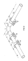
- Pipes 1 of a pipe system are firmly connected to a building by brackets 2.
- the bracket distance L R is determined by the mechanical properties of the pipes.
- the same is on pipes of the same type Bracket distance L R constant.
- the device according to the invention for mechanical decoupling consists of three commercially available pipe clamps 21 to 23 or 24 to 26, which are arranged on a small space compared to the mounting distance L R so that they form the corners of a triangle.
- the device according to the invention is arranged according to FIG. 1 in the area of a pipe bend 11.
- pipe clips 21 and 22 adjacent to the pipe bend 11 are located at a distance L E from the apex 110 of the pipe bend 11 on the pipe 1.
- the third pipe clip 23 is arranged on one of the straight legs of the pipe 1 at a distance L E from the adjacent pipe clip 22 .
- the distance L E within the device according to the invention for mechanical decoupling is one tenth of a mounting distance L R required on the rest of the piping system.
- a commercially available pipe clamp 24 to 26 is arranged at a distance L E from the branch point 120 on each pipeline branch.
- the three pipe clamps 24 to 26 form the corners of a triangle.
- Their distances L E from branch point 120 are one tenth of the bracket distance L R on the piping system.
- a device according to the invention for mechanical decoupling of a pipeline system which is arranged in the region of a pipe bend 11 according to FIG. 1, is shown in perspective in FIG. 3.
- the pipe bend 11 is welded to straight pipe sections 13 and 14 with weld seams 31.
- the commercially available pipe clamps 21 and 22 are attached to the straight pipe sections 13 and 14 on both sides of the pipe bend 11.
- the distance L E according to the invention from the vertex 110 of the pipe bend 11 is sufficiently large so that the weld seams 31 can be examined at any time even with test equipment.
- the third pipe clamp 23, which forms the device according to the invention together with the two other pipe clamps 21 and 22, is arranged on the straight pipe section 14 at a distance L E from the pipe clamp 22.
- the pipe clamp 23 can also be arranged on the straight pipe section 13 at a distance L E from the pipe clamp 21.
- a device according to the invention for the mechanical decoupling of a pipeline system in the region of a pipeline branch is shown in perspective in FIG. 4.
- the branch is realized by a T-piece 12 to which straight pipe sections 15, 16 and 17 are welded.
- the three pipe clamps 24 to 26 arranged on the straight pipe pieces 15, 16 and 17 are arranged from the branch point 120 in the T-piece 12 at the distance L E according to the invention.
- This distance L E according to the invention is so large that the welds 32 between the T-piece 12 and the straight pipe sections 15, 16 and 17 can be checked at any time even with test equipment.
- the pipe clamps 21 to 23, 24 to 26 are arranged according to the invention on the piping system so that they form the corners of a triangle.
- a decoupling device according to the invention is therefore arranged in the region of a pipe bend 11 or a T-piece 12.
- the arrangement of the pipe clamps 21 to 23, 24 to 26 in the form of a triangle and the spatial distances within this arrangement work together in such a way that a mechanical decoupling of the piping system is achieved which is equivalent to that of a rigid fixed point.
Landscapes
- Engineering & Computer Science (AREA)
- General Engineering & Computer Science (AREA)
- Mechanical Engineering (AREA)
- Supports For Pipes And Cables (AREA)
- Pipeline Systems (AREA)
Applications Claiming Priority (2)
| Application Number | Priority Date | Filing Date | Title |
|---|---|---|---|
| DE3610331 | 1986-03-26 | ||
| DE3610331 | 1986-03-26 |
Publications (2)
| Publication Number | Publication Date |
|---|---|
| EP0242584A1 true EP0242584A1 (fr) | 1987-10-28 |
| EP0242584B1 EP0242584B1 (fr) | 1990-12-05 |
Family
ID=6297376
Family Applications (1)
| Application Number | Title | Priority Date | Filing Date |
|---|---|---|---|
| EP87103788A Expired - Lifetime EP0242584B1 (fr) | 1986-03-26 | 1987-03-16 | Dispositif pour le découplage mécanique d'une tuyauterie |
Country Status (6)
| Country | Link |
|---|---|
| US (1) | US4783030A (fr) |
| EP (1) | EP0242584B1 (fr) |
| JP (1) | JPS62233586A (fr) |
| CA (1) | CA1321185C (fr) |
| DE (1) | DE3766531D1 (fr) |
| ES (1) | ES2018490B3 (fr) |
Cited By (2)
| Publication number | Priority date | Publication date | Assignee | Title |
|---|---|---|---|---|
| GB2221009A (en) * | 1988-05-20 | 1990-01-24 | Lisega Gmbh | Pipe support |
| EP0427880A1 (fr) * | 1989-11-13 | 1991-05-22 | Siemens Aktiengesellschaft | Support pour tuyaux et méthode de son fabrication |
Families Citing this family (20)
| Publication number | Priority date | Publication date | Assignee | Title |
|---|---|---|---|---|
| US4927201A (en) * | 1988-12-27 | 1990-05-22 | Andrew Froutzis | Means for releasably anchoring vehicle seats |
| US5393024A (en) * | 1990-09-12 | 1995-02-28 | Daubenspeck; Richard P. | Water heater tank support |
| US5741458A (en) * | 1996-01-19 | 1998-04-21 | Rowley; William | Method of forming a water heater tube |
| US6254051B1 (en) | 1997-01-15 | 2001-07-03 | Securus, Inc. | Restraining system for water heaters |
| US5897086A (en) * | 1997-08-15 | 1999-04-27 | Quick Strap, Inc. | System and method for restraining water heaters from tipping over due to earthquake or severe winds |
| US6095472A (en) * | 1998-01-14 | 2000-08-01 | Securus, Inc. | Restraining system for water heaters |
| US6254052B1 (en) | 1998-01-14 | 2001-07-03 | Securus, Inc. | Restraining system for water heaters |
| US6190261B1 (en) * | 1998-09-15 | 2001-02-20 | Flowserve Management Company | Pump assembly shaft guard |
| US6481803B2 (en) * | 2001-01-16 | 2002-11-19 | Kennametal Inc. | Universal bit holder block connection surface |
| US6527233B2 (en) * | 2001-04-24 | 2003-03-04 | Inertia Dynamics, Inc. | Device for clamping a shaft |
| US20030038217A1 (en) * | 2001-08-22 | 2003-02-27 | Rivers James Michael | Adjustable support strap for pipes and the like |
| US6729588B2 (en) * | 2001-11-16 | 2004-05-04 | Wilkinson, Iii Joseph | Pipe shoe and method |
| US7093727B2 (en) | 2004-09-14 | 2006-08-22 | Musico M James | Plural utensils support system |
| US20060175338A1 (en) * | 2004-12-16 | 2006-08-10 | Pishock Charles T Jr | Tank outlet fitting with flange |
| US7153064B2 (en) * | 2005-02-25 | 2006-12-26 | Playstar, Inc. | Pipe sleeve for a floating dock |
| US7331549B2 (en) * | 2005-06-03 | 2008-02-19 | Woodworker's Supply Inc. | Pipe brackets and pipe hanging system |
| EP2423516B1 (fr) * | 2009-04-23 | 2016-03-16 | KYB Corporation | Structure de fixation de tube pour tuyau cylindrique |
| JP5445507B2 (ja) * | 2010-06-03 | 2014-03-19 | 株式会社デンソー | 電力変換装置 |
| EP3124843B1 (fr) * | 2014-03-28 | 2020-01-22 | Public Joint Stock Company "Transneft" | Procédé d'installation de support immobile en position voulue |
| NL2019747B1 (en) * | 2017-10-17 | 2019-04-24 | Walraven Holding Bv J Van | Riser clamp with a vibration isolation element |
Citations (3)
| Publication number | Priority date | Publication date | Assignee | Title |
|---|---|---|---|---|
| CH385116A (de) * | 1959-10-24 | 1964-11-30 | Voest Ag | Druckrohrleitung für Wasserkraftanlagen |
| US3539137A (en) * | 1968-03-25 | 1970-11-10 | Birma Products Corp | Pipe saddle |
| GB2088515A (en) * | 1980-11-28 | 1982-06-09 | Italiana Serrature Torino | Flexible pipe |
Family Cites Families (2)
| Publication number | Priority date | Publication date | Assignee | Title |
|---|---|---|---|---|
| US3936001A (en) * | 1974-12-09 | 1976-02-03 | Bolton-Emerson, Inc. | Anti-sag device for paper mill showers |
| US4513934A (en) * | 1982-11-03 | 1985-04-30 | Miro Industries, Inc. | Pipe-supporting device |
-
1987
- 1987-03-16 ES ES87103788T patent/ES2018490B3/es not_active Expired - Lifetime
- 1987-03-16 EP EP87103788A patent/EP0242584B1/fr not_active Expired - Lifetime
- 1987-03-16 DE DE8787103788T patent/DE3766531D1/de not_active Expired - Lifetime
- 1987-03-20 JP JP62067701A patent/JPS62233586A/ja active Pending
- 1987-03-24 CA CA000532862A patent/CA1321185C/fr not_active Expired - Fee Related
- 1987-03-25 US US07/030,740 patent/US4783030A/en not_active Expired - Fee Related
Patent Citations (3)
| Publication number | Priority date | Publication date | Assignee | Title |
|---|---|---|---|---|
| CH385116A (de) * | 1959-10-24 | 1964-11-30 | Voest Ag | Druckrohrleitung für Wasserkraftanlagen |
| US3539137A (en) * | 1968-03-25 | 1970-11-10 | Birma Products Corp | Pipe saddle |
| GB2088515A (en) * | 1980-11-28 | 1982-06-09 | Italiana Serrature Torino | Flexible pipe |
Non-Patent Citations (2)
| Title |
|---|
| CHEMICAL ENGINEERING; Band 73, 14. Februar 1966, Seiten 153-160, New York, US; J. KIVEN "Controlling thermal expansion in piping systems" * |
| HEATING/PIPING/AIR CONDITIONING, Band 57, Nr. 12, Dezember 1985, Seiten 135-138, Stamford, Connecticut, US; J. HABJAN "Duct hanger location guidelines" * |
Cited By (3)
| Publication number | Priority date | Publication date | Assignee | Title |
|---|---|---|---|---|
| GB2221009A (en) * | 1988-05-20 | 1990-01-24 | Lisega Gmbh | Pipe support |
| GB2221009B (en) * | 1988-05-20 | 1992-09-09 | Lisega Gmbh | Pipe support |
| EP0427880A1 (fr) * | 1989-11-13 | 1991-05-22 | Siemens Aktiengesellschaft | Support pour tuyaux et méthode de son fabrication |
Also Published As
| Publication number | Publication date |
|---|---|
| JPS62233586A (ja) | 1987-10-13 |
| CA1321185C (fr) | 1993-08-10 |
| US4783030A (en) | 1988-11-08 |
| DE3766531D1 (de) | 1991-01-17 |
| ES2018490B3 (es) | 1991-04-16 |
| EP0242584B1 (fr) | 1990-12-05 |
Similar Documents
| Publication | Publication Date | Title |
|---|---|---|
| EP0242584B1 (fr) | Dispositif pour le découplage mécanique d'une tuyauterie | |
| EP1388619B1 (fr) | Dispositif pour fixer un tuyau | |
| DE19804358A1 (de) | Führungseinrichtung für Rohre | |
| EP3406501B1 (fr) | Véhicule pourvu d'au moins un dispositif de canal et procédé permettant d'équiper un véhicule d'un dispositif de canal | |
| DE4224483C2 (de) | Montageschiene | |
| DE3406955C2 (fr) | ||
| DE202015104363U1 (de) | Konsole zum Abstützen einer Rohrschelle | |
| DE2427444C2 (de) | Bauwerksknoten | |
| DE2223076B2 (de) | Gebäudeskelett mit Installationsleitungen | |
| WO2014140714A1 (fr) | Pièce de raccordement de tuyau | |
| DE112019006843T5 (de) | Warmwasser-Versorgungseinrichtung | |
| EP0046519B1 (fr) | Grillage porteur pour éléments de chauffage d'un sol chauffant | |
| DE9405929U1 (de) | Vorrichtung zur axialen Abstützung einer an einer Tragkonstruktion angebrachten Rohrleitung | |
| DE3041908A1 (de) | Freitragendes lagerregal | |
| DE102021128569B3 (de) | Instrumententafelträger für ein Kraftfahrzeug | |
| DE2416074A1 (de) | Anordnung von heizkoerpern und den zugeordneten vor- und ruecklaufleitungen bei zentralheizungssystemen | |
| DE29808529U1 (de) | Installationsmodul | |
| DE7922652U1 (de) | Befestigungselement für Rohre, Schläuche, Kabel o.a. Gegenstände mit zylindrischer Oberfläche | |
| DE8807095U1 (de) | Bausatz zum Aufbau eines Doppelrohr-Leitungssystems | |
| EP0949440A1 (fr) | Elément flexible de raccordement pour installations de tuyaux | |
| EP0679830A2 (fr) | Elément de branchement pour tuyaux | |
| DE8413621U1 (de) | Vorrichtung zur Aufnahme und Montage von Rohrleitungen | |
| DE1037544B (de) | Aufhaengung von Hohlleitern an Tragdraehten, die von Mast zu Mast gespannt sind, insbesondere von Hohlleitern fuer die UEbertragung elektromagnetischer Wellen vom H-Modus | |
| AT274102B (de) | Knieförmige Kupplung zur Verbindung von Installationsrohren | |
| DE8527900U1 (de) | Haltevorrichtung für elektrische Bauteile in einem Zähler- oder Verteilerschrank |
Legal Events
| Date | Code | Title | Description |
|---|---|---|---|
| PUAI | Public reference made under article 153(3) epc to a published international application that has entered the european phase |
Free format text: ORIGINAL CODE: 0009012 |
|
| AK | Designated contracting states |
Kind code of ref document: A1 Designated state(s): BE CH DE ES FR GB LI |
|
| 17P | Request for examination filed |
Effective date: 19880125 |
|
| 17Q | First examination report despatched |
Effective date: 19890224 |
|
| GRAA | (expected) grant |
Free format text: ORIGINAL CODE: 0009210 |
|
| AK | Designated contracting states |
Kind code of ref document: B1 Designated state(s): BE CH DE ES FR GB LI |
|
| REF | Corresponds to: |
Ref document number: 3766531 Country of ref document: DE Date of ref document: 19910117 |
|
| GBT | Gb: translation of ep patent filed (gb section 77(6)(a)/1977) | ||
| ET | Fr: translation filed | ||
| PLBE | No opposition filed within time limit |
Free format text: ORIGINAL CODE: 0009261 |
|
| STAA | Information on the status of an ep patent application or granted ep patent |
Free format text: STATUS: NO OPPOSITION FILED WITHIN TIME LIMIT |
|
| 26N | No opposition filed | ||
| PGFP | Annual fee paid to national office [announced via postgrant information from national office to epo] |
Ref country code: GB Payment date: 19940218 Year of fee payment: 8 |
|
| PGFP | Annual fee paid to national office [announced via postgrant information from national office to epo] |
Ref country code: BE Payment date: 19940308 Year of fee payment: 8 |
|
| PG25 | Lapsed in a contracting state [announced via postgrant information from national office to epo] |
Ref country code: GB Effective date: 19950316 |
|
| PGFP | Annual fee paid to national office [announced via postgrant information from national office to epo] |
Ref country code: FR Payment date: 19950323 Year of fee payment: 9 |
|
| PG25 | Lapsed in a contracting state [announced via postgrant information from national office to epo] |
Ref country code: BE Effective date: 19950331 |
|
| PGFP | Annual fee paid to national office [announced via postgrant information from national office to epo] |
Ref country code: DE Payment date: 19950518 Year of fee payment: 9 |
|
| PGFP | Annual fee paid to national office [announced via postgrant information from national office to epo] |
Ref country code: CH Payment date: 19950614 Year of fee payment: 9 |
|
| BERE | Be: lapsed |
Owner name: SIEMENS A.G. Effective date: 19950331 |
|
| GBPC | Gb: european patent ceased through non-payment of renewal fee |
Effective date: 19950316 |
|
| PGFP | Annual fee paid to national office [announced via postgrant information from national office to epo] |
Ref country code: ES Payment date: 19960311 Year of fee payment: 10 |
|
| PG25 | Lapsed in a contracting state [announced via postgrant information from national office to epo] |
Ref country code: LI Effective date: 19960331 Ref country code: CH Effective date: 19960331 |
|
| REG | Reference to a national code |
Ref country code: CH Ref legal event code: PL |
|
| PG25 | Lapsed in a contracting state [announced via postgrant information from national office to epo] |
Ref country code: FR Effective date: 19961129 |
|
| PG25 | Lapsed in a contracting state [announced via postgrant information from national office to epo] |
Ref country code: DE Effective date: 19961203 |
|
| REG | Reference to a national code |
Ref country code: FR Ref legal event code: ST |
|
| PG25 | Lapsed in a contracting state [announced via postgrant information from national office to epo] |
Ref country code: ES Free format text: LAPSE BECAUSE OF NON-PAYMENT OF DUE FEES Effective date: 19970317 |
|
| REG | Reference to a national code |
Ref country code: ES Ref legal event code: FD2A Effective date: 19990201 |