EP0241973A2 - Plaquette de coupe pour l'usinage - Google Patents
Plaquette de coupe pour l'usinage Download PDFInfo
- Publication number
- EP0241973A2 EP0241973A2 EP87200573A EP87200573A EP0241973A2 EP 0241973 A2 EP0241973 A2 EP 0241973A2 EP 87200573 A EP87200573 A EP 87200573A EP 87200573 A EP87200573 A EP 87200573A EP 0241973 A2 EP0241973 A2 EP 0241973A2
- Authority
- EP
- European Patent Office
- Prior art keywords
- cutting edge
- cutting
- machining
- plane
- cutting insert
- Prior art date
- Legal status (The legal status is an assumption and is not a legal conclusion. Google has not performed a legal analysis and makes no representation as to the accuracy of the status listed.)
- Granted
Links
Images
Classifications
-
- B—PERFORMING OPERATIONS; TRANSPORTING
- B23—MACHINE TOOLS; METAL-WORKING NOT OTHERWISE PROVIDED FOR
- B23B—TURNING; BORING
- B23B27/00—Tools for turning or boring machines; Tools of a similar kind in general; Accessories therefor
- B23B27/04—Cutting-off tools
- B23B27/045—Cutting-off tools with chip-breaking arrangements
Definitions
- the invention relates to a cutting insert for machining, in particular for grooving tools with at least one cutting edge, each of which is curved or composed of one or more curved and / or straight sections, which are adjoined by a correspondingly shaped rake surface.
- Such cutting inserts are described for example in DE-OS 23 59 892 and in DE-AS 19 50 037.
- the cutting insert according to DE-OS 23 59 892 has a concave cutting edge with a correspondingly shaped rake surface. This special design achieves good chip compression, so that the chips do not jam or bake in the machining groove produced and break easily.
- the cutting insert according to DE-AS 19 50 037 has an articulated cutting edge of a very special configuration, by means of which each running chip is to be divided in its width, so that a better chip flow and a lower thermal load on the cutting insert are to be brought about.
- a disadvantage of both cutting inserts is that the special shape of the cutting edge results in a groove base of the machining groove which does not run straight, but rather is adapted to the shape of the cutting edge. For this reason, these cutting inserts are primarily only suitable for parting off. Grooving work that requires a groove with the groove base as straight as possible is not possible with these cutting inserts.
- a disadvantage of this type of cutting insert is that the chip is only deformed in the area after the cutting edge bevel, so that in turn insufficient chip deformation and thus clamping of the chips in the machining groove can occur.
- the invention has for its object to provide a cutting insert of the type mentioned, which enables optimal chip deformation and at the same time results in a machining surface that runs parallel to the cutting edge.
- the free surface of the respective shape of the cutting edge is adapted so that the vertical projection of the cutting edge on a plane results in a straight line, with a normal of the plane on the cutting edge with the free surface at least approximately that during machining included clearance angle.
- the essential advantage of the configuration according to the invention can be achieved with cutting inserts for lancing processing.
- cutting inserts for lancing processing.
- a machining groove with a straight groove base running parallel to the cutting edge is made possible without having to make any compromises with regard to optimal chip formation.
- Such cutting inserts are therefore ideally suited for grooving work.
- the design according to the invention also improves the machining workpiece surface in cutting inserts for other machining operations.
- cutting inserts for threading or milling can be provided with the configuration according to the invention.
- the cutting inserts according to the invention can be produced without difficulty using modern grinding devices.
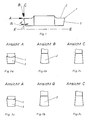
- Figures 1 and 2 show a double-sided insert for grooving.
- the cutting edge -1- is concave in view A as seen on the end face of the cutting insert. Following the cutting edge -1- there follows a correspondingly shaped rake surface -2-.
- the shape of the insert is positive, which means that the flank -3- is inclined at a clearance angle ⁇ .
- the free surface -3- is slightly convex, in such a way that the cutting edge -1- seen in view C, that is the vertical projection of the cutting edge -1- of the indexable insert in the cutting position onto the plane - E-, straight.
- the plane -E- runs parallel to the base surface -4- of the cutting insert.
- FIG. 3a A further conceivable embodiment of the cutting edge -1- of the cutting insert shown in FIG. 1 is shown in FIG. 3a in order to illustrate the principle according to the invention.
- the type of flank formation depends on the size of the clearance angle ⁇ of the cutting insert, but is always seen in view B in the mirror image of the rake face -2- shown in view A.
- the larger the clearance angle ⁇ the more pronounced the shape of the clearance -3-. Since the clearance angle is only about 6 ° -10 ° in practice, the shape of the clearance surface is very weak.
- the shapes of the open space shown in FIGS. 2b and 3b are not realistic, but rather somewhat exaggerated in order to make the type of design easier to recognize.
- the invention can of course be implemented not only with positive cutting inserts, but also with negative ones. If the geometry is negative, the cutting insert must be inclined for machining so that the required clearance angle ⁇ of the clearance -3- results. In cutting inserts with negative geometry, the free area is adapted to the rake face in such a way that when these cutting inserts are inclined by the most advantageous clearance angle ⁇ for machining, the vertical projection of the cutting edge gives the plane -E- a straight line. In this case, the plane -E- does not run parallel to the base surface -4- of the cutting insert, but is inclined to it by the clearance angle ⁇ .
Landscapes
- Engineering & Computer Science (AREA)
- Mechanical Engineering (AREA)
- Cutting Tools, Boring Holders, And Turrets (AREA)
- Turning (AREA)
- Milling Processes (AREA)
Applications Claiming Priority (2)
| Application Number | Priority Date | Filing Date | Title |
|---|---|---|---|
| AT958/86 | 1986-04-14 | ||
| AT0095886A AT387351B (de) | 1986-04-14 | 1986-04-14 | Schneideinsatz zur spanabhebenden bearbeitung |
Publications (3)
| Publication Number | Publication Date |
|---|---|
| EP0241973A2 true EP0241973A2 (fr) | 1987-10-21 |
| EP0241973A3 EP0241973A3 (en) | 1989-09-20 |
| EP0241973B1 EP0241973B1 (fr) | 1992-12-09 |
Family
ID=3503734
Family Applications (1)
| Application Number | Title | Priority Date | Filing Date |
|---|---|---|---|
| EP87200573A Expired - Lifetime EP0241973B1 (fr) | 1986-04-14 | 1987-03-26 | Plaquette de coupe pour l'usinage |
Country Status (4)
| Country | Link |
|---|---|
| EP (1) | EP0241973B1 (fr) |
| AT (1) | AT387351B (fr) |
| DE (1) | DE3782961D1 (fr) |
| ES (1) | ES2036203T3 (fr) |
Cited By (6)
| Publication number | Priority date | Publication date | Assignee | Title |
|---|---|---|---|---|
| EP0257002A3 (fr) * | 1986-08-15 | 1989-08-30 | Sandvik Aktiebolag | Outil de coupe |
| WO1991008071A1 (fr) * | 1989-11-23 | 1991-06-13 | Hertel Ag Werkzeuge + Hartstoffe | Outil a tronçonner |
| RU2199418C2 (ru) * | 1999-06-07 | 2003-02-27 | Самарский государственный технический университет | Способ отрезки резанием и инструмент для его осуществления |
| US7264425B1 (en) | 2006-02-15 | 2007-09-04 | Seco Tools Ab | Tool |
| US9592560B2 (en) | 2013-03-22 | 2017-03-14 | Kennametal India Limited | Cutting insert with a linear and a concave cutting edge portion |
| US9724761B2 (en) | 2013-03-22 | 2017-08-08 | Kennametal India Limited | Cutting insert with a linear and a concave cutting edge portion |
Family Cites Families (8)
| Publication number | Priority date | Publication date | Assignee | Title |
|---|---|---|---|---|
| US2688791A (en) * | 1953-05-28 | 1954-09-14 | Luers | Cutting-off blade |
| DE1950037C3 (de) * | 1969-10-03 | 1974-08-22 | Donald Memphis Mich. Shephard (V.St.A.) | Schneidwerkzeug für die spanabhebende Bearbeitung |
| GB1345336A (en) * | 1970-08-15 | 1974-01-30 | Taper Tip Ltd | Metal cutting tools |
| DE2359892A1 (de) * | 1973-11-28 | 1975-06-05 | Donald Leroy Shephard | Abstechmeissel |
| US3934320A (en) * | 1974-11-01 | 1976-01-27 | Kennametal Inc. | Grooving and cut off tool |
| SU831388A1 (ru) * | 1979-05-07 | 1981-05-23 | Предприятие П/Я Р-6564 | Канавочный резец |
| US4357123A (en) * | 1980-08-28 | 1982-11-02 | The Valeron Corporation | Insert retention apparatus |
| CA1194283A (fr) * | 1981-02-02 | 1985-10-01 | Mark F. Huston | Mise reaffutable d'expulsion des copeaux |
-
1986
- 1986-04-14 AT AT0095886A patent/AT387351B/de not_active IP Right Cessation
-
1987
- 1987-03-26 DE DE8787200573T patent/DE3782961D1/de not_active Revoked
- 1987-03-26 ES ES87200573T patent/ES2036203T3/es not_active Expired - Lifetime
- 1987-03-26 EP EP87200573A patent/EP0241973B1/fr not_active Expired - Lifetime
Cited By (8)
| Publication number | Priority date | Publication date | Assignee | Title |
|---|---|---|---|---|
| EP0257002A3 (fr) * | 1986-08-15 | 1989-08-30 | Sandvik Aktiebolag | Outil de coupe |
| WO1991008071A1 (fr) * | 1989-11-23 | 1991-06-13 | Hertel Ag Werkzeuge + Hartstoffe | Outil a tronçonner |
| US5137396A (en) * | 1989-11-23 | 1992-08-11 | Hertel Ag Werkzeuge+Hartstoffe | Cutoff tool |
| RU2199418C2 (ru) * | 1999-06-07 | 2003-02-27 | Самарский государственный технический университет | Способ отрезки резанием и инструмент для его осуществления |
| US7264425B1 (en) | 2006-02-15 | 2007-09-04 | Seco Tools Ab | Tool |
| EP1986805A4 (fr) * | 2006-02-15 | 2017-06-21 | Seco Tools AB | Outil |
| US9592560B2 (en) | 2013-03-22 | 2017-03-14 | Kennametal India Limited | Cutting insert with a linear and a concave cutting edge portion |
| US9724761B2 (en) | 2013-03-22 | 2017-08-08 | Kennametal India Limited | Cutting insert with a linear and a concave cutting edge portion |
Also Published As
| Publication number | Publication date |
|---|---|
| DE3782961D1 (de) | 1993-01-21 |
| EP0241973B1 (fr) | 1992-12-09 |
| EP0241973A3 (en) | 1989-09-20 |
| ATA95886A (de) | 1988-06-15 |
| ES2036203T3 (es) | 1993-05-16 |
| AT387351B (de) | 1989-01-10 |
Similar Documents
| Publication | Publication Date | Title |
|---|---|---|
| DE10312922B4 (de) | Schneidplatte und Fräswerkzeug | |
| DE69110236T2 (de) | Ein Schneideinsatz für einen Fräser. | |
| DE69701699T2 (de) | Ein schneideeinsatz mit abgerundeter ecke | |
| EP0980297B1 (fr) | Plaquette de coupe pour usinage par enlevement de copeaux | |
| DE2737563C2 (de) | Schneideinsatz | |
| EP0073926B1 (fr) | Outil de coupe, en particulier plaquette amovible | |
| DE2615589C2 (de) | Schneideinsatz für die spanabhebende Metallbearbeitung | |
| DE8913805U1 (de) | Stechdrehwerkzeug | |
| WO2010127743A1 (fr) | Pièce rapportée coupante de fraise | |
| DE7239217U (de) | Schneideinsatz | |
| WO2006094326A1 (fr) | Plaquette amovible | |
| EP1852200B1 (fr) | Plaquette de coupe pour usinage par enlèvement de copeaux | |
| DE2622112C2 (de) | Werkzeughalter | |
| DE2940328A1 (de) | Werkzeugeinsatz, insbesondere zur einmaligen verwendung | |
| DE112020004473T5 (de) | Schneideinsatz und damit ausgestattetes schneidwerkzeug | |
| WO1999011416A1 (fr) | Plaquette de filetage | |
| EP0241973A2 (fr) | Plaquette de coupe pour l'usinage | |
| DD218743A3 (de) | Wendeschneidplatte mit spanformenden und spanbrechenden ausnehmungen | |
| AT6205U1 (de) | Schneideinsatz mit zwei gegenüberliegenden schneidköpfen | |
| DE3431601A1 (de) | Schneideinsatz mit spanableitung | |
| AT401745B (de) | Schneideinsatz für den radialen einbau in werkzeuge mit konkaver schneidbahn | |
| DE2504575C3 (de) | Schneideinsatz für Schneidwerkzeuge der spanabhebenden Bearbeitung | |
| DE9303054U1 (de) | Kopierfräser | |
| DE2407378A1 (de) | Schneidstahl fuer eine spanabhebende werkzeugmaschine | |
| DE2455612A1 (de) | Zerspanungswerkzeug |
Legal Events
| Date | Code | Title | Description |
|---|---|---|---|
| PUAI | Public reference made under article 153(3) epc to a published international application that has entered the european phase |
Free format text: ORIGINAL CODE: 0009012 |
|
| AK | Designated contracting states |
Kind code of ref document: A2 Designated state(s): BE CH DE ES FR GB IT LI NL SE |
|
| PUAL | Search report despatched |
Free format text: ORIGINAL CODE: 0009013 |
|
| AK | Designated contracting states |
Kind code of ref document: A3 Designated state(s): BE CH DE ES FR GB IT LI NL SE |
|
| 17P | Request for examination filed |
Effective date: 19890814 |
|
| 17Q | First examination report despatched |
Effective date: 19901123 |
|
| ITTA | It: last paid annual fee | ||
| GRAA | (expected) grant |
Free format text: ORIGINAL CODE: 0009210 |
|
| AK | Designated contracting states |
Kind code of ref document: B1 Designated state(s): BE CH DE ES FR GB IT LI NL SE |
|
| ITF | It: translation for a ep patent filed | ||
| GBT | Gb: translation of ep patent filed (gb section 77(6)(a)/1977) |
Effective date: 19921208 |
|
| REF | Corresponds to: |
Ref document number: 3782961 Country of ref document: DE Date of ref document: 19930121 |
|
| ET | Fr: translation filed | ||
| REG | Reference to a national code |
Ref country code: ES Ref legal event code: FG2A Ref document number: 2036203 Country of ref document: ES Kind code of ref document: T3 |
|
| PLBI | Opposition filed |
Free format text: ORIGINAL CODE: 0009260 |
|
| 26 | Opposition filed |
Opponent name: ISCAR LTD. HARDMETAL INDUSTRIAL PRODUCTS Effective date: 19930909 |
|
| NLR1 | Nl: opposition has been filed with the epo |
Opponent name: ISCAR LTD. HARDMETAL INDUSTRIAL PRODUCTS |
|
| EAL | Se: european patent in force in sweden |
Ref document number: 87200573.1 |
|
| PGFP | Annual fee paid to national office [announced via postgrant information from national office to epo] |
Ref country code: GB Payment date: 19980213 Year of fee payment: 12 Ref country code: FR Payment date: 19980213 Year of fee payment: 12 |
|
| PGFP | Annual fee paid to national office [announced via postgrant information from national office to epo] |
Ref country code: SE Payment date: 19980219 Year of fee payment: 12 |
|
| PGFP | Annual fee paid to national office [announced via postgrant information from national office to epo] |
Ref country code: DE Payment date: 19980221 Year of fee payment: 12 |
|
| PGFP | Annual fee paid to national office [announced via postgrant information from national office to epo] |
Ref country code: CH Payment date: 19980224 Year of fee payment: 12 |
|
| PGFP | Annual fee paid to national office [announced via postgrant information from national office to epo] |
Ref country code: NL Payment date: 19980228 Year of fee payment: 12 |
|
| PGFP | Annual fee paid to national office [announced via postgrant information from national office to epo] |
Ref country code: ES Payment date: 19980316 Year of fee payment: 12 |
|
| PGFP | Annual fee paid to national office [announced via postgrant information from national office to epo] |
Ref country code: BE Payment date: 19980320 Year of fee payment: 12 |
|
| APAC | Appeal dossier modified |
Free format text: ORIGINAL CODE: EPIDOS NOAPO |
|
| RDAG | Patent revoked |
Free format text: ORIGINAL CODE: 0009271 |
|
| STAA | Information on the status of an ep patent application or granted ep patent |
Free format text: STATUS: PATENT REVOKED |
|
| REG | Reference to a national code |
Ref country code: CH Ref legal event code: PL |
|
| 27W | Patent revoked |
Effective date: 19981119 |
|
| GBPR | Gb: patent revoked under art. 102 of the ep convention designating the uk as contracting state |
Free format text: 981119 |
|
| NLR2 | Nl: decision of opposition | ||
| APAH | Appeal reference modified |
Free format text: ORIGINAL CODE: EPIDOSCREFNO |