EP0241705A2 - Dispositif de codage pour moteurs à combustion interne de véhicules - Google Patents
Dispositif de codage pour moteurs à combustion interne de véhicules Download PDFInfo
- Publication number
- EP0241705A2 EP0241705A2 EP87103479A EP87103479A EP0241705A2 EP 0241705 A2 EP0241705 A2 EP 0241705A2 EP 87103479 A EP87103479 A EP 87103479A EP 87103479 A EP87103479 A EP 87103479A EP 0241705 A2 EP0241705 A2 EP 0241705A2
- Authority
- EP
- European Patent Office
- Prior art keywords
- plug
- partial circuit
- ignition
- coding device
- connector
- Prior art date
- Legal status (The legal status is an assumption and is not a legal conclusion. Google has not performed a legal analysis and makes no representation as to the accuracy of the status listed.)
- Granted
Links
Images
Classifications
-
- F—MECHANICAL ENGINEERING; LIGHTING; HEATING; WEAPONS; BLASTING
- F02—COMBUSTION ENGINES; HOT-GAS OR COMBUSTION-PRODUCT ENGINE PLANTS
- F02P—IGNITION, OTHER THAN COMPRESSION IGNITION, FOR INTERNAL-COMBUSTION ENGINES; TESTING OF IGNITION TIMING IN COMPRESSION-IGNITION ENGINES
- F02P5/00—Advancing or retarding ignition; Control therefor
- F02P5/04—Advancing or retarding ignition; Control therefor automatically, as a function of the working conditions of the engine or vehicle or of the atmospheric conditions
- F02P5/05—Advancing or retarding ignition; Control therefor automatically, as a function of the working conditions of the engine or vehicle or of the atmospheric conditions using mechanical means
- F02P5/14—Advancing or retarding ignition; Control therefor automatically, as a function of the working conditions of the engine or vehicle or of the atmospheric conditions using mechanical means dependent on specific conditions other than engine speed or engine fluid pressure, e.g. temperature
-
- F—MECHANICAL ENGINEERING; LIGHTING; HEATING; WEAPONS; BLASTING
- F02—COMBUSTION ENGINES; HOT-GAS OR COMBUSTION-PRODUCT ENGINE PLANTS
- F02P—IGNITION, OTHER THAN COMPRESSION IGNITION, FOR INTERNAL-COMBUSTION ENGINES; TESTING OF IGNITION TIMING IN COMPRESSION-IGNITION ENGINES
- F02P5/00—Advancing or retarding ignition; Control therefor
- F02P5/04—Advancing or retarding ignition; Control therefor automatically, as a function of the working conditions of the engine or vehicle or of the atmospheric conditions
- F02P5/145—Advancing or retarding ignition; Control therefor automatically, as a function of the working conditions of the engine or vehicle or of the atmospheric conditions using electrical means
- F02P5/15—Digital data processing
- F02P5/152—Digital data processing dependent on pinking
- F02P5/1527—Digital data processing dependent on pinking with means allowing burning of two or more fuels, e.g. super or normal, premium or regular
-
- Y—GENERAL TAGGING OF NEW TECHNOLOGICAL DEVELOPMENTS; GENERAL TAGGING OF CROSS-SECTIONAL TECHNOLOGIES SPANNING OVER SEVERAL SECTIONS OF THE IPC; TECHNICAL SUBJECTS COVERED BY FORMER USPC CROSS-REFERENCE ART COLLECTIONS [XRACs] AND DIGESTS
- Y02—TECHNOLOGIES OR APPLICATIONS FOR MITIGATION OR ADAPTATION AGAINST CLIMATE CHANGE
- Y02T—CLIMATE CHANGE MITIGATION TECHNOLOGIES RELATED TO TRANSPORTATION
- Y02T10/00—Road transport of goods or passengers
- Y02T10/10—Internal combustion engine [ICE] based vehicles
- Y02T10/40—Engine management systems
Definitions
- the invention relates to a coding device for gasoline engines of motor vehicles, which have a plurality of ignition maps, each of which is matched to a specific fuel type (octane number), the coding device being used to activate the ignition map associated with the particular fuel used, with a cable loop forming a partial circuit an ignition control unit connected plug housing with a cooperating with it, which makes the electrical connection to the ignition control unit.
- Coding devices of the aforementioned type are used in passenger vehicles which have an electronic ignition control. Since the sufficient supply of lead-free fuels has not yet been secured and, particularly when traveling abroad, fuels with very different octane numbers must always be expected, passenger cars are equipped as standard with a multifunctional mixture preparation and ignition system. They can therefore be operated with leaded super gasoline, which is available everywhere, but are also suitable for other fuels and, at the same time, prepared for the trouble-free installation of a catalytic converter to further reduce pollutant emissions.
- a coding device known from "Operating instructions Daimler-Benz, type 200; 230 E; 260 E; 300 E; 7 KD / 9/95, 40.K., pages 69, 70" device of the type described at the outset is equipped with rotary switches in order to adjust or switch the ignition timing of the engine with the aid of a number of different ignition maps to the respectively available fuel. A total of six positions are provided on the rotary switch, through which six different ignition maps can be activated accordingly.
- Such a multifunctional mixture preparation and ignition system and the multi-stage rotary switches used to activate the same are complex, complicated and cause high costs which are detrimental to large-scale production of inexpensive vehicles.
- the object of the present invention is to provide an ignition system which is characterized by an acceptable technical outlay and correspondingly low costs.
- the invention is based on the consideration that such a large number of different ignition settings, as is provided in the prior art specified above, is rarely or never required in practice.
- the correct setting will not always be selected by the vehicle user and the engine could then be damaged.
- the present invention solves the problem with a coding device of the type mentioned and avoids the disadvantages described in that two different electrical resistors, each assigned to a partial circuit with plug contacts, are arranged in the connector, a first partial circuit having a first resistor for activating the first Ignition map and a second partial circuit with a second resistor for activating the second ignition map, and that on the plug housing on the one hand and on the plug on the other hand locking means or counter locking means are provided for only two defined connector positions on the connector housing, such that the partial circuit open on the connector housing Cable loop can be closed in a first plug position by the first sub-circuit of the plug and in a second plug position by the second sub-circuit of the plug.
- the coding device according to the invention is therefore limited to only two possible settings that can be implemented by the vehicle user by simply changing the plug without any significant risk of errors. If the vehicle in question is an engine equipped with a catalytic converter or can be retrofitted with a catalytic converter, the one (normal) ignition setting should be designed for unleaded premium gasoline and be identified by the octane number 95.
- the second ignition setting which can be activated according to the invention by simply changing the plug, should be based on the use of unleaded or leaded normal fuel, ie the octane number 91.
- the first ignition setting can be designed for leaded super fuel with an octane number of 98 and the second ignition setting that can be achieved by changing the plug according to the invention can be designed for unleaded super fuel with a corresponding octane number of 95.
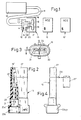
- 10 denotes a schematically indicated ignition control device for a gasoline engine, z. B. a motor vehicle.
- the ignition control device 10 is connected to a plug housing 12 via a cable loop 11.
- Ignition control device 10 and cable loop 11 form an open partial circuit, the open contact points of which are numbered 13 and 14 in FIG. 1 are located inside the connector housing 12.
- the contact points 13, 14 can, for. B. be designed as sockets.
- a connector, generally designated 15, is provided, in the interior of which a first partial circuit 16 and a second partial circuit 17 are arranged.
- Each partial circuit - 16 or 17 - is characterized by an electrical resistance - 18 or 19 -.
- the partial circuits 16, 17 are arranged in parallel in the connector 15. They form a total of three connections 20, 21 and 22, which open into a recess 23 of the plug body and z. B. can be designed as plug contacts.
- each of the sub-circuits 16, 17 has a separate connection 20 and 21, which is assigned only to the respective sub-circuit.
- the two sub-circuits 16, 17 have a connection 22 that is common to them. This makes the first sub-circuit 16 the electrical connections 21, 22 and the second sub-circuit 17 the electrical connections 20, 22 assigned.
- the connector 15 is plugged onto the connector housing 12, the connector housing 12 engaging with a projection 24 in the recess 23 of the connector body.
- the connections 13, 14 of the plug housing 12 are in electrical contact with the mating connections 21, 22 of the plug 15.
- the partial circuit of the ignition control device 10 and the cable loop 11 is thus closed by the first partial circuit 16 of the plug 15.
- the ignition setting implemented in this way on the ignition control device 10 is thus determined by the first plug subcircuit 16 or by its resistor 18. This is one of two possible positions of the plug 15 relative to the plug housing 12.
- the second plug position can be achieved by simply plugging the plug 15 through 180 °.
- the electrical connections 13, 14 of the plug housing 12 would then be in electrical contact with the two other mating connections - 20, 22 - of the plug 15.
- the ignition setting on the ignition control device 10 would be determined by the second partial circuit 17 or the second resistor 19 of the plug 15.
- the first connector position shown in FIG. 1 should correspond to an ignition setting for the greatest possible octane number of the fuel to be used.
- this octane number can be marked on the outside of the connector 15 by the number 8, which then - together with the number 9 marked on the connector housing - in the relevant connector position the octane number "98" which is decisive for the fuel to be used. results.
- a further marking (the number 5) can be provided, which in the second connector position - together with the number 9 marked on the connector housing 12 - again results in an octane number.
- this is the octane number "95”.
- a fuel with the (comparatively low) octane number of "95” e.g. B. unleaded premium gasoline can use.
- FIG. 1 now shows an embodiment for a practical embodiment of a connector which is only indicated schematically in FIG. 1 and is designated by 15.
- the plug 15 has a plug body 25 which, for. B. can be made as a molded plastic part.
- the three electrical connections 20, 21 and 22 already mentioned in connection with the description of FIG. 1 can be seen in particular from FIG. 3. 2, they are designed as plug contacts.
- the plug contacts 20, 21 and 22 protrude into a stepped recess 23a, 23b at the front end of the plug 15, where they are electrically connected to the corresponding mating contacts 13, 14 (FIG. 1) of the plug housing 12 (not shown in FIGS. 2-4) Can come in contact.
- FIG. 1 In a modification of the octane number combinations shown in FIG.
- the plug body bears the number 5 on the front and the number 1 on the rear (not shown). In cooperation with the number 9 marked on the plug housing, this corresponds to a plug position for activating the octane number "95" or "91" assigned ignition map on the ignition control unit when refueling the vehicle with unleaded premium gasoline or leaded or unleaded regular gasoline.
- a cover cap 27 ⁇ which is molded onto the plug body at 26 or is ultrasonically welded on serves as cover 27 for the assembly opening of the plug body after the plug contacts and the resistance bridges have been installed (16 ⁇ , 18 ⁇ or 17 ⁇ , 19 ⁇ , not visible).
Landscapes
- Engineering & Computer Science (AREA)
- Chemical & Material Sciences (AREA)
- Combustion & Propulsion (AREA)
- Mechanical Engineering (AREA)
- General Engineering & Computer Science (AREA)
- Signal Processing (AREA)
- Details Of Connecting Devices For Male And Female Coupling (AREA)
- Combined Controls Of Internal Combustion Engines (AREA)
Applications Claiming Priority (2)
| Application Number | Priority Date | Filing Date | Title |
|---|---|---|---|
| DE3609850 | 1986-03-22 | ||
| DE3609850A DE3609850C1 (de) | 1986-03-22 | 1986-03-22 | Codiervorrichtung fuer Ottomotoren von Kraftfahrzeugen |
Publications (4)
| Publication Number | Publication Date |
|---|---|
| EP0241705A2 true EP0241705A2 (fr) | 1987-10-21 |
| EP0241705A3 EP0241705A3 (en) | 1988-03-23 |
| EP0241705B1 EP0241705B1 (fr) | 1991-10-16 |
| EP0241705B2 EP0241705B2 (fr) | 1995-04-05 |
Family
ID=6297121
Family Applications (1)
| Application Number | Title | Priority Date | Filing Date |
|---|---|---|---|
| EP87103479A Expired - Lifetime EP0241705B2 (fr) | 1986-03-22 | 1987-03-11 | Dispositif de codage pour moteurs à combustion interne de véhicules |
Country Status (2)
| Country | Link |
|---|---|
| EP (1) | EP0241705B2 (fr) |
| DE (2) | DE3609850C1 (fr) |
Families Citing this family (5)
| Publication number | Priority date | Publication date | Assignee | Title |
|---|---|---|---|---|
| DE3731701C1 (en) * | 1986-03-22 | 1988-12-29 | Opel Adam Ag | Coding device for spark ignition engines of motor vehicles |
| DE3726313A1 (de) * | 1986-03-22 | 1989-02-16 | Opel Adam Ag | Codiervorrichtung fuer ottomotoren von kraftfahrzeugen |
| FR2659490A1 (fr) * | 1990-03-12 | 1991-09-13 | Electronique Pratique Ste Nle | Boitier porte-fusibles programmable, et dispositif d'alarme utilisant un tel boitier. |
| DE4126373C2 (de) * | 1991-08-09 | 1995-11-02 | Bayerische Motoren Werke Ag | Steuergerät für Kraftfahrzeuge mit zwei möglichen Arbeitsweisen |
| DE10333651B4 (de) * | 2003-07-24 | 2005-10-06 | Bayerische Motoren Werke Ag | Schaltungsanordnung für Kraftfahrzeuge |
Family Cites Families (5)
| Publication number | Priority date | Publication date | Assignee | Title |
|---|---|---|---|---|
| DE679499C (de) * | 1937-11-02 | 1939-08-07 | Bosch Gmbh Robert | Zuendverteiler |
| US3659574A (en) * | 1970-04-13 | 1972-05-02 | East Ohio Gas Co The | Natural gas powered engine |
| US4013050A (en) * | 1975-02-28 | 1977-03-22 | Motorola, Inc. | Ignition system for a multifueled engine |
| US4399780A (en) * | 1981-10-23 | 1983-08-23 | Outboard Marine Corporation | Spark advance control mechanism for dual fuel engine |
| DE3144733A1 (de) * | 1981-11-11 | 1983-08-04 | Dr.Ing.H.C. F. Porsche Ag, 7000 Stuttgart | "brennkraftmaschine der otto-bauart mit einem zuendverteiler und einem elektronischen zuendzeitpunkt-kennfeldspeicher" |
-
1986
- 1986-03-22 DE DE3609850A patent/DE3609850C1/de not_active Expired
-
1987
- 1987-03-11 EP EP87103479A patent/EP0241705B2/fr not_active Expired - Lifetime
- 1987-03-11 DE DE8787103479T patent/DE3773725D1/de not_active Expired - Lifetime
Also Published As
| Publication number | Publication date |
|---|---|
| DE3609850C1 (de) | 1987-09-10 |
| EP0241705B2 (fr) | 1995-04-05 |
| EP0241705A3 (en) | 1988-03-23 |
| EP0241705B1 (fr) | 1991-10-16 |
| DE3773725D1 (de) | 1991-11-21 |
Similar Documents
| Publication | Publication Date | Title |
|---|---|---|
| EP0181534A1 (fr) | Dispositif pour une automobile | |
| DE19801526A1 (de) | Kombinationsschaltvorrichtung | |
| DE102020128580A1 (de) | Elektromotorisch angetriebene Verriegelungseinrichtung | |
| DE69721633T2 (de) | Montagestruktur eines Schalters | |
| DE3034424A1 (de) | Sicherheitsschaltung fuer eine elektronische drosselklappenregelung von brennkraftmaschinen | |
| EP0241705B1 (fr) | Dispositif de codage pour moteurs à combustion interne de véhicules | |
| DE3333138A1 (de) | Schalterleiste an einem armaturenbrett fuer fahrzeuge, insbesondere kraftfahrzeuge | |
| DE60108386T2 (de) | Elektrischer kurzschlussverbinder | |
| DE19936848C1 (de) | Kurzschlußkontaktträger für einen Steckansatz eines Zündersockels | |
| DE3416495A1 (de) | Potentiometer | |
| DE9212062U1 (de) | Wipptaster | |
| DE3050942C2 (de) | Elektrische Schalteinrichtung | |
| DE3113509A1 (de) | Unterbringungssystem zur aufnahme einer elektrischen anschlussgruppe fuer bedienungseinrichtungen und/oder instrumente und/oder zusatzeinrichtungen eines fahrzeugs | |
| DE102024103556A1 (de) | Überspannungsschutz-einrichtung | |
| EP1330883A1 (fr) | Appareil electronique | |
| EP1986281B1 (fr) | Procédé de fabrication d'une liaison électrique conductrice | |
| DE337290C (de) | Steckerschalter, bei welchem im Dosenkoerper eine Schaltvorrichtung angeordnet ist, welche durch Verdrehen des eingefuehrten Steckers den Stromschluss bewirkt | |
| DD295295A5 (de) | Verteilerleiste fuer telekommunikationsanlagen mit trennkontakten | |
| DE2809853B2 (fr) | ||
| DE60011847T2 (de) | Aus einer Blattfeder und ihrer Halterung bestehende Einheit für einen Schnappschalter und Herstellungsverfahren | |
| DE2814821A1 (de) | Vorrichtung zur aufnahme der betriebsschalter eines kraftfahrzeuges | |
| DE19500288A1 (de) | Anzeigeeinrichtung | |
| DE3541884A1 (de) | Verfahren und schaltungsanordnung zur ansteuerung von treiberstufen fuer funktionen von kraftfahrzeug-verbrennungsmotoren, insbesondere fuer die kraftstoffeinspritzung oder zuendung | |
| DE8235148U1 (de) | Mechanische Steuerungseinrichtung für elektrische Kontaktanordnungen, insbesondere für schaltende Zeitmeßgeräte | |
| DE19804453A1 (de) | Schwimmend gelagerter Verbinder zum Verbinden elektrischer Baugruppen |
Legal Events
| Date | Code | Title | Description |
|---|---|---|---|
| PUAI | Public reference made under article 153(3) epc to a published international application that has entered the european phase |
Free format text: ORIGINAL CODE: 0009012 |
|
| AK | Designated contracting states |
Kind code of ref document: A2 Designated state(s): DE FR GB IT SE |
|
| PUAL | Search report despatched |
Free format text: ORIGINAL CODE: 0009013 |
|
| RHK1 | Main classification (correction) |
Ipc: F02P 5/15 |
|
| AK | Designated contracting states |
Kind code of ref document: A3 Designated state(s): DE FR GB IT SE |
|
| 17P | Request for examination filed |
Effective date: 19880719 |
|
| 17Q | First examination report despatched |
Effective date: 19910311 |
|
| ITF | It: translation for a ep patent filed | ||
| GRAA | (expected) grant |
Free format text: ORIGINAL CODE: 0009210 |
|
| AK | Designated contracting states |
Kind code of ref document: B1 Designated state(s): DE FR GB IT SE |
|
| ET | Fr: translation filed | ||
| GBT | Gb: translation of ep patent filed (gb section 77(6)(a)/1977) | ||
| REF | Corresponds to: |
Ref document number: 3773725 Country of ref document: DE Date of ref document: 19911121 |
|
| PLBI | Opposition filed |
Free format text: ORIGINAL CODE: 0009260 |
|
| 26 | Opposition filed |
Opponent name: ROBERT BOSCH GMBH Effective date: 19920716 |
|
| EAL | Se: european patent in force in sweden |
Ref document number: 87103479.9 |
|
| PUAH | Patent maintained in amended form |
Free format text: ORIGINAL CODE: 0009272 |
|
| STAA | Information on the status of an ep patent application or granted ep patent |
Free format text: STATUS: PATENT MAINTAINED AS AMENDED |
|
| ITF | It: translation for a ep patent filed | ||
| 27A | Patent maintained in amended form |
Effective date: 19950405 |
|
| AK | Designated contracting states |
Kind code of ref document: B2 Designated state(s): DE FR GB IT SE |
|
| GBTA | Gb: translation of amended ep patent filed (gb section 77(6)(b)/1977) |
Effective date: 19950412 |
|
| ET3 | Fr: translation filed ** decision concerning opposition | ||
| REG | Reference to a national code |
Ref country code: GB Ref legal event code: 746 Effective date: 19991224 |
|
| REG | Reference to a national code |
Ref country code: FR Ref legal event code: D6 |
|
| PGFP | Annual fee paid to national office [announced via postgrant information from national office to epo] |
Ref country code: GB Payment date: 20010302 Year of fee payment: 15 |
|
| PGFP | Annual fee paid to national office [announced via postgrant information from national office to epo] |
Ref country code: FR Payment date: 20010321 Year of fee payment: 15 |
|
| PGFP | Annual fee paid to national office [announced via postgrant information from national office to epo] |
Ref country code: SE Payment date: 20010326 Year of fee payment: 15 |
|
| PGFP | Annual fee paid to national office [announced via postgrant information from national office to epo] |
Ref country code: DE Payment date: 20010515 Year of fee payment: 15 |
|
| REG | Reference to a national code |
Ref country code: GB Ref legal event code: IF02 |
|
| PG25 | Lapsed in a contracting state [announced via postgrant information from national office to epo] |
Ref country code: GB Free format text: LAPSE BECAUSE OF NON-PAYMENT OF DUE FEES Effective date: 20020311 |
|
| PG25 | Lapsed in a contracting state [announced via postgrant information from national office to epo] |
Ref country code: SE Free format text: LAPSE BECAUSE OF NON-PAYMENT OF DUE FEES Effective date: 20020312 |
|
| PG25 | Lapsed in a contracting state [announced via postgrant information from national office to epo] |
Ref country code: DE Free format text: LAPSE BECAUSE OF NON-PAYMENT OF DUE FEES Effective date: 20021001 |
|
| EUG | Se: european patent has lapsed |
Ref document number: 87103479.9 |
|
| GBPC | Gb: european patent ceased through non-payment of renewal fee |
Effective date: 20020311 |
|
| PG25 | Lapsed in a contracting state [announced via postgrant information from national office to epo] |
Ref country code: FR Free format text: LAPSE BECAUSE OF NON-PAYMENT OF DUE FEES Effective date: 20021129 |
|
| REG | Reference to a national code |
Ref country code: FR Ref legal event code: ST |
|
| PG25 | Lapsed in a contracting state [announced via postgrant information from national office to epo] |
Ref country code: IT Free format text: LAPSE BECAUSE OF NON-PAYMENT OF DUE FEES Effective date: 20050311 |