EP0241689A2 - Allumeur à retard pyrotechnique - Google Patents
Allumeur à retard pyrotechnique Download PDFInfo
- Publication number
- EP0241689A2 EP0241689A2 EP87102986A EP87102986A EP0241689A2 EP 0241689 A2 EP0241689 A2 EP 0241689A2 EP 87102986 A EP87102986 A EP 87102986A EP 87102986 A EP87102986 A EP 87102986A EP 0241689 A2 EP0241689 A2 EP 0241689A2
- Authority
- EP
- European Patent Office
- Prior art keywords
- detonator
- protection
- breakdown protection
- detonator according
- ignition
- Prior art date
- Legal status (The legal status is an assumption and is not a legal conclusion. Google has not performed a legal analysis and makes no representation as to the accuracy of the status listed.)
- Withdrawn
Links
- 239000003999 initiator Substances 0.000 title 1
- 230000015556 catabolic process Effects 0.000 claims abstract description 33
- 239000007787 solid Substances 0.000 claims abstract description 13
- 239000002360 explosive Substances 0.000 claims description 13
- 239000000463 material Substances 0.000 claims description 9
- 239000004033 plastic Substances 0.000 claims description 7
- 238000000354 decomposition reaction Methods 0.000 claims description 5
- 238000006243 chemical reaction Methods 0.000 claims description 4
- 229910052751 metal Inorganic materials 0.000 claims description 4
- 239000002184 metal Substances 0.000 claims description 4
- 239000002245 particle Substances 0.000 claims description 4
- RNFJDJUURJAICM-UHFFFAOYSA-N 2,2,4,4,6,6-hexaphenoxy-1,3,5-triaza-2$l^{5},4$l^{5},6$l^{5}-triphosphacyclohexa-1,3,5-triene Chemical compound N=1P(OC=2C=CC=CC=2)(OC=2C=CC=CC=2)=NP(OC=2C=CC=CC=2)(OC=2C=CC=CC=2)=NP=1(OC=1C=CC=CC=1)OC1=CC=CC=C1 RNFJDJUURJAICM-UHFFFAOYSA-N 0.000 claims 1
- 239000003063 flame retardant Substances 0.000 claims 1
- 239000004952 Polyamide Substances 0.000 description 3
- 230000005540 biological transmission Effects 0.000 description 3
- 239000011888 foil Substances 0.000 description 3
- 229920002647 polyamide Polymers 0.000 description 3
- 229920002160 Celluloid Polymers 0.000 description 2
- 238000010304 firing Methods 0.000 description 2
- 229910001385 heavy metal Inorganic materials 0.000 description 2
- LWNCNSOPVUCKJL-UHFFFAOYSA-N [Mg].[P] Chemical compound [Mg].[P] LWNCNSOPVUCKJL-UHFFFAOYSA-N 0.000 description 1
- MKPXGEVFQSIKGE-UHFFFAOYSA-N [Mg].[Si] Chemical compound [Mg].[Si] MKPXGEVFQSIKGE-UHFFFAOYSA-N 0.000 description 1
- 230000003321 amplification Effects 0.000 description 1
- 238000002485 combustion reaction Methods 0.000 description 1
- 230000007613 environmental effect Effects 0.000 description 1
- 230000000977 initiatory effect Effects 0.000 description 1
- 239000002650 laminated plastic Substances 0.000 description 1
- 238000004519 manufacturing process Methods 0.000 description 1
- 239000000155 melt Substances 0.000 description 1
- 238000003199 nucleic acid amplification method Methods 0.000 description 1
- 238000007493 shaping process Methods 0.000 description 1
- 239000000126 substance Substances 0.000 description 1
- 238000005979 thermal decomposition reaction Methods 0.000 description 1
Images

Classifications
-
- F—MECHANICAL ENGINEERING; LIGHTING; HEATING; WEAPONS; BLASTING
- F42—AMMUNITION; BLASTING
- F42C—AMMUNITION FUZES; ARMING OR SAFETY MEANS THEREFOR
- F42C15/00—Arming-means in fuzes; Safety means for preventing premature detonation of fuzes or charges
- F42C15/34—Arming-means in fuzes; Safety means for preventing premature detonation of fuzes or charges wherein the safety or arming action is effected by a blocking-member in the pyrotechnic or explosive train between primer and main charge
-
- F—MECHANICAL ENGINEERING; LIGHTING; HEATING; WEAPONS; BLASTING
- F42—AMMUNITION; BLASTING
- F42B—EXPLOSIVE CHARGES, e.g. FOR BLASTING, FIREWORKS, AMMUNITION
- F42B3/00—Blasting cartridges, i.e. case and explosive
- F42B3/10—Initiators therefor
- F42B3/16—Pyrotechnic delay initiators
Definitions
- the invention relates to a detonator with a pyrotechnic deceleration charge arranged between the primer and explosive charge or initial explosive charge and at least one puncture protection device which prevents an ignition transfer from the primer to the explosive charge or initial explosive charge in the complete or partial absence of the delay charge.
- the currently known and in use breakdown protection in pyrotechnic delay elements have the disadvantage that when the fuse element consisting of a coated heavy metal foil bursts or melts, the further course of the ignition channel can be completely or partially covered or relocated by the resulting particles, thereby making it reliable Ignition transfer to the initial explosive charge, e.g. on the detonator of a hand grenade detonator. Furthermore, when using coated heavy metal foils, a not insignificant environmental impact can be determined.
- the breakdown protection consists of a flammable or thermally decomposable solid which burns to a large extent without solid residues or which decomposes thermally.
- the breakdown protection according to the invention in this sense consists of one - but only in connection with the Burn-up of the delay set - material involved in the ignition transmission "active".
- the requirement that the breakdown protection should prevent the ignition transmission from the primer to the explosive charge or initial explosive charge in the absence of the delay set can be met in such an "active" material in that the ignition or decomposition temperature of the solid of the breakdown protection above that of the ignition beam of the Primer at the location of the breakdown protection gas or particle temperature is, but below the reaction temperature generated by the burned-down delay set.
- reaction temperatures of approximately 1300 ° C. occur due to the combustion of the delay kit.
- the particles of the primer In the absence of a delay set, the particles of the primer would hit the puncture protection, which was about 30 to 35 mm away, at about 500 to 600 ° C.
- a solid would advantageously be used as material for the puncture protection, the ignition or decomposition temperature of which is above 600 ° C. but below 1300 ° C.
- the breakdown protection according to the invention can consist, for example, of a film made of plastic, such as, for example, of polyamide or of a laminate of plastic, for example with a layer of polyamide and a layer of celluloid, the polyamide predominantly having a buffer function and the celluloid the actual "active" material represents.
- plastic such as, for example, of polyamide or of a laminate of plastic
- metal foils can also be used, provided they are flammable and burn essentially without solid residues.
- Metal-plastic laminates can also be used.
- Another option would be to use heavy flammable pyrotechnic material, for example of coruscative sets for protection against breakdown, optionally in combination with metal and / or plastic layers.
- the desired ignition transmission performance of the breakdown protection can be positively influenced by special shaping of the material of the breakdown protection, e.g. through cone, dome or hemisphere shape, as a solid or hollow body.
- the breakdown protection can, as usual, be arranged between the lowest subsection of the delay set and the detonator, and / or also between subsets of the delay set.
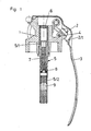
- the grenade detonator shown consists of a detonator head 1, a spring-loaded racket 2 which is pivotably mounted on the fuse head 1, a safety bracket 3 which holds the racket 2 in a cocked position before the hand grenade is ejected, the safety bracket 3 being secured with the aid of a cotter pin 4 Position on detonator head 1 is held.
- the ignition tube (labeled 5 overall) is screwed into the interior of the detonator head 1. It contains the primer 6, three subsets of the delay set 7, the breakdown protection 8 and the multilayer detonator charge 9 from top to bottom. The breakdown protection is close to the lower end of the delay set 7, but with a (greater) distance above the detonator charge 9 is arranged.
- the breakdown protection 8 is conical and consists e.g. made of plastic.
- the delay set 7 is normally initiated by the primer 6 and, after the predetermined delay time has elapsed, the conical puncture protection 8 is activated, which in turn forwards the ignition beam to the detonator 9.
- the ignition beam of the primer 4 strikes the breakdown protection 8.
- a solid, e.g. Plastic used, the ignition temperature (decomposition temperature) is high enough that the ignition energy is not sufficient to activate the material of the breakdown device 8. The ignition beam is interrupted and initiation of the detonator 9 is prevented.
- Fig. 2 differs from Fig. 1 in that a full body, e.g. Grafting, made of "active" material.
- the advantage is the additional amplification of the ignition beam.
- the breakdown protection 8 is arranged between two partial sets (press fractions) 7/1, 7/2 of the delay set 7, the lower 7/2 facing the detonator being smaller. If the delay element is properly manufactured, the firing beam of the primer 6 will initiate the subset 7/1, which subsequently forwards the firing beam to the subset 7/2. If subset 7/1 is now missing, the ignition beam from the primer 6 is not sufficient to activate the breakdown protection 8. The ignition is interrupted, unwanted ignition is thus prevented here too.
- the ignition tube in this case consists of two sub-tubes 5/1, 5/2 in the area of the delay set, the sub-tube 5/2 being filled with the sub-set 7/2 of the delay charge first, whereupon the breakdown protection 8 is placed and the sub-tube 5/2 is screwed to the partial tube 5/1. Only then is the subset 7/1 filled.
- a second breakdown protection can also be arranged under the lower subset 7/2 (approximately as in FIG. 1 or 2).
- the variant according to FIG. 3 shows the use of a coruscative set as a breakdown protection 8.
- Coruscative consisting of pairs of substances, e.g. made of magnesium silicon, magnesium phosphorus or the like.
- the coruscative set is molded into the ignition tube 5 in a separate operation before the ignition tube reaches the filling station of the delay set 7.
- the puncture protection device 8 can also consist of a combination of a corusive set with a film, a plug or the like made of plastic and / or metal.
- the exemplary embodiments show detonators for hand grenades.
- the puncture protection according to the invention can also be used with detonators for other types of ammunition and also in non-military fields.
Landscapes
- Engineering & Computer Science (AREA)
- General Engineering & Computer Science (AREA)
- Air Bags (AREA)
Applications Claiming Priority (2)
| Application Number | Priority Date | Filing Date | Title |
|---|---|---|---|
| AT568/86 | 1986-03-06 | ||
| AT56886 | 1986-03-06 |
Publications (2)
| Publication Number | Publication Date |
|---|---|
| EP0241689A2 true EP0241689A2 (fr) | 1987-10-21 |
| EP0241689A3 EP0241689A3 (fr) | 1989-05-10 |
Family
ID=3494056
Family Applications (1)
| Application Number | Title | Priority Date | Filing Date |
|---|---|---|---|
| EP87102986A Withdrawn EP0241689A3 (fr) | 1986-03-06 | 1987-03-03 | Allumeur à retard pyrotechnique |
Country Status (1)
| Country | Link |
|---|---|
| EP (1) | EP0241689A3 (fr) |
Cited By (2)
| Publication number | Priority date | Publication date | Assignee | Title |
|---|---|---|---|---|
| EP0491530A3 (en) * | 1990-12-16 | 1992-12-30 | Israel Military Industries Ltd. | Delay detonator |
| RU2160395C2 (ru) * | 1998-10-20 | 2000-12-10 | Российский Федеральный Ядерный Центр - Всероссийский Научно-Исследовательский Институт Экспериментальной Физики | Пробойник пиромеханический |
Family Cites Families (2)
| Publication number | Priority date | Publication date | Assignee | Title |
|---|---|---|---|---|
| DE2004619A1 (en) * | 1970-02-03 | 1971-08-19 | Dynamit Nobel Ag, 5210 Troisdorf | Pyrotechnic time fuse |
| AT364286B (de) * | 1979-08-01 | 1981-10-12 | Oregon Ets Patentverwertung | Verfahren zur herstellung eines beidseitig offenen zuendroehrchens fuer einen handgranatenzuender |
-
1987
- 1987-03-03 EP EP87102986A patent/EP0241689A3/fr not_active Withdrawn
Cited By (2)
| Publication number | Priority date | Publication date | Assignee | Title |
|---|---|---|---|---|
| EP0491530A3 (en) * | 1990-12-16 | 1992-12-30 | Israel Military Industries Ltd. | Delay detonator |
| RU2160395C2 (ru) * | 1998-10-20 | 2000-12-10 | Российский Федеральный Ядерный Центр - Всероссийский Научно-Исследовательский Институт Экспериментальной Физики | Пробойник пиромеханический |
Also Published As
| Publication number | Publication date |
|---|---|
| EP0241689A3 (fr) | 1989-05-10 |
Similar Documents
| Publication | Publication Date | Title |
|---|---|---|
| EP0164732B1 (fr) | Dispositif de génération d'un nuage fausse cible, notamment nuage infrarouge | |
| WO1986005265A1 (fr) | Munition a cartouche | |
| DE2105295C1 (de) | Pulverkörper für hülsenlose Munition | |
| DE2908116A1 (de) | Nebeldose | |
| DE19548436C1 (de) | Schnellnebelhandgranate | |
| DE106263T1 (de) | Panzerbrechendes sprenggeschoss versehen mit einer treibladungshuelse. | |
| DE1240760B (de) | Panzerbrandgeschoss | |
| EP0763705A2 (fr) | Projectile secondaire pour projectile du type tandem | |
| DE2936861C2 (de) | Kartusche zum Ausstreuen von Scheinzielmaterial, insbesondere aus einem Luftfahrzeug | |
| DE2552950A1 (de) | Brandmunition | |
| DE2655674C3 (de) | Brandkörper mit Verankerungsspitze | |
| EP1514072B1 (fr) | Corps fumigene | |
| DE102009030871B4 (de) | Verbrennbarer Wirkmassencontainer | |
| EP0241689A2 (fr) | Allumeur à retard pyrotechnique | |
| DE2726945A1 (de) | Ueb-geschoss fuer moerser o.dgl. | |
| DE2932921C2 (de) | Kontaktkopf für aus elektrisch betätigbaren Wurfbechern verschießbare Wurfkörper | |
| WO1981000450A1 (fr) | Procede de fabrication d'un petit tube d'allumage ouvert a ses deux extremites, pour fusee de grenade a main | |
| DE19830134B4 (de) | Leuchtfackel für einen Hubschrauber und Verfahren zum Erzeugen einer Köderspur | |
| DE1578208A1 (de) | Geschosspatrone mit Zuendkapsel | |
| CH85741A (de) | Geschoss. | |
| DE8136383U1 (de) | Granate | |
| DE268324C (fr) | ||
| DE307160C (fr) | ||
| DE264476C (fr) | ||
| DE1936973A1 (de) | Verfahren und Vorrichtung zum Abfeuern von Geschossen aus Rohren und Laeufen |
Legal Events
| Date | Code | Title | Description |
|---|---|---|---|
| PUAI | Public reference made under article 153(3) epc to a published international application that has entered the european phase |
Free format text: ORIGINAL CODE: 0009012 |
|
| AK | Designated contracting states |
Kind code of ref document: A2 Designated state(s): BE DE ES FR GB GR IT NL SE |
|
| PUAL | Search report despatched |
Free format text: ORIGINAL CODE: 0009013 |
|
| AK | Designated contracting states |
Kind code of ref document: A3 Designated state(s): BE DE ES FR GB GR IT NL SE |
|
| 17P | Request for examination filed |
Effective date: 19891031 |
|
| 17Q | First examination report despatched |
Effective date: 19901122 |
|
| STAA | Information on the status of an ep patent application or granted ep patent |
Free format text: STATUS: THE APPLICATION IS DEEMED TO BE WITHDRAWN |
|
| 18D | Application deemed to be withdrawn |
Effective date: 19921001 |
|
| RIN1 | Information on inventor provided before grant (corrected) |
Inventor name: DORAZIL, OTTO |