EP0241674A1 - Hängeelement für Kulissendecken - Google Patents
Hängeelement für Kulissendecken Download PDFInfo
- Publication number
- EP0241674A1 EP0241674A1 EP87102308A EP87102308A EP0241674A1 EP 0241674 A1 EP0241674 A1 EP 0241674A1 EP 87102308 A EP87102308 A EP 87102308A EP 87102308 A EP87102308 A EP 87102308A EP 0241674 A1 EP0241674 A1 EP 0241674A1
- Authority
- EP
- European Patent Office
- Prior art keywords
- plate
- shaped
- element according
- metal
- profile
- Prior art date
- Legal status (The legal status is an assumption and is not a legal conclusion. Google has not performed a legal analysis and makes no representation as to the accuracy of the status listed.)
- Granted
Links
- 229910052751 metal Inorganic materials 0.000 claims abstract description 28
- 239000002184 metal Substances 0.000 claims abstract description 28
- 239000011148 porous material Substances 0.000 claims description 2
- 238000005452 bending Methods 0.000 abstract description 4
- 239000011888 foil Substances 0.000 abstract 2
- 230000005484 gravity Effects 0.000 abstract 1
- 238000010521 absorption reaction Methods 0.000 description 4
- 239000000725 suspension Substances 0.000 description 3
- 229910052782 aluminium Inorganic materials 0.000 description 1
- XAGFODPZIPBFFR-UHFFFAOYSA-N aluminium Chemical compound [Al] XAGFODPZIPBFFR-UHFFFAOYSA-N 0.000 description 1
- 230000015572 biosynthetic process Effects 0.000 description 1
- 230000002349 favourable effect Effects 0.000 description 1
- 239000006260 foam Substances 0.000 description 1
- 239000000463 material Substances 0.000 description 1
- 239000002557 mineral fiber Substances 0.000 description 1
- 239000011490 mineral wool Substances 0.000 description 1
- 238000012986 modification Methods 0.000 description 1
- 230000004048 modification Effects 0.000 description 1
- 238000007493 shaping process Methods 0.000 description 1
Images
Classifications
-
- E—FIXED CONSTRUCTIONS
- E04—BUILDING
- E04B—GENERAL BUILDING CONSTRUCTIONS; WALLS, e.g. PARTITIONS; ROOFS; FLOORS; CEILINGS; INSULATION OR OTHER PROTECTION OF BUILDINGS
- E04B9/00—Ceilings; Construction of ceilings, e.g. false ceilings; Ceiling construction with regard to insulation
- E04B9/34—Grid-like or open-work ceilings, e.g. lattice type box-like modules, acoustic baffles
-
- E—FIXED CONSTRUCTIONS
- E04—BUILDING
- E04B—GENERAL BUILDING CONSTRUCTIONS; WALLS, e.g. PARTITIONS; ROOFS; FLOORS; CEILINGS; INSULATION OR OTHER PROTECTION OF BUILDINGS
- E04B9/00—Ceilings; Construction of ceilings, e.g. false ceilings; Ceiling construction with regard to insulation
- E04B9/001—Ceilings; Construction of ceilings, e.g. false ceilings; Ceiling construction with regard to insulation characterised by provisions for heat or sound insulation
Definitions
- the invention relates to a hanging element for backdrop ceilings with two plate-shaped bodies, which form the two side surfaces of the element, from sound-absorbing, porous materials, e.g. soft synthetic foam or rockwool, with a significantly thinner, preferably film or sheet-like plate with a significantly higher specific weight than these bodies arranged between these bodies and in the area of the upper edge of the element transverse metal profiles for holding the body are provided.
- sound-absorbing, porous materials e.g. soft synthetic foam or rockwool
- the invention is essentially based on the object to design the above hanging elements so that they get a longer length and can therefore be assembled more easily.
- the aim continues to be low production costs for the hanging elements, which have excellent sound absorption properties.
- the metal profiles of the upper edge of the hanging elements on the one hand and the plate mentioned form a cross-section which is at least approximately T-shaped in bending cross-section, the plate being connected to the metal profiles in a tensile manner and the plate running approximately vertically, while those located on the top of the hanging element Metal profiles extend practically horizontally.
- a T-beam is thus formed, the cross bar of which is horizontal and the other web of which - arranged in the center of the cross bar - is arranged vertically.
- the plate located between the lateral sound-absorbing bodies is used on the one hand as a strength-imparting component and on the other hand as an important component for sound absorption.
- the strength of the T-beam is also ensured by the metal profiles mentioned, which extend transversely to the hanging element and at the same time ensure that the lateral bodies are held.
- the hanging elements enables spans of up to approximately 15 m without fear of undesired deformations and distortions.
- the plate mentioned is given a favorable shape in the interior of the hanging element. It should preferably not be flat, but - when viewed from above or in a horizontal section - wavy, zigzag od.
- the waves can also be square, rectangular or trapezoidal.
- the plates designed in this way are then firmly connected locally to the metal profiles above by means of rivets or the like in order to be able to produce a T-beam.
- An approximately U-shaped profile made of metal can also be provided at the lower end, which encloses the lower end of the plate shaped in the aforementioned sense. This profile is also expediently firmly connected to the plate, for example by riveting.
- a modification of the hanging element according to the invention provides for a special design of a metal profile located at the lower edge of the hanging element.
- This can be designed on the basis of the invention in such a way that it forms a double T profile together with the aforementioned T profile, the metal profile below also being designed such that it extends predominantly horizontally.
- this profile is also connected to the centrally arranged plate so that it cannot slide and pull. Riveting is also an option here, which is particularly useful for the thin-walled aluminum materials used.
- Hanging elements of this type are used to reduce the sound level e.g. used in production rooms, they are hung as a backdrop under the ceiling of the room, which can be used for wires, ropes or the like, which attack the elements at the top.
- the elements are therefore not underpinned or supported from below, because this is impossible with an arrangement under a ceiling.
- the hanging elements must be light, but at the same time rigid, so that they can be suspended and assembled over longer lengths in a self-supporting manner.
- An essential component of these elements are predominantly laterally arranged plate-shaped bodies 1, which can also have horizontal sections 2 located at the top and sections 3 arranged at the bottom, wherein shaping is possible by angling a larger plate.
- These bodies 1 are preferably made of mineral fibers, which have laminated cover layers to desired upper to be able to maintain surface properties.
- a profile 4 made of light metal or the like is provided at the upper edge of the hanging element, to which the suspension elements, which are not shown in more detail, normally also act .
- the profile 4 is formed by an overhead plate 5, which is equipped with two spaced apart legs 6, which are directed downwards.
- a sheet 7 made of light metal or the like engages in the space between the two legs 6, which is designed in a wave shape and, as shown in FIG. 2, has successive trapezoidal press-ins 8 which form laterally alternating planar sections 9, which on the inside of the legs 6 abut and also come to rest at the lower end on the upward legs 10 of a continuous, uninterrupted over the length of the hanging elements.
- the sections 9 are arranged both on the top and bottom of the profiles 4 and 11 by rivets 12 push and pull resistant.
- the sections 2 lie against the inside of the profile 4 and the sections 3 below against the web of the profile 11. So that the laterally arranged body 1 are at a distance from the centrally arranged sheet 7.
- This design leads to very good sound absorption properties, at the same time the profiles 4 and 11 together with the profiled sheet 7 form a T-beam, which the hanging element a good Bending rigidity against bending gives and spans of 15 m.
- the width of the plate 5 also be kept so low that only part of the sections 2 is covered. So the side edges of the plate 5 can also end at x.
- a sinusoidally shaped plate 7 according to FIG. 3 can also be used. It is appropriate to rigidly connect the adjacent metal parts at the top and bottom.
- a light metal profile is also provided at the bottom of the hanging element, which is designed in accordance with the profile 4, but additionally has edges 13 which are angled laterally upwards in order to be able to hold the body 1 better. Since the sheet 7 is in turn firmly connected to the profiles 4 at both the lower and the upper edge, a double-T beam results.
- Fig. 5 also shows a double-T beam with the profiles 4 and the sheet 7 together with only laterally arranged sound absorbing plates in the form of the body 1st
- the embodiment according to FIG. 6 shows a modified version for the lower edge of the hanging elements.
- the profile 11 according to FIG. 1 also has a t-shaped projection 14 for receiving the lower sections 3.
- the upper profile 4 has hollow points 15 between the bodies 1 and the sheet metal 7, specifically for the formation of hollow, longitudinal box-like supports.
- These overhead profiles 4 are characterized by increased rigidity in the vertical and horizontal directions.
- the bodies 1 can also be arranged close to the plate 7 and, if necessary, touch it.
Landscapes
- Engineering & Computer Science (AREA)
- Architecture (AREA)
- Physics & Mathematics (AREA)
- Electromagnetism (AREA)
- Civil Engineering (AREA)
- Structural Engineering (AREA)
- Building Environments (AREA)
- Dowels (AREA)
- Silicates, Zeolites, And Molecular Sieves (AREA)
- Supports For Pipes And Cables (AREA)
Abstract
Description
- Die Erfindung betrifft ein Hängeelement für Kulissendecken mit zwei plattenförmigen, die beiden Seitenflächen des Elementes bildenden Körpern aus schallabsorbierenden, porösen Stoffen z.B. weich eingestelltem Kunstschaum oder Steinwolle, wobei zwischen diesen Körpern eine gegenüber diesen Körpern wesentlich dünnere, vorzugsweise folien- oder blechartige Platte mit einem gegenüber den Körpern wesentlich höheren spezifischen Gewicht angeordnet und im Bereich des oberen Randes des Elementes quer zum Element verlaufende Metallprofile zur Halterung der Körper vorgesehen sind.
- Diese Elemente haben sich zwar bewährt, jedoch ist es nicht möglich, sie für grössere Spannweiten zu benutzen ausgehend von der Tatsache, dass die obigen Hängeelemente mittels strangförmiger Befestigungen aufgehängt werden, die oben an den Elementen angreifen. Es versteht sich, dass die Montagearbeiten dann am günstigsten sind und eine Aufhängung im Regelfalle dann einfacher auszuführen ist, wenn die Hängeelemente über eine möglichst grosse Länge verfügen.
- Der Erfindung liegt im wesentlichen die Aufgabe zugrunde, die obigen Hängeelemente so auszubilden, dass sie eine grössere Länge erhalten und demgemäss einfacher montiert werden können. Angestrebt werden weiterhin geringe Gestehungskosten für die Hängeelemente, die über ein ausgezeichnetes Schallabsorptionsvermögen verfügen.
- Zur Lösung dieser Aufgabe bilden die Metallprofile des oberen Randes der Hängeelemente einerseits und die erwähnte Platte einen im Querschnitt zumindest in etwa T-förmigen Biegeträger, wobei die Platte mit den Metallprofilen zugfest verbunden ist und die Platte etwa senkrecht verläuft, während die oben am Hängeelement befindlichen Metallprofile sich praktisch waagerecht erstrecken. Gebildet wird somit ein T-Träger, dessen Quersteg waagerecht und dessen anderer Steg - mittig zum Quersteg angeordnet - senkrecht angeordnet ist. Demgemäss wird die zwischen den seitlichen schallabsorbierenden Körpern befindliche Platte einmal als Festigkeit verleihender Bestandteil,zum anderen aber als für die Schallabsorption wichtiger Bestandteil verwendet. Die Festigkeit des T-Trägers wird zudem sichergestellt durch die erwähnten Metallprofile, die sich quer zum Hängeelement erstrecken und zugleich für eine Halterung der seitlichen Körper Sorge tragen.
- Eine solche Ausführung der Hängeelemente ermöglicht Spannweiten bis etwa 15 m, ohne befürchten zu müssen, dass unerwünschte Verformungen und Verwerfungen eintreten. Darüber hinaus ist es auch zweckmässig, wenn die erwähnte Platte im Inneren des Hängeelementes eine günstige Gestalt erhält. Vorzugsweise soll sie nicht eben, sondern - bie Betrachtung von oben bzw. im waagerechten Schnitt - wellenförmig, zickzackförmig od. dgl. ausgeführt sein, wobei die Wellen auch quadratisch, rechteckig oder trapezförmig ausgeführt sein können. Die so ausgeführten Platten werden dann örtlich mittels Niete od. dgl. fest mit den oben liegenden Metallprofilen verbunden, um so einen T-Träger entstehen lassen zu können. Dabei kann auch am unteren Ende ein etwa u-förmiges Profil aus Metall vorgesehen sein, das das untere Ende der im vorgenannten Sinne geformten Platte umschliesst. Auch dieses Profil wird zweckmässigerweise fest z.B. durch Nieten mit der Platte verbunden.
- Eine Abwandlung des erfindungsgemässen Hängeelementes sieht eine besondere Ausführung eines am unteren Rand des Hängeelementes befindlichen Metallprofils vor. Dies kann aufgrund der Erfindung so gestaltet sein, dass es zusammen mit em vorerwähnten T-Profil ein Doppel-T-Profil bildet, wobei wiederum auch das unten liegende Metallprofil so ausgeführt wird, dass es sich vorwiegend waagerecht erstreckt. Zudem wird auch dieses Profil schiebe- und zugfest mit der mittig angeordneten Platte verbunden. Auch hier kommt eine Nietung in Betracht, was insb. bei den verwendeten dünnwandigen Aluminiumwerkstoffen zweckmässig ist.
- Weitere Einzelheiten der Erfindung werden anhand der Zeichnung erläutert, in der Ausführungsbeispiele der Erfindung dargestellt sind.
- Es zeigen :
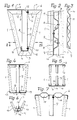
- Fig. 1 ein Hängeelement für eine Kulissendecke im Querschnitt,
- Fig. 2 einen Schnitt nach der Linie II - II von Fig. 1,
- Fig. 3 eine gegenüber Fig. 2 abgewandelte Ausführungsform - der Darstellung gemäss Fig. 2 entsprechend -,
- Fig. 4 und 5 je abgewandelte Hängeelemente im Querschnitt,
- Fig. 6 den unteren Abschnitt eines Hängeelementes im Querschnitt und
- Fig. 7 den oberen Abschnitt eines Hängeelementes im Querschnitt, und zwar in einer weiterhin abgewandelten Ausführungsform.
- Hängeelemente dieser Art werden zur Reduzierung des Schallpegels z.B. in Produktionsräumen benutzt, sie werden als Kulissen unter die Decke der Räume gehängt, wozu Drähte, Seile od. dgl. dienen können, die oben an den Elementen angreifen. Die Elemente sind also nicht unterfangen bzw. von unten her unterstützt,weil dies bei einer Anordnung unter einer Decke ausgeschlossen ist. Zudem müssen die Hängeelemente leicht, zugleich aber auch biegesteif sein, um sie freitragend über grössere Längen hinweg aufhängen und montieren zu können.
- Ein wesentlicher Bestandteil dieser Elemente sind vorwiegend seitlich angeordnete plattenförmige Körper 1, die auch oben befindliche waagerechte Abschnitte 2 und unten angeordnete Abschnitte 3 aufweisen können, wobei eine Formgebung durch Abwinkeln einer grösseren Platte möglich ist. Diese Körper 1 bestehen vorzugsweise aus Mineralfasern, die aufkaschierte Deckschichten haben, um gewünschte Ober flächeneigenschaften erhalten zu können.
- Um die gewünschten Trägereigenschaften zu erzielen, zugleich aber auch mit diesen Körpern 1 ein gutes Schallschluckvermögen zu erreichen, wird am oberen Rand des Hängeelementes ein Profil 4 aus Leichtmetall od. dgl. vorgesehen, an dem normalerweise auch die Aufhängeeelemente angreifen, welche nicht näher dargestellt sind. Das Profil 4 wird von einer oben liegenden Platte 5 gebildet, das mit zwei im Abstand von einer angeordneten Schenkeln 6 ausgestattet ist, die nach unten gerichtet sind. In den Raum zwischen den beiden Schenkeln 6 greift ein aus Leichtmetall od. dgl. bestehendes Blech 7 ein, das wellenförmig gestaltet ist und gemäss Fig. 2 aufeinanderfolgende trapezförmige Einpressungen 8 aufweist, die seitlich abwechselnd angeordnete ebene Abschnitte 9 bilden, welche innen an den Schenkeln 6 anliegen und zudem auch am unteren Ende an den nach oben gerichteten Schenkeln 1o eines durchgehenden, ununterbrochen über die Länge der Hängeelemente U-Profils 11 zur Anlage kommen. Dabei sind die Abschnitte 9 sowohl oben als auch unten an den Profilen 4 bzw. 11 durch Niete 12 schiebe- und zugfest angeordnet.
- Wie Fig. 1 erkennen lässt, liegen die Abschnitte 2 innen am Profil 4 und die Abschnitte 3 unten am Steg des Profils 11 an. Damit befinden sich auch die seitlich angeordneten Körper 1 im Abstand von dem mittig angeordneten Blech 7. Diese Ausbildung führt zu einer sehr guten Schallschluckeigenschaft, gleichzeitig bilden die Profile 4 und 11 zusammen mit dem profilierten Blech 7 einen T-Träger, der dem Hängeelement eine gute Biegesteifigkeit gegen Durchbiegen verleiht und Spannweiten von 15 m zulässt. Dabei kann die Breite der Platte 5 auch so gering gehalten werden, dass nur ein Teil der Abschnitte 2 überdeckt ist. So können die seitlichen Ränder der Platte 5 auch bei x enden.
- Anstelle des Bleches 7 gemäss Fig. 1 und 2 kann auch ein sinusförmig gestaltetes Blech 7 gemäss Fig. 3 benutzt werden. Es ist sinngemäss oben und unten starr mit den angrenzenden Metallteilen zu verbinden.
- Bei der Ausführung gemäss Fig. 4 ist auch unten am Hängeelement ein Leichtmetallprofil vorgesehen, das dem Profil 4 entsprechend ausgeführt ist, zusätzlich aber noch seitlich nach oben abgewinkelte Ränder 13 aufweist, um die Körper 1 besser halten zu können. Da das Blech 7 wiederum sowohl am unteren als auch am oberen Rand fest mit den Profilen 4 verbunden ist, ergibt sich ein Doppel-T-Träger.
- Fig. 5 zeigt ebenfalls einen Doppel-T-Träger mit den Profilen 4 und dem Blech 7 zusammen mit nur seitlich angeordneten schallschluckenden Platten in Form der Körper 1.
- Die Ausführungsform gemäss Fig. 6 zeigt eine angewandelte Ausführung für den unteren Rand der Hängelemente. Das Profil 11 gemäss Fig. 1 hat noch durch einen t-förmigen Ansatz 14 zur Aufnahme der unteren Abschnitte 3.
- Gemäss Fig. 7 hat das oben liegende Profil 4 zwischen den Körpern 1 und dem Blech 7 Hohlstellen 15, und zwar zur Bildung von hohlen, längsverlaufenden kastenartigen Trägern. Diese oben liegenden Profile 4 zeichnen sich durch eine gesteigerte Steifigkeit in senkrechter und waagerechter Richtung aus.
Bei allen Ausführungsformen können die Körper 1 auch nahe an der Platte 7 angeordnet sein und diese ggfs. berühren.
Claims (12)
Priority Applications (1)
| Application Number | Priority Date | Filing Date | Title |
|---|---|---|---|
| AT87102308T ATE59872T1 (de) | 1986-02-28 | 1987-02-18 | Haengeelement fuer kulissendecken. |
Applications Claiming Priority (2)
| Application Number | Priority Date | Filing Date | Title |
|---|---|---|---|
| DE19863606568 DE3606568A1 (de) | 1986-02-28 | 1986-02-28 | Haengeelement fuer kulissendecken |
| DE3606568 | 1986-02-28 |
Publications (2)
| Publication Number | Publication Date |
|---|---|
| EP0241674A1 true EP0241674A1 (de) | 1987-10-21 |
| EP0241674B1 EP0241674B1 (de) | 1991-01-09 |
Family
ID=6295196
Family Applications (1)
| Application Number | Title | Priority Date | Filing Date |
|---|---|---|---|
| EP87102308A Expired - Lifetime EP0241674B1 (de) | 1986-02-28 | 1987-02-18 | Hängeelement für Kulissendecken |
Country Status (3)
| Country | Link |
|---|---|
| EP (1) | EP0241674B1 (de) |
| AT (1) | ATE59872T1 (de) |
| DE (2) | DE3606568A1 (de) |
Citations (1)
| Publication number | Priority date | Publication date | Assignee | Title |
|---|---|---|---|---|
| DE3048560A1 (de) * | 1980-12-22 | 1982-07-22 | G + H Montage Gmbh, 6700 Ludwigshafen | Kulisse fuer einen kulissenschalldaempfer, sowie verfahren zu seiner herstellung |
-
1986
- 1986-02-28 DE DE19863606568 patent/DE3606568A1/de not_active Withdrawn
-
1987
- 1987-02-18 EP EP87102308A patent/EP0241674B1/de not_active Expired - Lifetime
- 1987-02-18 DE DE8787102308T patent/DE3767197D1/de not_active Expired - Lifetime
- 1987-02-18 AT AT87102308T patent/ATE59872T1/de not_active IP Right Cessation
Patent Citations (1)
| Publication number | Priority date | Publication date | Assignee | Title |
|---|---|---|---|---|
| DE3048560A1 (de) * | 1980-12-22 | 1982-07-22 | G + H Montage Gmbh, 6700 Ludwigshafen | Kulisse fuer einen kulissenschalldaempfer, sowie verfahren zu seiner herstellung |
Non-Patent Citations (3)
| Title |
|---|
| AUTORENKOLLEKTIV, Leitung W. SCHIRMER "Lärmbekämpfung", 3. Auflage, 1979, Beilage: Tabelle 10/3, Verlag Tribüne, Berlin; * |
| FRICK et al.: "Baukonstruktionslehre", 27. Auflage, Teil 2, 1983, Seiten 79-91, Verlag B.G. Teubner, Stuttgart; * |
| M. MITTAG "Baukonstruktionslehre", 15. Auflage, 1971, Seite 169, Institut für Bauplanung und Bautechnik, Detmold; * |
Also Published As
| Publication number | Publication date |
|---|---|
| ATE59872T1 (de) | 1991-01-15 |
| EP0241674B1 (de) | 1991-01-09 |
| DE3606568A1 (de) | 1987-09-03 |
| DE3767197D1 (de) | 1991-02-14 |
Similar Documents
| Publication | Publication Date | Title |
|---|---|---|
| CH643907A5 (de) | I-foermiges traegerprofil aus leichtmetall. | |
| EP0208651A1 (de) | Gerippe für domförmige Dächer | |
| EP0639677A1 (de) | Gebäude, bestehend aus Modulen vorgefertigter Bauzellen | |
| DE3326054A1 (de) | Unterdecke | |
| EP0364768B1 (de) | Trennwandeinheit | |
| EP0121120B1 (de) | Fassadenverkleidung mit Unterkonstruktion | |
| EP2862984B1 (de) | Fachwerk zur Verglasung eines Gebäudes | |
| CH665672A5 (de) | Schalungsvorrichtung. | |
| EP0241674A1 (de) | Hängeelement für Kulissendecken | |
| DE4000956C2 (de) | Element für den Großtafelbau aus Beton | |
| DE803422C (de) | Gebaeudedecke | |
| EP0062881B1 (de) | Wandverkleidung | |
| DE9214426U1 (de) | Stahlträger für eine Blechverbunddecke | |
| DE863252C (de) | Stahlleichtbautraeger | |
| DE3522382A1 (de) | Stahlbewehrung fuer bauteile | |
| DE4204638A1 (de) | Vorrichtung zur schalldaemmung in raeumen | |
| DE29620668U1 (de) | Profilelement zur Festlegung einer Festverglasung | |
| DE2250505C3 (de) | Raumzelle für Bauwerke | |
| AT213026B (de) | Aufhängevorrichtung für Unterdecken von Gebäuden | |
| EP1793058A2 (de) | Träger für Installationen im Bereich der Haustechnik und der Industrie | |
| DE2131009A1 (de) | Bauelement,insbesondere aus Kunststoff | |
| DE9215128U1 (de) | Schnellbau-Trennwandsystem | |
| DE19739097A1 (de) | Wandungsmodul, insbesondere für Wagenkasten | |
| DE1920520U (de) | Wandverkleidungssatz. | |
| DE2307756A1 (de) | Bausatz fuer gebaeude mit aus beton, wie stahlbeton oder dgl. bestehenden fertigteilen |
Legal Events
| Date | Code | Title | Description |
|---|---|---|---|
| PUAI | Public reference made under article 153(3) epc to a published international application that has entered the european phase |
Free format text: ORIGINAL CODE: 0009012 |
|
| AK | Designated contracting states |
Kind code of ref document: A1 Designated state(s): AT BE CH DE ES FR GB GR IT LI LU NL SE |
|
| 17P | Request for examination filed |
Effective date: 19880322 |
|
| 17Q | First examination report despatched |
Effective date: 19890330 |
|
| GRAA | (expected) grant |
Free format text: ORIGINAL CODE: 0009210 |
|
| AK | Designated contracting states |
Kind code of ref document: B1 Designated state(s): AT BE CH DE ES FR GB GR IT LI LU NL SE |
|
| PG25 | Lapsed in a contracting state [announced via postgrant information from national office to epo] |
Ref country code: IT Free format text: LAPSE BECAUSE OF FAILURE TO SUBMIT A TRANSLATION OF THE DESCRIPTION OR TO PAY THE FEE WITHIN THE PRE;WARNING: LAPSES OF ITALIAN PATENTS WITH EFFECTIVE DATE BEFORE 2007 MAY HAVE OCCURRED AT ANY TIME BEFORE 2007. THE CORRECT EFFECTIVE DATE MAY BE DIFFERENT FROM THE ONE RECORDED.SCRIBED TIME-LIMIT Effective date: 19910109 Ref country code: GR Free format text: LAPSE BECAUSE OF FAILURE TO SUBMIT A TRANSLATION OF THE DESCRIPTION OR TO PAY THE FEE WITHIN THE PRESCRIBED TIME-LIMIT Effective date: 19910109 Ref country code: BE Effective date: 19910109 Ref country code: SE Effective date: 19910109 Ref country code: NL Effective date: 19910109 Ref country code: FR Effective date: 19910109 Ref country code: GB Effective date: 19910109 |
|
| REF | Corresponds to: |
Ref document number: 59872 Country of ref document: AT Date of ref document: 19910115 Kind code of ref document: T |
|
| REF | Corresponds to: |
Ref document number: 3767197 Country of ref document: DE Date of ref document: 19910214 |
|
| PG25 | Lapsed in a contracting state [announced via postgrant information from national office to epo] |
Ref country code: AT Effective date: 19910218 |
|
| PG25 | Lapsed in a contracting state [announced via postgrant information from national office to epo] |
Ref country code: CH Effective date: 19910228 Ref country code: LI Effective date: 19910228 Ref country code: LU Free format text: LAPSE BECAUSE OF NON-PAYMENT OF DUE FEES Effective date: 19910228 |
|
| PG25 | Lapsed in a contracting state [announced via postgrant information from national office to epo] |
Ref country code: ES Free format text: LAPSE BECAUSE OF FAILURE TO SUBMIT A TRANSLATION OF THE DESCRIPTION OR TO PAY THE FEE WITHIN THE PRESCRIBED TIME-LIMIT Effective date: 19910420 |
|
| EN | Fr: translation not filed | ||
| NLV1 | Nl: lapsed or annulled due to failure to fulfill the requirements of art. 29p and 29m of the patents act | ||
| GBV | Gb: ep patent (uk) treated as always having been void in accordance with gb section 77(7)/1977 [no translation filed] | ||
| REG | Reference to a national code |
Ref country code: CH Ref legal event code: PL |
|
| PLBE | No opposition filed within time limit |
Free format text: ORIGINAL CODE: 0009261 |
|
| STAA | Information on the status of an ep patent application or granted ep patent |
Free format text: STATUS: NO OPPOSITION FILED WITHIN TIME LIMIT |
|
| 26N | No opposition filed | ||
| PGFP | Annual fee paid to national office [announced via postgrant information from national office to epo] |
Ref country code: DE Payment date: 19960423 Year of fee payment: 10 |
|
| PG25 | Lapsed in a contracting state [announced via postgrant information from national office to epo] |
Ref country code: DE Effective date: 19971101 |