EP0241243A2 - Hubkolbenbrennkraftmaschine - Google Patents
Hubkolbenbrennkraftmaschine Download PDFInfo
- Publication number
- EP0241243A2 EP0241243A2 EP87302948A EP87302948A EP0241243A2 EP 0241243 A2 EP0241243 A2 EP 0241243A2 EP 87302948 A EP87302948 A EP 87302948A EP 87302948 A EP87302948 A EP 87302948A EP 0241243 A2 EP0241243 A2 EP 0241243A2
- Authority
- EP
- European Patent Office
- Prior art keywords
- cylinders
- cylinder
- reciprocatory
- axis
- piston
- Prior art date
- Legal status (The legal status is an assumption and is not a legal conclusion. Google has not performed a legal analysis and makes no representation as to the accuracy of the status listed.)
- Withdrawn
Links
Images


Classifications
-
- F—MECHANICAL ENGINEERING; LIGHTING; HEATING; WEAPONS; BLASTING
- F01—MACHINES OR ENGINES IN GENERAL; ENGINE PLANTS IN GENERAL; STEAM ENGINES
- F01B—MACHINES OR ENGINES, IN GENERAL OR OF POSITIVE-DISPLACEMENT TYPE, e.g. STEAM ENGINES
- F01B1/00—Reciprocating-piston machines or engines characterised by number or relative disposition of cylinders or by being built-up from separate cylinder-crankcase elements
-
- F—MECHANICAL ENGINEERING; LIGHTING; HEATING; WEAPONS; BLASTING
- F02—COMBUSTION ENGINES; HOT-GAS OR COMBUSTION-PRODUCT ENGINE PLANTS
- F02B—INTERNAL-COMBUSTION PISTON ENGINES; COMBUSTION ENGINES IN GENERAL
- F02B75/00—Other engines
- F02B75/16—Engines characterised by number of cylinders, e.g. single-cylinder engines
- F02B75/18—Multi-cylinder engines
- F02B75/22—Multi-cylinder engines with cylinders in V, fan, or star arrangement
-
- F—MECHANICAL ENGINEERING; LIGHTING; HEATING; WEAPONS; BLASTING
- F01—MACHINES OR ENGINES IN GENERAL; ENGINE PLANTS IN GENERAL; STEAM ENGINES
- F01B—MACHINES OR ENGINES, IN GENERAL OR OF POSITIVE-DISPLACEMENT TYPE, e.g. STEAM ENGINES
- F01B9/00—Reciprocating-piston machines or engines characterised by connections between pistons and main shafts, not specific to groups F01B1/00 - F01B7/00
- F01B9/02—Reciprocating-piston machines or engines characterised by connections between pistons and main shafts, not specific to groups F01B1/00 - F01B7/00 with crankshaft
- F01B9/023—Reciprocating-piston machines or engines characterised by connections between pistons and main shafts, not specific to groups F01B1/00 - F01B7/00 with crankshaft of Bourke-type or Scotch yoke
-
- F—MECHANICAL ENGINEERING; LIGHTING; HEATING; WEAPONS; BLASTING
- F01—MACHINES OR ENGINES IN GENERAL; ENGINE PLANTS IN GENERAL; STEAM ENGINES
- F01B—MACHINES OR ENGINES, IN GENERAL OR OF POSITIVE-DISPLACEMENT TYPE, e.g. STEAM ENGINES
- F01B9/00—Reciprocating-piston machines or engines characterised by connections between pistons and main shafts, not specific to groups F01B1/00 - F01B7/00
- F01B9/04—Reciprocating-piston machines or engines characterised by connections between pistons and main shafts, not specific to groups F01B1/00 - F01B7/00 with rotary main shaft other than crankshaft
- F01B9/047—Reciprocating-piston machines or engines characterised by connections between pistons and main shafts, not specific to groups F01B1/00 - F01B7/00 with rotary main shaft other than crankshaft with rack and pinion
-
- F—MECHANICAL ENGINEERING; LIGHTING; HEATING; WEAPONS; BLASTING
- F02—COMBUSTION ENGINES; HOT-GAS OR COMBUSTION-PRODUCT ENGINE PLANTS
- F02B—INTERNAL-COMBUSTION PISTON ENGINES; COMBUSTION ENGINES IN GENERAL
- F02B75/00—Other engines
- F02B75/16—Engines characterised by number of cylinders, e.g. single-cylinder engines
- F02B75/18—Multi-cylinder engines
- F02B75/22—Multi-cylinder engines with cylinders in V, fan, or star arrangement
- F02B75/224—Multi-cylinder engines with cylinders in V, fan, or star arrangement with cylinders in fan arrangement
-
- F—MECHANICAL ENGINEERING; LIGHTING; HEATING; WEAPONS; BLASTING
- F02—COMBUSTION ENGINES; HOT-GAS OR COMBUSTION-PRODUCT ENGINE PLANTS
- F02B—INTERNAL-COMBUSTION PISTON ENGINES; COMBUSTION ENGINES IN GENERAL
- F02B75/00—Other engines
- F02B75/32—Engines characterised by connections between pistons and main shafts and not specific to preceding main groups
-
- F—MECHANICAL ENGINEERING; LIGHTING; HEATING; WEAPONS; BLASTING
- F16—ENGINEERING ELEMENTS AND UNITS; GENERAL MEASURES FOR PRODUCING AND MAINTAINING EFFECTIVE FUNCTIONING OF MACHINES OR INSTALLATIONS; THERMAL INSULATION IN GENERAL
- F16C—SHAFTS; FLEXIBLE SHAFTS; ELEMENTS OR CRANKSHAFT MECHANISMS; ROTARY BODIES OTHER THAN GEARING ELEMENTS; BEARINGS
- F16C33/00—Parts of bearings; Special methods for making bearings or parts thereof
- F16C33/30—Parts of ball or roller bearings
- F16C33/306—Means to synchronise movements
-
- F—MECHANICAL ENGINEERING; LIGHTING; HEATING; WEAPONS; BLASTING
- F02—COMBUSTION ENGINES; HOT-GAS OR COMBUSTION-PRODUCT ENGINE PLANTS
- F02B—INTERNAL-COMBUSTION PISTON ENGINES; COMBUSTION ENGINES IN GENERAL
- F02B75/00—Other engines
- F02B75/02—Engines characterised by their cycles, e.g. six-stroke
- F02B2075/022—Engines characterised by their cycles, e.g. six-stroke having less than six strokes per cycle
- F02B2075/027—Engines characterised by their cycles, e.g. six-stroke having less than six strokes per cycle four
-
- F—MECHANICAL ENGINEERING; LIGHTING; HEATING; WEAPONS; BLASTING
- F02—COMBUSTION ENGINES; HOT-GAS OR COMBUSTION-PRODUCT ENGINE PLANTS
- F02B—INTERNAL-COMBUSTION PISTON ENGINES; COMBUSTION ENGINES IN GENERAL
- F02B75/00—Other engines
- F02B75/16—Engines characterised by number of cylinders, e.g. single-cylinder engines
- F02B75/18—Multi-cylinder engines
- F02B2075/1804—Number of cylinders
- F02B2075/1812—Number of cylinders three
-
- F—MECHANICAL ENGINEERING; LIGHTING; HEATING; WEAPONS; BLASTING
- F02—COMBUSTION ENGINES; HOT-GAS OR COMBUSTION-PRODUCT ENGINE PLANTS
- F02F—CYLINDERS, PISTONS OR CASINGS, FOR COMBUSTION ENGINES; ARRANGEMENTS OF SEALINGS IN COMBUSTION ENGINES
- F02F7/00—Casings, e.g. crankcases
- F02F7/006—Camshaft or pushrod housings
Definitions
- the present invention relates to reciprocatory internal combustion engines.
- a three-cylinder four-stroke radial internal combustion engine in which two of the cylinders are diametrically opposed and the axis of the third cylinder is at right angles to the axes of the two opposed cylinders.
- a four-stroke internal combustion engine having a rotary output shaft and at least one set of three cylinders having a reciprocatory piston in each cylinder, characterised in that the set of three cylinders is associated with one eccentric portion of the output shaft, the first and third cylinders are opposed cylinders on opposite sides of the output shaft and having their axes perpendicular to that of the second cylinder, a reciprocatory counterweight opposite the second piston is guided for reciprocation in the direction of the axis of the second cylinder, drive means interconnect the eccentric portion of the output shaft with the pistons of the three cylinders and with the reciprocatory weight and rotary counterweight means on the shaft substantially counterbalance the rotating mass effectively formed by the first and third pistons oscillating in quadrature with the second piston and reciprocatory counterweight.
- the invention further provides a reciprocatory rolling bearing comprising two races, a set of rolling elements interposed between the two races, and a cage for maintaining the rolling elements in their required spacing, wherein a toothed rack is associated with each race, the racks face each other and a pinion meshes with both racks and having its axis fixed relative to the cage.
- a bearing construction may be used between the drive block and the transverse guide of a connecting link in an engine according to the invention or between a table and a bed of a machine tool.
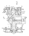
- the four stroke internal combustion engine shown in the drawings comprises a crankcase 1 closed at its underside by a sump 2.
- Three single-cylinder blocks 3A, 3B and 3C are secured to the crank case 1 in alignment with respective openings in the crank walls of the crank case 1 forming three side of a square.
- the cylinders A & C are horizontally opposed and co-axial while the cylinder B has its axis vertical and slightly offset from the common axis of the cylinders A and C.
- Each of the cylinders A, B, C carries a respective cylinder head 6A, 6B, 6C carrying a rocker cover 7A, 7B, 7C.
- Each cylinder block 3 and its head 6 are secured to the crank case 1 by a set of four long studs (one of which is shown at Q in Figure 1) screwed at one end into the crank case and extending through the cylinder head to carry a nut at the other end.
- each cylinder 3 Slidable in each cylinder 3 is a piston 4 carrying conventional pistons rings 5.
- a single-throw crankshaft 8 is journalled in the crank case 1 by being formed with journal portions 9 and 10 which are co-axial and supported in main bearing shells (which may be one-piece shells) in the crank case 1.
- the crankshaft 8 has a single eccentric crank pin 11 connected to the journal portions 9 and 10 by webs which are extended on the opposite side of the crankshaft axis to the crank pin 11 to form counterweights 12.
- a flywheel 13 carrying a conventional starter ring 14 is secured to the crankshaft journal 9 by bolts 15.
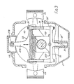
- a drive block 16 which, in radial section and elevation as shown in Fig.3 is of square outline and is split diagonally into two halves secured together by set screws 17 (Fig.4) and carries bearing shells 18.
- Each peripheral face of the drive block 16 forms (or carries) a flat race of a linear roller bearing 20, the other race of the bearing being formed (or carried) by the base portion of a T-shaped connecting arm 21 of a respective connecting link 22 or 23 which straddles the block and defines a rectangular slot or window 24 to receive the drive block 16.
- the connecting link 22 comprises two connecting arms 21A and 21C terminating at their free ends in 'little ends' 26 secured to the respective pistons 4 by conventional gudgeon pins.
- the arms 21A and 21C are spaced by hollow spacers 28 through which extend tie bolts 29 carrying nuts 29 ⁇ to secure the connecting arms 21 and spacers 28 together to form the connecting link 22.
- the connecting link 23 (Fig.3) includes two spacers 28 and tie bolts 29 with their nuts 29 ⁇ . All of the spacers 28 are preferably of the form shown in Figure 3, being tubular with enlarged ends 28 ⁇ to increase the rigidity of the link and maintain the slot or window 24 rectangular.
- the link 23 is completed by a T-shaped member 30, the upper face of which forms a bearing race for a linear bearing 20D engaging the bottom face of the drive block 16.
- the member 30 is extended by a stem 31 incorporating a balance weight, the mass and centre of gravity of which is chosen to ensure that the centre of gravity of the assembly formed by the connecting link 23, the piston 4B and the gudgeon pin 27B coincides with the axis of crank pin 11.
- the stem 31 is slidably guided in a guide sleeve 31 ⁇ in a bridge portion of the sump 2.
- the stem 31 and guide sleeve 31 ⁇ are preferably located in a dry well in the sump 2 to prevent unnecessary waste of power through oil churning losses.
- each linear bearing 20 comprises a set of rollers 32 located in a ladder-type cage 33.
- a pinion 34 is rotatably mounted on the cage 33, conveniently by being located in a slot and being rotatably mounted on one of the rollers 32, and meshes with racks 35 and 36 secured to the bottom walls of grooves 37 and 38 machined respectively in the peripheral faces of the drive block 16 and the connecting arms 21A, B, C and the member 30.
- the pinion 34 by meshing with both of the racks 35 and 36 always ensures that the cage 33 and the rollers 32 move, relative to the links 22, 23 at half the speed of the movement of the drive block 16 relative to the links and thus ensure that there is no slip between the rollers 32 and the races.
- the racks 35 and 36 may be secured by screws S at each end. They and their grooves 37,38 may be T-shaped in cross section with the rack teeth formed on the 'foot' of the T, the wide base of the rack being engaged in the widened base of the groove.
- crankshaft In operation, rotation of the crankshaft imparts a circular motion of the crankpin 11 around the axis of the crankshaft.
- the vertical component of this motion is transmitted through the drive block 16, to the link 23 and thus to the piston 4B.
- the drive block 16 There is no horizontal constraint between the drive block 16 and the link 23, the drive block 16 being able to move horizontally within the window 25 while still transmitting vertical forces (either upwards or downwards) to the link 23 through the bearings 20B and 20D.
- crank pin 11 the horizontal component of motion of the crank pin 11 is transmitted through the drive block 16 and bearings 20A and 20C while the latter bearings permit the drive block to reciprocate in the vertical direction relative to the link 22 without substantial resistance.
- the centre of gravity of the vertically reciprocating mass is made to coincide with the axis of the crank 11.
- the centre of gravity of the horizontally reciprocating masses coincides with the axis of the crank pin.
- the total horizontally reciprocating mass is equal to the total vertically reciprocating mass so that the combined effect of the reciprocating masses is equivalent to a mass concentrated on the axis of the crank pin 11 and thus rotating around the crankshaft axis.
- the effects of this rotating mass can be readily balanced by appropriate choice of the balance weights 12 ( Figure 2).
- the axis of the vertical cylinder B is slightly offset in the direction along the crankshaft axis from the common axis of the cylinders A & C by about half the axial width of the drive block and thus less than the radius of the cylinder bores, in this case being about two thirds of the cylinder bore radius.
- This offset can, if necessary, be avoided by slightly canting the connecting arms 21.
- the construction described above presents several advantages.
- the axial length of the engine is greatly reduced, the engine in effect a radial engine.
- Internal friction within the engine is also reduced since the roller bearings 20 avoid the transmission of side thrusts onto the pistons.
- the main bearing area is reduced by avoiding the loads imposed on a conventional crankshaft by the reciprocating pistons and connecting rods.
- Each cylinder can be formed in a separate single block with a separate single cylinder head, thereby simplifying the tooling up and production processes. Since the crankshaft is a single throw crankshaft, its production is particularly simple and it does not require split main bearing shells.
- each cylinder head 6 has an inlet passage 41 controlled by a pair of inlet valves 42 and an exhaust passage 43 controlled by a pair of exhaust valves 44.
- the inlet and exhaust valves are operated by rocker arms 45, 46 which in turn are controlled by three camshafts 47,48,49 through push rods P and cam followers 50.
- the crankshaft 8 carries a timing gear 51 which meshes with a larger timing gear 52 on the camshaft 49 and, through the latter drives a sprocket wheel 53 engaged with a timing chain 54 driving the other camshafts 47 and 48 which carry further sprocket wheels 55 engaged with the chain 54.
- the camshaft 47 carries a further gear 57 meshing with a gear 58 driving a gear-type oil pump 59 to supply pressure lubrication to the main bearings and thus to lubrication passages 60 within the crankshaft leadings to the crankpin journal, the drive block and linear bearings 20.
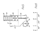
- Figure 6 shows the firing instants of the three cylinders during two revolutions of the crankshaft (720°). As would be expected, the firing intervals are not entirely equal. However, two of these three firing intervals are equal at 270° while the third (A-C) is 180°. Such firing intervals are accordingly sufficiently uniform to be acceptable for most purposes.
- crankshafts with more than one throw, such engines having a set of three cylinders A, B, C for each crankshaft throw.
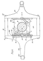
- the connecting link assembly 123 is guided at its upper end by the piston 104B as before.
- the connecting link assembly 123 carries flat elongated guide pads 71, for example of a bearing bronze, which makes sliding contact with elongated linear guides 72 secured to the engine casing for example by means of countersunk screws 73.
- the guide 72 may be of hardened steel.
- the lower element 130 of the connecting link assembly 123 carries the counterweight 74 and also includes two guide horns 75 to provide support area for lowermost extended portions of the guide pads 71 in order to minimise skewing of the connecting link assembly 123.
- the guide blocks 116 may present plain-bearing surfaces, for example of bronze, to the flat faces of the connecting link 121B and the lower member 130, for example of steel.
Landscapes
- Engineering & Computer Science (AREA)
- General Engineering & Computer Science (AREA)
- Mechanical Engineering (AREA)
- Chemical & Material Sciences (AREA)
- Combustion & Propulsion (AREA)
- Shafts, Cranks, Connecting Bars, And Related Bearings (AREA)
- Transmission Devices (AREA)
- Lubrication Of Internal Combustion Engines (AREA)
- Valve Device For Special Equipments (AREA)
Applications Claiming Priority (2)
| Application Number | Priority Date | Filing Date | Title |
|---|---|---|---|
| GB868608237A GB8608237D0 (en) | 1986-04-04 | 1986-04-04 | Reciprocatory positive displacement machines |
| GB8608237 | 1986-04-04 |
Publications (2)
| Publication Number | Publication Date |
|---|---|
| EP0241243A2 true EP0241243A2 (de) | 1987-10-14 |
| EP0241243A3 EP0241243A3 (de) | 1988-01-07 |
Family
ID=10595666
Family Applications (1)
| Application Number | Title | Priority Date | Filing Date |
|---|---|---|---|
| EP87302948A Withdrawn EP0241243A3 (de) | 1986-04-04 | 1987-04-03 | Hubkolbenbrennkraftmaschine |
Country Status (17)
| Country | Link |
|---|---|
| US (1) | US4794887A (de) |
| EP (1) | EP0241243A3 (de) |
| JP (1) | JPH0751901B2 (de) |
| KR (1) | KR910004386B1 (de) |
| CN (1) | CN1013395B (de) |
| AU (1) | AU590696B2 (de) |
| BR (1) | BR8701527A (de) |
| DD (1) | DD256894A5 (de) |
| GB (1) | GB8608237D0 (de) |
| HU (1) | HUT49191A (de) |
| IL (1) | IL82086A0 (de) |
| IN (1) | IN169310B (de) |
| MY (1) | MY101293A (de) |
| NZ (1) | NZ219836A (de) |
| PL (1) | PL264983A1 (de) |
| YU (1) | YU56687A (de) |
| ZA (1) | ZA872394B (de) |
Cited By (12)
| Publication number | Priority date | Publication date | Assignee | Title |
|---|---|---|---|---|
| WO1990006426A1 (en) * | 1988-11-29 | 1990-06-14 | Collins Motor Corporation Limited | Positive displacement fluid machines |
| WO1990014501A1 (en) * | 1989-05-22 | 1990-11-29 | Collins Motor Corporation Limited | Multi-cylinder positive displacement machines |
| WO1993025807A1 (fr) * | 1992-06-09 | 1993-12-23 | Sergei Iosifovich Zalesky | Moteur a combustion interne |
| US5327863A (en) * | 1990-02-21 | 1994-07-12 | Collins Motor Corporation Ltd | Interconnecting rotary and reciprocating motion |
| US5493952A (en) * | 1991-08-20 | 1996-02-27 | Collins Motor Corporation Ltd. | Interconnecting rotary and reciprocating motion |
| WO2000060216A1 (en) * | 1999-04-01 | 2000-10-12 | Peter Robert Raffaele | Reciprocating fluid machines |
| WO2003093701A1 (en) * | 2002-04-30 | 2003-11-13 | Cmc Power Systems Limited | A connection assembly for converting between reciprocal and rotary motion |
| US7210397B2 (en) | 2001-04-27 | 2007-05-01 | Peter Robert Raffaele | Scotch yoke engine |
| WO2009044260A1 (en) * | 2007-10-02 | 2009-04-09 | Gianluigi Benetti | Device for reciprocating machines and related reciprocating machine |
| WO2012022980A1 (en) * | 2010-08-18 | 2012-02-23 | Delixia Limited | Linear-rotational motion converter |
| US8371210B2 (en) | 1998-03-10 | 2013-02-12 | Peter Robert Raffaele | Reciprocating fluid machines |
| WO2021081586A1 (en) * | 2019-10-29 | 2021-05-06 | ASF Technologies (Australia) Pty Ltd | Internal combustion engine having crankshaft guide |
Families Citing this family (17)
| Publication number | Priority date | Publication date | Assignee | Title |
|---|---|---|---|---|
| DE8913971U1 (de) * | 1989-11-27 | 1991-03-28 | Ficht GmbH, 8011 Kirchseeon | Kurbelschleifenrahmen für einen Kurbelschleifentrieb einer Brennkraftmaschine |
| US5203295A (en) * | 1992-08-27 | 1993-04-20 | Spiralex Corp. | Internal combustion engine |
| DE4242101A1 (de) * | 1992-12-14 | 1997-09-18 | Fickelscher Kurt G Dipl Ing | Kolbenmaschine mit Wälzschlittengetriebe |
| DE4314044A1 (de) * | 1993-04-29 | 1994-11-03 | Porsche Ag | Brennkraftmaschine mit zwei Zylinderreihen |
| US5540194A (en) * | 1994-07-28 | 1996-07-30 | Adams; Joseph S. | Reciprocating system |
| DE19504890A1 (de) * | 1995-02-14 | 1996-08-22 | Bayerische Motoren Werke Ag | Hubkolbenmaschine mit in Kurbelwellenrichtung in einem Maschinengehäuse benachbarten Zylindern |
| US5907981A (en) * | 1997-04-14 | 1999-06-01 | Bell; John | Crank apparatus for a crankshaft of an internal combustion engine |
| DE19913889B4 (de) * | 1999-03-26 | 2010-01-21 | Reinhold Ficht | Hubkolbenmaschine |
| US7395790B2 (en) | 2004-11-18 | 2008-07-08 | S&S Cycle, Inc. | Reed valve breather for evolution engine |
| US20120286521A1 (en) * | 2009-11-24 | 2012-11-15 | Georgia Tech Research Corporation | Compact, high-efficiency integrated resonant power systems |
| US20130039789A1 (en) * | 2009-12-17 | 2013-02-14 | Óscar Donado-Muñoz | Vacuum, pressure or liquid pump |
| ITMI20110370A1 (it) * | 2011-03-10 | 2012-09-11 | Giorgio Amedeo Morandi | "motore a combustione interna perfezionato" |
| CN102777483A (zh) * | 2012-07-19 | 2012-11-14 | 中国兵器工业集团第七0研究所 | 一种曲轴止推结构 |
| DE102013106755A1 (de) * | 2013-06-27 | 2014-12-31 | Bertwin R. Geist | Gleitstein für eine Kurbelschlaufen-Hubkolbenmaschine |
| CN110185539B (zh) * | 2019-07-01 | 2024-03-01 | 西北农林科技大学 | 一种双缸内燃机 |
| US12253111B2 (en) * | 2019-10-29 | 2025-03-18 | ASF Technologies (Australia) Pty Ltd | Internal combustion engine having targeted engine lubrication |
| WO2024047271A1 (en) * | 2022-08-31 | 2024-03-07 | Wärtsilä Finland Oy | Multi-piston engine, marine vessel, power plant, method in connection with multi-piston engine and intermediate wheel |
Family Cites Families (25)
| Publication number | Priority date | Publication date | Assignee | Title |
|---|---|---|---|---|
| FR382697A (fr) * | 1907-10-09 | 1908-02-13 | Otto Malms | Moteur à explosion à deux temps à deux ou plusieurs cylindres |
| US1042975A (en) * | 1910-05-10 | 1912-10-29 | William Musser | Internal-combustion engine. |
| FR442867A (fr) * | 1912-04-23 | 1912-09-11 | Georges Roy Harvey | Moteur à combustion interne |
| GB191306029A (en) * | 1913-03-11 | 1913-12-04 | Thomas French And Son Ltd | Improvements in Attache Cases and like Hand Bags. |
| GB170676A (en) * | 1920-07-27 | 1921-10-27 | George Mitchell | Improvements in or relating to internal combustion engines |
| US1878767A (en) * | 1929-11-08 | 1932-09-20 | Richard William Faughnan | Internal combustion engine |
| GB414986A (en) * | 1934-02-24 | 1934-08-16 | William Somerville Renwick | Two-stroke cycle internal-combustion engines |
| US2147666A (en) * | 1937-05-28 | 1939-02-21 | Chauncey M Park | Generation of power |
| US2312057A (en) * | 1941-10-27 | 1943-02-23 | Calvin C Williams | Mechanical movement |
| US2826894A (en) * | 1955-01-31 | 1958-03-18 | August Pablo | Two-stroke cycle internal combustion engine |
| GB827445A (en) * | 1957-11-20 | 1960-02-03 | Luchard Ets | Improvements in multi-cylinder machines |
| US3608530A (en) * | 1970-03-03 | 1971-09-28 | Edward C Wenzel | Lever-type two-cycle internal combustion engine |
| DE2265116A1 (de) * | 1972-09-30 | 1976-09-23 | Franke Walter | Kompressor |
| US3859966A (en) * | 1973-02-16 | 1975-01-14 | Anton Braun | Linear balanced free piston machines |
| GB1447779A (en) * | 1973-10-03 | 1976-09-02 | Norton Villiers Triumph Ltd | Reciprocating piston machines |
| US4344742A (en) * | 1974-12-30 | 1982-08-17 | Ferris James J | Engine apparatus |
| AU1589676A (en) * | 1976-04-30 | 1977-03-10 | Norman George Wheatley | AN ENGINE WITH Specification RECIPROCATING PISTONS ORBITAL THRUST BEARING AND DRIVE CAM |
| AU534084B2 (en) * | 1978-06-06 | 1984-01-05 | Norman George Wheatley | Opposed piston internal combustion engine |
| FR2452589A1 (fr) * | 1979-03-28 | 1980-10-24 | Tardy Robert | Perfectionnements aux machines a pistons |
| US4395977A (en) * | 1981-01-28 | 1983-08-02 | Pahis Nikolaos S | Reciprocate internal combustion engine |
| US4459945A (en) * | 1981-12-07 | 1984-07-17 | Chatfield Glen F | Cam controlled reciprocating piston device |
| JPS58124845A (ja) * | 1982-01-21 | 1983-07-25 | Mazda Motor Corp | 3気筒エンジンのバランサ装置 |
| US4530316A (en) * | 1982-05-10 | 1985-07-23 | Morrison Motor Company | Rotating cylinder internal combustion engine |
| JPS5950247A (ja) * | 1982-09-17 | 1984-03-23 | Honda Motor Co Ltd | 三気筒内燃機関 |
| US4641611A (en) * | 1984-07-06 | 1987-02-10 | West Virginia University | Oscillatory motion apparatus |
-
1986
- 1986-04-04 GB GB868608237A patent/GB8608237D0/en active Pending
-
1987
- 1987-04-01 IL IL82086A patent/IL82086A0/xx unknown
- 1987-04-01 YU YU00566/87A patent/YU56687A/xx unknown
- 1987-04-01 NZ NZ219836A patent/NZ219836A/xx unknown
- 1987-04-02 DD DD87301451A patent/DD256894A5/de unknown
- 1987-04-02 ZA ZA872394A patent/ZA872394B/xx unknown
- 1987-04-03 AU AU71082/87A patent/AU590696B2/en not_active Ceased
- 1987-04-03 CN CN87102539A patent/CN1013395B/zh not_active Expired
- 1987-04-03 MY MYPI87000436A patent/MY101293A/en unknown
- 1987-04-03 JP JP62081342A patent/JPH0751901B2/ja not_active Expired - Lifetime
- 1987-04-03 PL PL1987264983A patent/PL264983A1/xx unknown
- 1987-04-03 KR KR1019870003179A patent/KR910004386B1/ko not_active Expired
- 1987-04-03 BR BR8701527A patent/BR8701527A/pt unknown
- 1987-04-03 HU HU871449A patent/HUT49191A/hu unknown
- 1987-04-03 EP EP87302948A patent/EP0241243A3/de not_active Withdrawn
- 1987-04-06 IN IN255/MAS/87A patent/IN169310B/en unknown
-
1988
- 1988-03-15 US US07/170,631 patent/US4794887A/en not_active Expired - Fee Related
Cited By (15)
| Publication number | Priority date | Publication date | Assignee | Title |
|---|---|---|---|---|
| WO1990006426A1 (en) * | 1988-11-29 | 1990-06-14 | Collins Motor Corporation Limited | Positive displacement fluid machines |
| WO1990014501A1 (en) * | 1989-05-22 | 1990-11-29 | Collins Motor Corporation Limited | Multi-cylinder positive displacement machines |
| US5327863A (en) * | 1990-02-21 | 1994-07-12 | Collins Motor Corporation Ltd | Interconnecting rotary and reciprocating motion |
| US5493952A (en) * | 1991-08-20 | 1996-02-27 | Collins Motor Corporation Ltd. | Interconnecting rotary and reciprocating motion |
| RU2101511C1 (ru) * | 1991-08-20 | 1998-01-10 | Коллинз Мотор Корпорейшн Лимитед | Устройство для преобразования возвратно-поступательного движения во вращательное и наоборот и устройство с возвратно-поступательно движущимися частями |
| WO1993025807A1 (fr) * | 1992-06-09 | 1993-12-23 | Sergei Iosifovich Zalesky | Moteur a combustion interne |
| US8371210B2 (en) | 1998-03-10 | 2013-02-12 | Peter Robert Raffaele | Reciprocating fluid machines |
| WO2000060216A1 (en) * | 1999-04-01 | 2000-10-12 | Peter Robert Raffaele | Reciprocating fluid machines |
| US7210397B2 (en) | 2001-04-27 | 2007-05-01 | Peter Robert Raffaele | Scotch yoke engine |
| CN100575745C (zh) * | 2002-04-30 | 2009-12-30 | Cmc动力系统有限公司 | 用于在往复运动和旋转运动之间转换的连接组件 |
| WO2003093701A1 (en) * | 2002-04-30 | 2003-11-13 | Cmc Power Systems Limited | A connection assembly for converting between reciprocal and rotary motion |
| WO2009044260A1 (en) * | 2007-10-02 | 2009-04-09 | Gianluigi Benetti | Device for reciprocating machines and related reciprocating machine |
| WO2012022980A1 (en) * | 2010-08-18 | 2012-02-23 | Delixia Limited | Linear-rotational motion converter |
| WO2021081586A1 (en) * | 2019-10-29 | 2021-05-06 | ASF Technologies (Australia) Pty Ltd | Internal combustion engine having crankshaft guide |
| US12140074B2 (en) | 2019-10-29 | 2024-11-12 | ASF Technologies (Australia) Pty Ltd | Internal combustion engine having crankshaft guide |
Also Published As
| Publication number | Publication date |
|---|---|
| HUT49191A (en) | 1989-08-28 |
| KR870010276A (ko) | 1987-11-30 |
| ZA872394B (en) | 1988-02-24 |
| CN87102539A (zh) | 1987-11-04 |
| NZ219836A (en) | 1989-08-29 |
| DD256894A5 (de) | 1988-05-25 |
| IL82086A0 (en) | 1987-10-30 |
| AU7108287A (en) | 1987-10-22 |
| MY101293A (en) | 1991-09-05 |
| PL264983A1 (en) | 1988-05-26 |
| US4794887A (en) | 1989-01-03 |
| CN1013395B (zh) | 1991-07-31 |
| GB8608237D0 (en) | 1986-05-08 |
| JPS62294722A (ja) | 1987-12-22 |
| JPH0751901B2 (ja) | 1995-06-05 |
| EP0241243A3 (de) | 1988-01-07 |
| KR910004386B1 (ko) | 1991-06-26 |
| YU56687A (en) | 1990-12-31 |
| BR8701527A (pt) | 1988-01-19 |
| IN169310B (de) | 1991-09-28 |
| AU590696B2 (en) | 1989-11-09 |
Similar Documents
| Publication | Publication Date | Title |
|---|---|---|
| US4794887A (en) | Reciprocatory internal combustion engines | |
| RU2154178C2 (ru) | Поршневой двигатель внутреннего сгорания, имеющий кривошипный механизм со сдвоенным круглым скользящим блоком | |
| US8474435B2 (en) | Opposed piston, compression ignition engine with single-side mounted crankshafts and crossheads | |
| RU155542U1 (ru) | Двигатель внутреннего сгорания | |
| US8281763B2 (en) | Internal combustion engine | |
| US4884536A (en) | Interconnecting rotary and reciprocatory motion | |
| RU2101511C1 (ru) | Устройство для преобразования возвратно-поступательного движения во вращательное и наоборот и устройство с возвратно-поступательно движущимися частями | |
| US6082314A (en) | Multiple circular slider crank reciprocating piston internal combustion engine | |
| US4694785A (en) | Piston apparatus | |
| JPS62159826A (ja) | ピストン式内燃機関の振動を減らすためのつりあい機構 | |
| US8485161B2 (en) | Opposed piston, compression ignition engine with single-side mounted crankshafts and crossheads | |
| JPH0419454A (ja) | プラネタリピボットピンを有するクランクドライブ | |
| US4651689A (en) | Internal combustion engine with first order mass balancing | |
| RU2556771C2 (ru) | Система масс противоположного вращения для использования с рядным четырехцилиндровым двигателем внутреннего сгорания для уравновешивания вибраций, образуемых двигателем, и рядный четырехцилиндровый двигатель, содержащий такую систему | |
| US6435145B1 (en) | Internal combustion engine with drive shaft propelled by sliding motion | |
| US2013163A (en) | Engine | |
| JP4383574B2 (ja) | 4サイクルv型8気筒エンジン用バランス装置 | |
| WO1989003477A1 (en) | Positive displacement fluid machines | |
| RU2011061C1 (ru) | Механизм уравновешивания поршневой машины | |
| RU2018039C1 (ru) | Устройство для уравновешивания поршневой машины | |
| DE68901811T2 (de) | Brennkraftmaschine. | |
| RU2793028C1 (ru) | Двигатель внутреннего сгорания двустороннего действия | |
| KR890014927A (ko) | 내연기관용 왕복동 실린더-피스턴조립체 | |
| GB2525213A (en) | OSP with rectilinear drive mechanism | |
| EP0503842A1 (de) | Brennkraftmaschine |
Legal Events
| Date | Code | Title | Description |
|---|---|---|---|
| PUAI | Public reference made under article 153(3) epc to a published international application that has entered the european phase |
Free format text: ORIGINAL CODE: 0009012 |
|
| AK | Designated contracting states |
Kind code of ref document: A2 Designated state(s): AT DE ES FR GB IT SE |
|
| PUAL | Search report despatched |
Free format text: ORIGINAL CODE: 0009013 |
|
| AK | Designated contracting states |
Kind code of ref document: A3 Designated state(s): AT DE ES FR GB IT SE |
|
| 17P | Request for examination filed |
Effective date: 19880705 |
|
| 17Q | First examination report despatched |
Effective date: 19890918 |
|
| STAA | Information on the status of an ep patent application or granted ep patent |
Free format text: STATUS: THE APPLICATION IS DEEMED TO BE WITHDRAWN |
|
| 18D | Application deemed to be withdrawn |
Effective date: 19910702 |
|
| RIN1 | Information on inventor provided before grant (corrected) |
Inventor name: VALENTINE,RONALD EDWIN |