EP0240477A2 - Strassenfertiger für bituminöse Strassendecken mit hebbaren, einstellbaren Förderschnecken - Google Patents
Strassenfertiger für bituminöse Strassendecken mit hebbaren, einstellbaren Förderschnecken Download PDFInfo
- Publication number
- EP0240477A2 EP0240477A2 EP87850105A EP87850105A EP0240477A2 EP 0240477 A2 EP0240477 A2 EP 0240477A2 EP 87850105 A EP87850105 A EP 87850105A EP 87850105 A EP87850105 A EP 87850105A EP 0240477 A2 EP0240477 A2 EP 0240477A2
- Authority
- EP
- European Patent Office
- Prior art keywords
- augers
- drive box
- paver
- auger
- tractor
- Prior art date
- Legal status (The legal status is an assumption and is not a legal conclusion. Google has not performed a legal analysis and makes no representation as to the accuracy of the status listed.)
- Granted
Links
- 239000010426 asphalt Substances 0.000 title claims abstract description 30
- 230000007246 mechanism Effects 0.000 title abstract description 32
- 239000000463 material Substances 0.000 claims description 16
- 239000011435 rock Substances 0.000 claims 3
- 230000000694 effects Effects 0.000 claims 1
- 230000008901 benefit Effects 0.000 description 9
- 210000003414 extremity Anatomy 0.000 description 5
- 238000012423 maintenance Methods 0.000 description 4
- 238000010276 construction Methods 0.000 description 3
- 238000006073 displacement reaction Methods 0.000 description 3
- 230000002706 hydrostatic effect Effects 0.000 description 3
- 238000000034 method Methods 0.000 description 3
- 230000006641 stabilisation Effects 0.000 description 2
- 230000009471 action Effects 0.000 description 1
- 230000000712 assembly Effects 0.000 description 1
- 238000000429 assembly Methods 0.000 description 1
- 230000009286 beneficial effect Effects 0.000 description 1
- 230000000903 blocking effect Effects 0.000 description 1
- 230000015556 catabolic process Effects 0.000 description 1
- 238000006731 degradation reaction Methods 0.000 description 1
- 238000009434 installation Methods 0.000 description 1
- 210000003141 lower extremity Anatomy 0.000 description 1
- 230000000737 periodic effect Effects 0.000 description 1
- 230000008569 process Effects 0.000 description 1
- 230000009467 reduction Effects 0.000 description 1
- 230000008439 repair process Effects 0.000 description 1
- 150000003839 salts Chemical class 0.000 description 1
- 238000011105 stabilization Methods 0.000 description 1
- 238000003466 welding Methods 0.000 description 1
Images


Classifications
-
- E—FIXED CONSTRUCTIONS
- E01—CONSTRUCTION OF ROADS, RAILWAYS, OR BRIDGES
- E01C—CONSTRUCTION OF, OR SURFACES FOR, ROADS, SPORTS GROUNDS, OR THE LIKE; MACHINES OR AUXILIARY TOOLS FOR CONSTRUCTION OR REPAIR
- E01C19/00—Machines, tools or auxiliary devices for preparing or distributing paving materials, for working the placed materials, or for forming, consolidating, or finishing the paving
- E01C19/48—Machines, tools or auxiliary devices for preparing or distributing paving materials, for working the placed materials, or for forming, consolidating, or finishing the paving for laying-down the materials and consolidating them, or finishing the surface, e.g. slip forms therefor, forming kerbs or gutters in a continuous operation in situ
- E01C19/4866—Machines, tools or auxiliary devices for preparing or distributing paving materials, for working the placed materials, or for forming, consolidating, or finishing the paving for laying-down the materials and consolidating them, or finishing the surface, e.g. slip forms therefor, forming kerbs or gutters in a continuous operation in situ with solely non-vibratory or non-percussive pressing or smoothing means for consolidating or finishing
- E01C19/4873—Apparatus designed for railless operation
-
- E—FIXED CONSTRUCTIONS
- E01—CONSTRUCTION OF ROADS, RAILWAYS, OR BRIDGES
- E01C—CONSTRUCTION OF, OR SURFACES FOR, ROADS, SPORTS GROUNDS, OR THE LIKE; MACHINES OR AUXILIARY TOOLS FOR CONSTRUCTION OR REPAIR
- E01C19/00—Machines, tools or auxiliary devices for preparing or distributing paving materials, for working the placed materials, or for forming, consolidating, or finishing the paving
- E01C19/22—Machines, tools or auxiliary devices for preparing or distributing paving materials, for working the placed materials, or for forming, consolidating, or finishing the paving for consolidating or finishing laid-down unset materials
- E01C19/42—Machines for imparting a smooth finish to freshly-laid paving courses other than by rolling, tamping or vibrating
Definitions
- the invention is directed generally to improvements in asphalt pavers of the floating screed type.
- the invention is directed to improvements in the mounting and positioning of the auger mechanisms typically employed with such pavers.
- floating screed type paving machines In the laying of asphalt pavement roadways, it is common practice to utilize floating screed type paving machines. These machines typically include a tractor-like vehicle having an engine for propulsion and for material distributing functions. A material receiving hopper is provided at the front of the paver, arranged to receive hot asphalt materials from a truck, as the paving machine advances along the roadbed. Means, such as slat conveyors, are provided to convey the asphalt material rearward from the hopper and to deposit the material on the roadway, in front of the floating screed.
- a distributing auger mechanism comprising left and right side augers positioned in the region in which the asphalt is deposited from the salt conveyors.
- the raw asphalt material is first deposited by the slat conveyors and then distributed laterally outward by the augers.
- the distributed material then flows under the floating screed, which levels, smooths and compacts the asphalt to provide a continuous, level pavement mat.
- the auger elements are mounted at the back of the paver in a substantially fixed position. While means typically may be provided to enable limited vertical adjustment of the augers, the nature of the known equipment is such that adjustments are rarely if ever be utilized after the initial setting. Historically, height adjustment of the auger mechanism has involved multiple manual adjustments of turnbuckles and bearing mounts, in some instances at locations which may be heavily coated with asphalt. Accordingly, adjustment of the auger height with the paver on the move has been altogether out of the question, and adjustment at other times is sufficiently complex and time consuming as to rule it out for most purposes.
- a novel and improved arrangement is provided for constructing and mounting the auger and auger drive mechanisms for limited vertical liftability and height adjustment relative to the tractor frame, such that the auger can be instantly and effortlessly raised or lowered relative to the paver.
- the auger may be set relatively close to the roadbed for normal paving operations, to achieve optimum function during paving, and yet may be instantly raised to clear roadbed obstructions, for example, such as manhole projections.
- roadbed obstructions for example, such as manhole projections.
- the new liftable auger mechansim includes a drive box, which is mounted centrally, at the back of the paver, and supports the inboard ends of each of the left and right side auger elements. Support for the outboard ends of the augers is provided by means of a laterally extending cantilever beam, which is carried by the drive box and extends outward over the top of the auger elements. At one or more outboard locations, depending upon the length of the auger elements, support bearings are provided, extending downward from the cantilever beam.
- the entire auger mechanism is supported for limited movement by pivotal attachment of the drive box to the back of the paver frame.
- An hydraulic lift mechanism engages the cantilever beam at relatively widely spaced points, on opposite sides of the drive box, in order to pivot the assembly.
- the pivot axis of the drive box is located forwardly of the auger and generally at the same horizontal level, such that pivoting movement of the drive box is translated into generally vertical movement of the augers.
- the laterally extending cantilever beam is movably supported by the paver frame at spaced outboard locations, to provide for mechanical stability of the entire structure.
- thrust resisting means may be provided respectively on the cantilever beams and paver frame, to assist in resisting the unbalanced sideways thrusting forces developed by the augers during normal paving operations.
- the new auger mechanism is constructed as a substantially unitary module, which can be installed on and removed from the paver substantially as a single unit, greatly facilitating assembly, maintenance and repair operations.
- the reference numeral 10 indicates generally an asphalt paver of the floating screed type.
- the illustrated paver, utilizing large diameter, pneumatically tired drive wheels 19. may be of the general type described in the Davin U.S. Patent No. 3,584,547 and marketed commercially by Blaw-Knox Construction Equipment of Mattoon, Illinois.
- a common alternative form of floating screed asphalt paver is also shown in the Davin U.S. Patent 3,776,326, which utilize endless tracks rather than pneumatically tired wheels for propulsion.
- the improved auger mechanism of the invention is utilizable to advantage in either form of paver and, indeed, may be useful to advantage in pavers other than floating screed pavers, for example.
- a paver of the type illustrated in Fig. 1 typically is provided with a hopper 11 in its front section, which is arranged to receive hot asphalt material from a dump truck located directly in front of the paver and typically pushed down the roadway by the paver during paving operations.
- An engine 12 provides motive power for the paver.
- conveyor means are provided to move the hot asphalt material from the area of the hopper 11 rearward, to be discharged at the back of the machine, as indicated at 13. Since the area being paved is usually of considerably greater width than the effective width of the material conveyors, and frequently considerably greater than the width of the paver apparatus as a whole, it is conventional to provide auger elements 14 at the back of the paver, carried slightly above the roadway surface 15. These augers are controllably driven in a manner to distribute the hot asphalt laterally outward from the central region in which the material is discharged by the conveyors.
- a floating screed 16 is positioned immediately behind the auger means 14 and is conneted to the paver frame by spaced towing arms 17.
- the towing arms are pivotally connected to the paver frame at tow points 18, which may be adjusted vertically upward and downward in accordance with known principles to control the attitude of the screed 16.
- a drive box 20 is pivotally mounted at the back of the paver 10 and serves to both mount and support the respective left and right side augers 21,22.
- the augers themselves may be of conventional construction, comprising internal shafts, 23,23a on which are mounted a plurality of auger segments 24, which can be arranged in succession to form a more or less continuous helix.
- paddle devices 25,26 are provided at the inboard and outboard extremities of the auger shafts.
- the inboard ends of the auger shafts 23,23a are supported in bearings 27,28 secured to spaced side plates 29,30 of the drive box 20.
- the extremities of the auger shafts 23,23a project into the drive box and have fixed thereto respective drive sprockets 31,32 driven by chains 33,34.
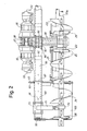
- the chains in turn are driven by hydraulic motors 35,36 mounted at the upper rear portions of the drive box 20, as shown in Figs. 2 and 3, and carrying sprockets 37,38.
- the motors 35,36 may advantageously be fixed displacement hydrostatic motors, driven by variable displacement hydrostatic pumps (not shown) to provide variable speed operation of the augers, usually by means of a control responsive to the height of the pile of asphalt in the region of the augers.
- bearings 40,41 At the lower forward portion of the drive box 20 there are mounted bearings 40,41, bolted or otherwise secured to the respective sidewalls 29, 30 of the drive box. These bearings support drive shafts 42,43 for left and right side slat conveyors (not shown) for moving asphalt from the hopper 10 at the front of the paver back to the area of the auger 14. As illustrated in Fig. 7, the outboard ends of the shafts 42,43 are supported by pillow blocks 44 bolted to a member 45a of the paver frame (see Fig. 3) immediately outboard of side plates 45 forming part of the paver tractor frame. Between the bearings 40,41 and the respective outboard pillow blocks 44, each of the conveyor drive shafts mounts a pair of spaced conveyor drive sprockets 46 arranged to engage chains 47 forming part of the slat conveyor.
- the respective conveyor shafts 42,43 mount drive sprockets 48,49 driven by chains 50,51 from independent hydraulic motors 52,53 mounted at the upper portions of upper forward portions of the drive box 20.
- the conveyor drive motors 52,53 may be controllably driven by variable displacement hydrostatic pumps (not shown), under either automatic or manual control, so as to deliver paving material to the augers an appropriate rate in relation to its utilization in the paving process.
- the drive box 20 is pivotally mounted at the back of the paver by means of a pair of saddle brackets 55,56, which are received over the circular flanges 57 of the inner shaft bearings 40,41 (see Fig. 7).
- the flanges 57 are of circular outline and are received within circular openings in the respective saddle brackets 55,56, so that relative pivotal movement is permitted.
- the saddle brackets are provided with respective forwardly projecting flanges 58 and laterally outwardly projecting flanges 59.
- the latter are secured by bolts 60 to a transverse channel member 61 forming part of the machine frame, while the former, 58, are secured by bolts 62 to another fixed part of the machine frame.
- the arrangement is such that the entire drive box and auger mechanism is supported by the saddle brackets 55,56 for pivotal movement about the common axis of the conveyor drive shafts 42,43.
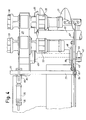
- the auger mechanism of the invention includes a horizontally disposed tubular beam 70, which extends through the walls of the drive box 20 and is secured thereto as by welding.
- the tubular beam extends in cantilever fashion outward over the top of the auger sections 21,22, approximately to the outer ends of the respective auger shafts 23,23a.
- the structural arrangement of the drive box, tubular beam and augers, as can be observed in Fig. 23, is of a self-contained, modular nature, which greatly facilitates mounting and removal of the mechanism from the tractor frame and thus simplifies assembly on maintenance procedures.
- Stabilization of the auger and auger drive module is achieved in part by the attachment of the connecting links 84 to outboard ends of the tubular beam 70.
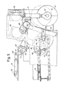
- mechanical stabilisation is provided by means of generally arcuate slots 85, formed in the structural side plates 45 of the paver tractor (see Fig. 5).
- the slots 85 are formed on a radius about the axis of the conveyor shafts 42,43 and serve generally to confine movement of the outboard ends of the tubular beam 70, while accommodating the desired motion thereof as a result of pivotal movement of the drive box.
- the slot 85 Adjacent the open outer end, the slot 85 may be provided with a generally horizontal surface 86 upon which tubular beam 70 may directly rest when the hydraulic actuator 75 is deenergized.
- the augers 21,22 serve to push asphalt laterally outward.
- the momentary individual loading upon the left and right side augers may vary, such that the net side thrust of the augers may vary more or less continuously and may shift from side to side in terms of direction.
- this variable side thrust is partly absorbed by means of abutment collars 87 mounted on the tubular beam 70 at each side and cooperating with the frame side plates 45.
- the abutment collars 87 are somewhat larger in diameter than the width of the guide slots 85, so that any tendency for the tubular cantilever beam to be driven to one side or the other by unbalanced forces from the augers 21,22, causes one or the other of the collars 87 to abut against the frame plate 45. This serves to reduce the side loads placed upon the saddle brackets 55,56, as will be understood.
- a paver In typical operation, a paver must be adaptable to paving of various widths, from the width of the paver itself, as a typical minimum, to a maximum width significantly wider that the paver. For such applications, it has been typical practice to provide width extensions for the screed and auger assemblies, enabling the paving material to be spread laterally to a greater distance and then smoothed and flattened by the wider screed.
- extension of the auger mechanism is accommodated by providing for a telescoping outer section of the tubular beam 70.
- the reference numeral 90 represents a tubular beam extension arranged to slide internally of the main tubular beam 70.
- the beam extension 90 is provided along its length with a plurality of spaced through openings 91, enabling the extension to be secured in a variety of extended positions, by means of a pull pin 93 inserted in a pair of openings in each end of the main tubular beam 70.
- a pair of spaced annular bearing collars 92, near the inboard end of the extension 90, provide for a smooth sliding fit of the respective tubular members 70,90.
- the lateral extension of the tubular beam 70 serves to extend laterally a guard means which is provided in front of the auger elements.
- a guard means which is provided in front of the auger elements.
- additional bearing support is illustrated in Fig. 5, where the bearing support 94, similar to the previously described bearing support 71, is clamped to the beam extension 90 by a clamping block 95 and carries a shaft bearing 96 at its lower end for engagement with an outboard extension of the auger shaft.
- a first guard plate 100 is welded or otherwise secured to the outboard portion of the main beam 70, on each side of the paver, providing a front guard for the outboard section of a minimum length auger.
- the inboard sections of the augers do not require a special guard as they are located directly behind the paver and of course they must be open to the discharge ends of the conveyor means carrying asphalt rearward from the front hopper.
- the inner guard plate 100 extends downward and is bent forwardly and slightly upward at its lower terminal end.
- a second guard plate 101 Nested in front of the plate 100 is a second guard plate 101, which is attached to the outer end extremity of the tubular beam extension 90 and extends inwardly from the end of the beam extension.
- the actuator 75 typically would be actuated to the position shown in Fig. 5, causing the auger sections 21,22 to be generally in their lower limit positions. In this position, the lower extremity of the auger elements would ride a few inches above the prepared road surface, sufficient to avoid damaging contact of the auger with the road surface during normal operations.
- the entire auger mechanism can be easily raised by appropriately energizing the hydraulic actuator 75, pivoting the entire drive box, beam assembly etc. and raising the auger elements themselves in a generally vertical direction.
- the location of the auger mechanism is well behind the rear wheels of the paver, or behind the tracks of the paver, if a track laying version is being utilized.
- a slight upward tilting of the paver in order to move the paver from one job side to another, even a slight upward tilting of the paver, as it begins to ascend an inclined ramp to the trailer body, tends to cause the augers 14 to contact the road surface.
- this has been a cause of considerable problem and damage to the auger mechanism.
- all that is necessary is to energize the hydraulic actuator 75, lifting the augers through a full vertical stroke of five to six inches and clearing the augers out of harms way for loading and unloading.
- the mechanism of the invention is also highly beneficial for relatively higher speed, over the road travel of the paver when moving from one location to another in a non-paving mode.
- high speed movement of the paver can be accompanied by considerably bouncing on the pneumatic rear tires, which are purposely under inflated to provide a broad footprint for paving.
- damage to the auger is always a potential problem with conventional pavers moving in the travel mode.
- a simple control operation by the driver raises the augers out of the way sufficiently for safe travel.
- An additional benefit of the new auger and auger drive mechanism is its essentially modular construction.
- the entire modular unit can be engaged by a forklift truck and brought to the back of the paver (the screed at this time having been dropped from the paver).
- the saddle brackets 55,56 are first attached to the paver frame, by means of the bolts 60,62.
- the connecting links 84 are attached and the outer pillow blocks 44, at the outer ends of the conveyor drive shafts 42,43, are bolted to the machine frame.
- a curved guard plate 110 (Fig. 5) is installed over and around each of the conveyor drive shafts 42,43 to provide guidance and support for the slat conveyor elements 111 as they round the sprockets 46.
- the job also can be performed without a forklift, by properly blocking the auger mechanism at the desired height and then backing the paver into position for assembly.
- the guard panel 100 depending from the tubular beam elements 70 may be provided with openings for the mounting of a temporary support bracket 115 (see schematic representation in Fig. 7).
- a temporary support bracket 115 see schematic representation in Fig. 7.
- the new auger and auger drive mechanism thus not only enables significantly superior performance of the paving equipment in the course of its normal operations, but also enables significant advantages to be realized in assembly/disassembly operations, and substantial economies thereby to be realized in connection with maintenance and servicing of the equipment.
Landscapes
- Engineering & Computer Science (AREA)
- Architecture (AREA)
- Civil Engineering (AREA)
- Structural Engineering (AREA)
- Road Paving Machines (AREA)
Applications Claiming Priority (2)
| Application Number | Priority Date | Filing Date | Title |
|---|---|---|---|
| US848719 | 1986-04-04 | ||
| US06/848,719 US4708519A (en) | 1986-04-04 | 1986-04-04 | Asphalt paving machine with liftable, adjustable auger mechanisms |
Publications (3)
| Publication Number | Publication Date |
|---|---|
| EP0240477A2 true EP0240477A2 (de) | 1987-10-07 |
| EP0240477A3 EP0240477A3 (en) | 1988-07-27 |
| EP0240477B1 EP0240477B1 (de) | 1991-03-20 |
Family
ID=25304088
Family Applications (1)
| Application Number | Title | Priority Date | Filing Date |
|---|---|---|---|
| EP87850105A Expired EP0240477B1 (de) | 1986-04-04 | 1987-03-31 | Strassenfertiger für bituminöse Strassendecken mit hebbaren, einstellbaren Förderschnecken |
Country Status (4)
| Country | Link |
|---|---|
| US (1) | US4708519A (de) |
| EP (1) | EP0240477B1 (de) |
| JP (1) | JPS62276104A (de) |
| DE (1) | DE3768688D1 (de) |
Cited By (3)
| Publication number | Priority date | Publication date | Assignee | Title |
|---|---|---|---|---|
| EP0774542A1 (de) * | 1995-11-16 | 1997-05-21 | Niarb S.A. | Strassendeckenfertiger mit automatischer Regelung der Höhe des Querverteilers relativ zur Glättbohle |
| JP2010138559A (ja) * | 2008-12-09 | 2010-06-24 | Sumitomo (Shi) Construction Machinery Co Ltd | 舗装機械における伸縮可能なリテーニングプレート装置 |
| CN109477318A (zh) * | 2016-06-10 | 2019-03-15 | 丹帕克有限公司 | 筑路机械和用于运行自行驶的筑路机械的方法 |
Families Citing this family (28)
| Publication number | Priority date | Publication date | Assignee | Title |
|---|---|---|---|---|
| US4925340A (en) * | 1989-05-12 | 1990-05-15 | Sundstrand-Sauer | Screed slope controller for a paver |
| JPH0358310U (de) * | 1989-10-09 | 1991-06-06 | ||
| US5002426A (en) * | 1989-12-15 | 1991-03-26 | Blaw-Knox Construction Equipment Corporation | Paddle mixer for asphalt pavers |
| US5073063A (en) * | 1990-08-20 | 1991-12-17 | White Consolidated Industries, Inc. | Windrow paving machine and method of paving |
| US5232305A (en) * | 1991-05-15 | 1993-08-03 | Caterpillar Paving Products Inc. | Paving material distribution system |
| US5348418A (en) * | 1992-05-05 | 1994-09-20 | Astec Industries, Inc. | Asphalt finishing screed having rotary compactor |
| US5279501A (en) * | 1992-06-15 | 1994-01-18 | Caterpillar Paving Products Inc. | Screw conveyor |
| US5615973A (en) * | 1994-09-29 | 1997-04-01 | Astec Industries, Inc. | Paving machine with gravity feed hopper and auger mechanism |
| US5533828A (en) * | 1994-09-29 | 1996-07-09 | Astec Industries, Inc. | Method and apparatus for discharging paving materials on top of distributing auger |
| US5531542A (en) * | 1994-11-14 | 1996-07-02 | Ingersoll-Rand Company | Dual auger/conveyor drive for a paver |
| DE19707683C2 (de) * | 1997-02-26 | 2003-04-30 | Metso Dynapac Gmbh | Straßenfertiger |
| US6203244B1 (en) * | 1998-01-15 | 2001-03-20 | Van-Boh Systems, Inc. | Screeding apparatus |
| US6074298A (en) * | 1998-06-17 | 2000-06-13 | Crary Company | Extended height combine hopper leveling auger |
| DE10023023C1 (de) * | 2000-05-11 | 2001-10-18 | Abg Allg Baumaschinen Gmbh | Straßenfertiger |
| US6802667B2 (en) * | 2000-07-17 | 2004-10-12 | Blaw-Knox Construction Equipment Corporation | Material anti-segregation curtain for a paver |
| US6821052B2 (en) * | 2001-10-09 | 2004-11-23 | William Harrison Zurn | Modular, robotic road repair machine |
| US6715957B2 (en) * | 2001-10-17 | 2004-04-06 | Power Curbers, Inc. | Paving apparatus with retractable pavement forming assembly |
| US20060216113A1 (en) * | 2005-03-24 | 2006-09-28 | Richard Silbernagel | Road construction apparatus with pivotally connected trimmer |
| US8162565B2 (en) * | 2008-04-01 | 2012-04-24 | Volvo Construction Equipment Ab | Break-away material retainer for paving vehicles |
| US8562248B2 (en) * | 2009-09-18 | 2013-10-22 | Patch Management, Inc. | Method and apparatus for repairing potholes and the like |
| US8931975B2 (en) * | 2011-06-06 | 2015-01-13 | Hot Mix Mobile, Llc | Mobile asphalt concrete production machine |
| DE202012003753U1 (de) * | 2012-04-13 | 2013-07-17 | Joseph Vögele AG | Querverteilanordnung für einen Straßenfertiger |
| DE202012003792U1 (de) * | 2012-04-13 | 2013-07-17 | Joseph Vögele AG | Straßenfertiger mit variabler Schneckenaufhängung |
| CN102979030A (zh) * | 2012-12-12 | 2013-03-20 | 江阴同创体育机械有限公司 | 摊铺机 |
| US9938673B2 (en) * | 2016-02-18 | 2018-04-10 | Caterpillar Paving Products Inc. | System and method for controlling auger of paving machine |
| WO2018208753A1 (en) * | 2017-05-09 | 2018-11-15 | Somero Enterprises, Inc. | Concrete screeding system with rotatable screed head |
| PL3757290T3 (pl) * | 2019-06-26 | 2021-11-08 | Joseph Vögele AG | Układ rozdzielacza poprzecznego do wykańczarki |
| US12000096B2 (en) * | 2021-02-02 | 2024-06-04 | Caterpillar Paving Products Inc. | Auger segment and systems, assemblies, and methods thereof |
Family Cites Families (15)
| Publication number | Priority date | Publication date | Assignee | Title |
|---|---|---|---|---|
| US1993656A (en) * | 1932-04-09 | 1935-03-05 | Jacger Machine Company | Method and apparatus for building roads |
| US2346379A (en) * | 1941-07-23 | 1944-04-11 | Jackson Corwill | Method of and apparatus for placing pavement slabs and the like |
| US2583108A (en) * | 1945-06-18 | 1952-01-22 | Standard Steel Corp | Concrete spreader |
| US2589256A (en) * | 1948-07-01 | 1952-03-18 | Jaeger Machine Co | Road-paving machine |
| US3015259A (en) * | 1960-01-26 | 1962-01-02 | Jaeger Machine Co | Paving material spreader |
| US3130654A (en) * | 1961-08-31 | 1964-04-28 | Jaeger Machine Co | Material distributing and leveling machine |
| US3221618A (en) * | 1962-03-16 | 1965-12-07 | Rex Chainbelt Inc | Pavement laying and finishing apparatus |
| US3584547A (en) * | 1968-12-27 | 1971-06-15 | Blaw Knox Co | Bogie suspension system |
| DE1965141B2 (de) * | 1969-12-27 | 1978-01-19 | Abg-Werke Gmbh, 3250 Hameln | Strassenfertiger |
| US3776326A (en) * | 1969-12-31 | 1973-12-04 | Blaw Knox Const Equipment | Paving machine |
| US3874807A (en) * | 1973-04-16 | 1975-04-01 | R Otis Puckett | Self-propelled asphalt spreader |
| US3907451A (en) * | 1974-01-28 | 1975-09-23 | Lay Mor Manufacturing Company | Extensible screed and auger assembly for a road paving machine |
| US3901616A (en) * | 1974-07-22 | 1975-08-26 | Kenneth J Greening | Self-propelled paver |
| JPS605051U (ja) * | 1983-06-23 | 1985-01-14 | 日本電気株式会社 | 輻射冷却形多段コレクタ |
| JPS6058323A (ja) * | 1983-09-05 | 1985-04-04 | 川崎製鉄株式会社 | 包装紙に折目をつける方法 |
-
1986
- 1986-04-04 US US06/848,719 patent/US4708519A/en not_active Expired - Lifetime
-
1987
- 1987-03-31 DE DE8787850105T patent/DE3768688D1/de not_active Expired - Lifetime
- 1987-03-31 EP EP87850105A patent/EP0240477B1/de not_active Expired
- 1987-04-04 JP JP62082236A patent/JPS62276104A/ja active Pending
Cited By (3)
| Publication number | Priority date | Publication date | Assignee | Title |
|---|---|---|---|---|
| EP0774542A1 (de) * | 1995-11-16 | 1997-05-21 | Niarb S.A. | Strassendeckenfertiger mit automatischer Regelung der Höhe des Querverteilers relativ zur Glättbohle |
| JP2010138559A (ja) * | 2008-12-09 | 2010-06-24 | Sumitomo (Shi) Construction Machinery Co Ltd | 舗装機械における伸縮可能なリテーニングプレート装置 |
| CN109477318A (zh) * | 2016-06-10 | 2019-03-15 | 丹帕克有限公司 | 筑路机械和用于运行自行驶的筑路机械的方法 |
Also Published As
| Publication number | Publication date |
|---|---|
| DE3768688D1 (de) | 1991-04-25 |
| US4708519A (en) | 1987-11-24 |
| EP0240477B1 (de) | 1991-03-20 |
| EP0240477A3 (en) | 1988-07-27 |
| JPS62276104A (ja) | 1987-12-01 |
Similar Documents
| Publication | Publication Date | Title |
|---|---|---|
| EP0240477B1 (de) | Strassenfertiger für bituminöse Strassendecken mit hebbaren, einstellbaren Förderschnecken | |
| US5344254A (en) | Pivoting screed edger | |
| EP0957204B1 (de) | Strassenfertiger und Beschicker hierfür | |
| US5100277A (en) | Method of and apparatus for transferring materials | |
| US3130654A (en) | Material distributing and leveling machine | |
| EP0539570B1 (de) | Strassenfertiger mit fahrbahnmaterialverteilungssystem | |
| US7244077B2 (en) | Method for controlling material flow in a paving machine | |
| AU2015369821B2 (en) | Material transfer vehicle having an expandable truck-receiving hopper | |
| US2848930A (en) | Pavement widening machine | |
| JPS596964B2 (ja) | 護岸舗装用装具 | |
| CA2472266C (en) | Multi-use paving tractor with tool attachments | |
| US3015261A (en) | Trench filling and shoulder spreading machine | |
| US4790715A (en) | Dump truck accessory | |
| GB2051190A (en) | Device for laying road material | |
| US3216337A (en) | Spreader attachment | |
| US5197848A (en) | Methods of and apparatus for transferring materials | |
| WO2001025544A1 (en) | Detachable dowel bar inserter kit for portable slip form paver | |
| US4815542A (en) | Ground leveling attachment for box-scraper | |
| US5873186A (en) | Excavating machine with cleaning device | |
| US5114267A (en) | Integrated paver with windrow pick-up capability | |
| US20030143024A1 (en) | Method and apparatus for laying roadway materials | |
| US3392464A (en) | Road widening trencher-loader unit | |
| US3049817A (en) | Roadway machine | |
| US6055750A (en) | Excavating machine with lift arm assembly | |
| US4462747A (en) | Material conveyor for use with a backhoe |
Legal Events
| Date | Code | Title | Description |
|---|---|---|---|
| PUAI | Public reference made under article 153(3) epc to a published international application that has entered the european phase |
Free format text: ORIGINAL CODE: 0009012 |
|
| AK | Designated contracting states |
Kind code of ref document: A2 Designated state(s): DE GB IT |
|
| PUAL | Search report despatched |
Free format text: ORIGINAL CODE: 0009013 |
|
| AK | Designated contracting states |
Kind code of ref document: A3 Designated state(s): DE GB IT |
|
| 17P | Request for examination filed |
Effective date: 19881128 |
|
| 17Q | First examination report despatched |
Effective date: 19900207 |
|
| GRAA | (expected) grant |
Free format text: ORIGINAL CODE: 0009210 |
|
| AK | Designated contracting states |
Kind code of ref document: B1 Designated state(s): DE GB IT |
|
| REF | Corresponds to: |
Ref document number: 3768688 Country of ref document: DE Date of ref document: 19910425 |
|
| ITF | It: translation for a ep patent filed | ||
| PLBE | No opposition filed within time limit |
Free format text: ORIGINAL CODE: 0009261 |
|
| STAA | Information on the status of an ep patent application or granted ep patent |
Free format text: STATUS: NO OPPOSITION FILED WITHIN TIME LIMIT |
|
| 26N | No opposition filed | ||
| REG | Reference to a national code |
Ref country code: GB Ref legal event code: 732E |
|
| REG | Reference to a national code |
Ref country code: GB Ref legal event code: IF02 |
|
| PGFP | Annual fee paid to national office [announced via postgrant information from national office to epo] |
Ref country code: GB Payment date: 20060329 Year of fee payment: 20 |
|
| PGFP | Annual fee paid to national office [announced via postgrant information from national office to epo] |
Ref country code: IT Payment date: 20060331 Year of fee payment: 20 |
|
| PGFP | Annual fee paid to national office [announced via postgrant information from national office to epo] |
Ref country code: DE Payment date: 20060502 Year of fee payment: 20 |
|
| PG25 | Lapsed in a contracting state [announced via postgrant information from national office to epo] |
Ref country code: GB Free format text: LAPSE BECAUSE OF EXPIRATION OF PROTECTION Effective date: 20070330 |
|
| REG | Reference to a national code |
Ref country code: GB Ref legal event code: PE20 |