EP0240310A2 - Antriebsgerät für Werkzeuge in der orthopädischen Chirurgie - Google Patents
Antriebsgerät für Werkzeuge in der orthopädischen Chirurgie Download PDFInfo
- Publication number
- EP0240310A2 EP0240310A2 EP87302789A EP87302789A EP0240310A2 EP 0240310 A2 EP0240310 A2 EP 0240310A2 EP 87302789 A EP87302789 A EP 87302789A EP 87302789 A EP87302789 A EP 87302789A EP 0240310 A2 EP0240310 A2 EP 0240310A2
- Authority
- EP
- European Patent Office
- Prior art keywords
- tool
- frame
- socket
- inlet
- passageway
- Prior art date
- Legal status (The legal status is an assumption and is not a legal conclusion. Google has not performed a legal analysis and makes no representation as to the accuracy of the status listed.)
- Granted
Links
- 230000000399 orthopedic effect Effects 0.000 title claims abstract description 12
- 238000001356 surgical procedure Methods 0.000 title claims abstract description 10
- 230000001105 regulatory effect Effects 0.000 claims description 12
- 230000008878 coupling Effects 0.000 claims description 8
- 238000010168 coupling process Methods 0.000 claims description 8
- 238000005859 coupling reaction Methods 0.000 claims description 8
- 230000000903 blocking effect Effects 0.000 claims description 4
- 230000037431 insertion Effects 0.000 claims 1
- 238000003780 insertion Methods 0.000 claims 1
- 230000013011 mating Effects 0.000 abstract description 2
- 210000000988 bone and bone Anatomy 0.000 description 13
- 238000000576 coating method Methods 0.000 description 8
- 239000011248 coating agent Substances 0.000 description 7
- 238000000034 method Methods 0.000 description 3
- 125000006850 spacer group Chemical group 0.000 description 3
- XAGFODPZIPBFFR-UHFFFAOYSA-N aluminium Chemical compound [Al] XAGFODPZIPBFFR-UHFFFAOYSA-N 0.000 description 2
- 229910052782 aluminium Inorganic materials 0.000 description 2
- 239000012634 fragment Substances 0.000 description 2
- 238000007789 sealing Methods 0.000 description 2
- 229910000831 Steel Inorganic materials 0.000 description 1
- 230000000712 assembly Effects 0.000 description 1
- 238000000429 assembly Methods 0.000 description 1
- 230000000881 depressing effect Effects 0.000 description 1
- TWNQGVIAIRXVLR-UHFFFAOYSA-N oxo(oxoalumanyloxy)alumane Chemical compound O=[Al]O[Al]=O TWNQGVIAIRXVLR-UHFFFAOYSA-N 0.000 description 1
- 230000000717 retained effect Effects 0.000 description 1
- 238000000926 separation method Methods 0.000 description 1
- 239000010959 steel Substances 0.000 description 1
- BFKJFAAPBSQJPD-UHFFFAOYSA-N tetrafluoroethene Chemical group FC(F)=C(F)F BFKJFAAPBSQJPD-UHFFFAOYSA-N 0.000 description 1
Images
Classifications
-
- A—HUMAN NECESSITIES
- A61—MEDICAL OR VETERINARY SCIENCE; HYGIENE
- A61B—DIAGNOSIS; SURGERY; IDENTIFICATION
- A61B17/00—Surgical instruments, devices or methods
- A61B17/56—Surgical instruments or methods for treatment of bones or joints; Devices specially adapted therefor
-
- B—PERFORMING OPERATIONS; TRANSPORTING
- B27—WORKING OR PRESERVING WOOD OR SIMILAR MATERIAL; NAILING OR STAPLING MACHINES IN GENERAL
- B27B—SAWS FOR WOOD OR SIMILAR MATERIAL; COMPONENTS OR ACCESSORIES THEREFOR
- B27B19/00—Other reciprocating saws with power drive; Fret-saws
- B27B19/006—Other reciprocating saws with power drive; Fret-saws with oscillating saw blades; Hand saws with oscillating saw blades
-
- A—HUMAN NECESSITIES
- A61—MEDICAL OR VETERINARY SCIENCE; HYGIENE
- A61B—DIAGNOSIS; SURGERY; IDENTIFICATION
- A61B17/00—Surgical instruments, devices or methods
- A61B17/16—Instruments for performing osteoclasis; Drills or chisels for bones; Trepans
- A61B17/1613—Component parts
- A61B17/1622—Drill handpieces
- A61B17/1624—Drive mechanisms therefor
-
- A—HUMAN NECESSITIES
- A61—MEDICAL OR VETERINARY SCIENCE; HYGIENE
- A61B—DIAGNOSIS; SURGERY; IDENTIFICATION
- A61B17/00—Surgical instruments, devices or methods
- A61B17/16—Instruments for performing osteoclasis; Drills or chisels for bones; Trepans
- A61B17/1613—Component parts
- A61B17/162—Chucks or tool parts which are to be held in a chuck
-
- A—HUMAN NECESSITIES
- A61—MEDICAL OR VETERINARY SCIENCE; HYGIENE
- A61B—DIAGNOSIS; SURGERY; IDENTIFICATION
- A61B17/00—Surgical instruments, devices or methods
- A61B17/16—Instruments for performing osteoclasis; Drills or chisels for bones; Trepans
- A61B17/1613—Component parts
- A61B17/1631—Special drive shafts, e.g. flexible shafts
-
- Y—GENERAL TAGGING OF NEW TECHNOLOGICAL DEVELOPMENTS; GENERAL TAGGING OF CROSS-SECTIONAL TECHNOLOGIES SPANNING OVER SEVERAL SECTIONS OF THE IPC; TECHNICAL SUBJECTS COVERED BY FORMER USPC CROSS-REFERENCE ART COLLECTIONS [XRACs] AND DIGESTS
- Y10—TECHNICAL SUBJECTS COVERED BY FORMER USPC
- Y10T—TECHNICAL SUBJECTS COVERED BY FORMER US CLASSIFICATION
- Y10T408/00—Cutting by use of rotating axially moving tool
- Y10T408/65—Means to drive tool
-
- Y—GENERAL TAGGING OF NEW TECHNOLOGICAL DEVELOPMENTS; GENERAL TAGGING OF CROSS-SECTIONAL TECHNOLOGIES SPANNING OVER SEVERAL SECTIONS OF THE IPC; TECHNICAL SUBJECTS COVERED BY FORMER USPC CROSS-REFERENCE ART COLLECTIONS [XRACs] AND DIGESTS
- Y10—TECHNICAL SUBJECTS COVERED BY FORMER USPC
- Y10T—TECHNICAL SUBJECTS COVERED BY FORMER US CLASSIFICATION
- Y10T408/00—Cutting by use of rotating axially moving tool
- Y10T408/91—Machine frame
Definitions
- This invention relates to devices adapted to drive tools such as saws, pin or wire drivers, universal chucks and reamer drivers used in orthopedic surgery.
- the present invention provides a versatile device including a variable speed air motor adapted for properly driving all of the different known rotatable shaft driven tools that are used during orthopedic surgery such as saws, pin or wire drivers, universal chucks and reamer drivers; which device provides two output shafts driven at substantially different speed ratios with respect to the air motor to provide two different speed ranges for different tools to be driven, with the shaft providing the lower speed range being cannulated or hollow to facilitate using a wire or pin driver or follow a guide wire extending through a flexible reamer driven by the reamer driver.
- a device adapted for driving tools used during orthopedic surgery by rotating at least one driven shaft on the tool, which device comprises an air motor mounted on a frame of the device; first and second spaced parallel output shafts each having an output end portion, at least one of which output shafts is adapted to releasably engage the driven shaft of the tool, with the second output shaft having a through central opening accessible from the end of the second output shaft opposite its output end; means for driving the output shafts from a rotor in the air motor with the second output shaft driven at a substantially slower rate of rotation (e.g., about 1000 R.P.M.) than the first output shaft (e.g.
- a substantially slower rate of rotation e.g., about 1000 R.P.M.
- the means for driving the output shafts from the rotor includes the first output shaft being fixed to the rotor; a first drive gear coaxially fixed to the first output shaft; a ring gear coaxially fixed on the frame around the first drive gear; a plurality of planetary gears engaged with the first drive gear and ring gear in spaced relationship around the first drive gear and rotatably supported on a carrier rotatably mounted coaxially about the first output shaft so that the carrier is rotated by rotation of the drive and planetary gears, the carrier having a second drive gear coaxially fixed about its periphery; and a driven gear coaxially fixed to the second output shaft in engagement with the second drive gear.
- the carier and its attached second drive gear will be caused to rotate at a slower speed than the first output shaft (e.g., about a 5/1 speed reduction) and the second drive gear and the driven gear can be sized to provide still further speed reduction to the second output shaft (e.g., about a 4/1 speed reduction) to produce a substantial overall speed reduction from the rotor to the second output shaft (e.g., about a 20/1 speed reduction).
- the means for releasably attaching the tool to the frame with the driven shaft of the tool in engagement with the output end of one of the output shafts comprises walls of the frame defining a socket having an inlet opening and being adapted to receive a portion of a frame of the the tool in close fitting relationship.
- the walls defining the socket include an inner wall defining an inner end surface of the socket opposite its inlet opening with the output shafts projecting through the end wall with their output end portions positioned within the socket, and a side wall projecting from the inner wall and defining a generally oval side surface for the socket extending generally parallel to the axes of the output shafts between the bottom surface and the inlet opening.
- Means for releasably attaching the tool to the frame which comprise the side wall having opposed through openings adapted to receive locking pins biased to project outwardly from the frame portion of the tool adapted to be received in the socket, and release buttons having inner ends adjacent the socket and opposite outer ends accessible from the outer surface of the side wall.
- the release buttons are mounted in the through openings for movement between a lockable position with the inner ends of the buttons spaced from the side surface of the socket to receive the locking pins of the tool in the through openings to lock the tool to the device, and a release position to which the buttons may be moved by manual engagement with the outer ends of the buttons at which release position the inner ends of the buttons are aligned with the side surface of the socket and the tool may be separated from the device.
- the side surface of the socket is beveled outwardly adjacent the inlet openings to cam the outwardly biased locking pins onto the side surface when the frame portion of the tool is inserted into the socket and the output and driven shafts are adapted to automatically align with and engage each other so that a tool can be fully attached to the device by simply pressing the frame portion of the tool into the socket.
- the means for coupling a supply of gas under greater than atmospheric pressure to the air motor to rotate the rotor comprises means for defining first and second passageways each having an outlet end in the air motor positioned so that gas directed through the first passageway into the motor causes rotation of the rotor in one direction and gas directed through the second passageway into the air motor causes rotation of the rotor in the opposite direction; means for defining an inlet passageway having an inlet end adapted to be releasably coupled to a source of gas under pressure and having an outlet end; and main valve means between the outlet end of the inlet passageway and the inlet end of the first and second passageways which are adapted to be manually actuated between opened and closed positions by pulling a trigger to direct gas from the inlet passageway into a selected one of the first and second passageways.
- the present invention provides a novel regulating valve means in the inlet passageway between its inlet and outlet ends which is infinitely adjustable between its open and closed positions for regulating the flow of air through the inlet passageway so that the air can be totally shut off as a safety measure to prevent operation of the device, or can be turned completely on to afford operation of the motor on the device at its maximum speed, or can be throttled to regulate the maximum speed of the motor on the device.
- the regulating valve means in the inlet passageway comprises wall means for defining a portion of the inlet passageway and further defining a guide passageway extending transverse of the inlet passageway; a spool having end portions slidably mounted in the guide passageway for longitudinal sliding movement and being in airtight engagement with the wall means, and having a central portion of reduced cross section, the spool being longitudinally slidable in the guide passageway between an on position with the central portion extending across the inlet passageway to afford full flow of gas through the inlet passageway, and an off position with the central portion spaced from the inlet passageway and one of the end portions blocking the inlet passageway, with some positions of the spool between the on and off position restricting to varying degrees the flow of gas through the inlet passageway; and manually operable means for positioning the spool in its on position to its off position or any position therebetween.
- the wall means defining the portion of the inlet passageway and the guide passageway have opposite outer surfaces with the guide passageway opening through the outer surfaces, the end portions of the spool extend to at least the outer surfaces and at least one of the end portions projects beyond one of the outer surfaces in all positions of the spool, and the manually operable means for positioning the spool comprises a cam rotatably mounted on the frame and having cam surfaces adapted for engagement with the ends of the spool for moving the spool between its off and on positions upon manual rotation of the cam.
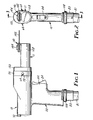
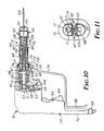
- FIG. 1 a gas operated device 10 ( Figures 1 through 9) according to the present invention for driving tools used in orthopedic surgery, such as the bone saw 11 shown in Figures 1, 2, 12 and 13, the pin or wire driver 12 shown in Figures 10 and 11, the universal chuck 13 for driving cutting tools shown in Figure 14 and the reamer driver 14 shown in Figure 15 for use in driving reamers 15 or the like, which tools 11, 12, 13 and 14 are driven by rotating a driven shaft on the tool over a predetermined speed range (i.e. driven shafts 16, 17, 18 or 19 in the tools 11 through 14, respectively).
- a predetermined speed range i.e. driven shafts 16, 17, 18 or 19 in the tools 11 through 14, respectively.
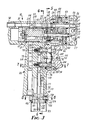
- the device 10 comprises a frame 20, an air motor 21 mounted on the frame 20 comprising a rotor 22, first and second spaced axially parallel output shafts 23 and 24 each having an output end portion 25 and 26 respectively adapted to releasably engage the driven shaft 16, 17, 18, or 19 of one of the tools 11, 12, 13, or 14, with the second shaft 24 having a through central opening 28 accessible from an end 29 of the second shaft 24 opposite its output end 26 through an opening 27 through the frame 20 partially defined by a hard steel cylindrical guide 30; means for driving the output shafts 23 and 24 from the rotor 22 to rotate both of the output shafts 23 and 24 with the second output shaft 24 rotating at a substantially slower rate of rotation than the first output shaft 23 upon rotation of the rotor 22; means for releasably attaching one of the tools 11, 12, 13, or 14 to the frame 20 with the driven shaft 16, 17, 18 or 19 of the tool in driving engagement with the output end 25 or 26 of one of the output shafts 23 and 24; and means for coupling a supply of gas under
- the means for driving the output shafts 23 and 24 from the rotor 22 includes the first output shaft 23 being fixed to (as by being an integral part of) the rotor 22 and with the rotor 22 being rotatably mounted on the frame 20 by ball bearings 31; a first drive gear 32 coaxially fixed to (as by being integrally formed with) the first output shaft 23; a ring gear 34 fixed on the frame 20 coaxially around the first drive gear 32; a plurality of planetary gears 36 having teeth engaged with the teeth of the first drive gear 32 and ring gear 34 around the first drive gear 32; a carrier 38 having a central opening through which the first output shaft 23 projects, which carrier 38 is rotatably mounted on the frame 20 by ball bearings 40 coaxially about the first output shaft 23, rotatably supports the planetary gears 36 in spaced relationship around the first drive gear 32, and has a second drive gear 42 coaxially fixed about (as by being integrally formed on) its periphery; and a driven gear 44
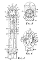
- the means for releasably attaching one of the tools 11, 12, 13 or 14 to the frame 20 with the driven shaft 16, 17, 18 or 19 of the tool in engagement with the output end portion 25 or 26 of one of the output shafts 23 and 24 comprises walls of the frame 20 defining a socket 45 having an inlet opening and being adapted to receive a portion 46, 47, 48 or 49 of a frame 50, 51, 52, or 53 of the tool 11, 12, 13, or 14 in close fitting relationship.
- Those walls include an inner wall defining an inner end surface 55 of the socket 45 opposite its inlet opening with the output shafts 23 and 24 projecting through the inner wall and the output end portions 25 and 26 of the output shafts 23 and 24 being positioned within the socket 45, and a side wall 56 fixed to and projecting from the inner wall and defining a generally oval side surface 57 for the socket 45 extending generally parallel to the axes of the output shafts 23 and 24 between the inner end surface 55 and the inlet opening of the socket 45, which generally oval side surface 57 has opposite end portions that are cylindrically arcuate about the axes of the output shafts 23 and 24.
- Means are provided for releasably attaching one of the tools 11, 12, 13 or 14 to the frame 20 of the device 10.
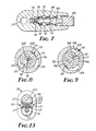
- These means comprise the side wall 56 having opposed transverse stepped through openings 58 adapted to receive locking pins 60 biased by a spring 59 to project outwardly from the frame portions 46, 47, 48 or 49 of the tools 11, 12, 13 or 14 adapted to be received in the socket 45; and release buttons 64 in the through openings 58 having inner ends 65 adjacent the socket 45 and opposite outer ends 66 accessible from the outer surface of the side wall 56 and being mounted in the through openings 58 for movement (within limits defined by pins 61 fixed in the side wall 56 through transverse openings 62 in the buttons 64) between a lockable position to which the release buttons 64 are biased by springs 54, at which lockable position the inner ends 65 of the buttons 64 are spaced from the side surface 57 of the socket 45 to receive the locking pins 60 of the tools 11, 12, 13 or 14 in the through openings 58 to lock the tools 11, 12, 13 or 14 to the device 10
- the side wall 56 is beveled outwardly adjacent the inlet opening to the socket 45 to provide a beveled surface 67 that will cam the outwardly biased locking pins 60 onto the side surface 57 when the frame portions 46, 47, 48 or 49 of the tools 11, 12, 13, or 14 are inserted into the socket 45.
- the output end portion 26 of the second output shaft 24 comprises two opposed circumferentially spaced tapered projections 63 adapted to engage between two similarly shaped spaced tapered projections 71 on the ends of the driven shafts 17, 18 and 19 of the tools 12, 13 and 14, with the tapered ends 63 and 71 causing proper alignment thereof as the second output shaft 24 and one of the driven shafts 17, 18 or 19 engage; whereas the output end portion 25 of the first output shaft 23 has a transverse slot 68 adapted to receive a transverse drive plate 69 ( Figure 12) in the driven shaft 16, which drive plate 69 is slidably mounted in a longitudinal slot diametrically across a socket in the driven shaft 16 and is biased toward the end of the shaft 16 by a spring 70 to afford improper alignment of the output end portion 25 and the drive plate 69 as the bone saw 11 engages the device 10 and subsequent engagement of the drive plate 69 with the slot 68 under the influence of the spring 70 as the first output shaft 23 is rotated by the device 10.
- the means for coupling a supply of gas under greater than atmospheric pressure to the air motor 21 to rotate its rotor 22 comprises (1) means in the form of the frame 20 and a pair of plugs 82 inserted in openings bored in the frame 20 for defining first and second passageways 72 and 73 ( Figure 4) each having inlet ends 74 and 75 respectively and having outlet ends in opposite sides of the air motor 21 for directing gas to different positions so that gas directed through the first passageway 72 into the air motor causes rotation of the rotor 22 in a first or clockwise direction as viewed in Figure 4, and gas directed through the second passageway 73 into the air motor 21 causes rotation of the rotor 22 in a second direction opposite the first direction or counterclockwise as viewed in Figure 4; (2) means in the form of the frame 20 including a generally tubular portion 77 thereof threaded into a main portion 76 of the frame 20 that defines a handle by which the device 10 is manually grasped, and an upper portion in which the air motor 21 and output shafts 23 and 24 are mounted, which tubular portion
- the main valve means comprises a pair of valve assemblies 86 and 87 each comprising (1) a housing member 88 sealed in the main portion 76 of the frame 20 by O-rings and held in place by a removable plate-like portion 91 of the frame 20 attached to its main portion 76 by a screw 92; (2) a plunger 93 axially slidably mounted in the housing member 88 and sealed in the housing member 88 by an O-ring 94, which plunger 93 is biased by a spring 95 to a position with an O-ring 96 around a head 97 on the plunger 93 in sealing engagement against a lip on the housing member 88 to prevent gas at the outlet end 79 of the inlet passageway 78 from passing into the first passageway 72 or the second passageway 73 which the valve assembly 86 or 87 controls.
- Either of the plungers 93 is movable to an open position by pivoting the trigger 84 in the appropriate direction around a pin 102 to move the plunger 93 and thereby the O-ring 96 on that plunger 93 away from its seat to allow gas under pressure to pass from the inlet passageway 78 into one of the passageways 72 or 73 to produce the desired direction of rotation of the rotor 22.
- the regulating valve means in the inlet passageway 78 comprises wall means or walls of the frame portion 77 for defining both a part of the inlet passageway 78 and further defining a guide passageway 98 extending transverse of the inlet passageway 78; a spool 99 having end portions 100 and 101 slidably mounted in the guide passageway 98 for longitudinal sliding movement and having O-rings around their peripheries to place them in airtight sliding engagement with the frame portion 77, and a central portion 104 of reduced cross section.
- the spool 99 is longitudinally slidable in the guide passageway 98 between an on position ( Figures 3 and 8) with the central portion 104 extending across the inlet passageway 78 to afford flow of gas through the inlet passageway 78; and an off position ( Figure 9) with the central portion 104 spaced from the inlet passageway 78 and the end portion 100 blocking the inlet passageway 78, with some positions of the spool 99 between its on and off positions restricting flow of gas through the inlet passageway 78; and manually operable means for positioning the spool 99 in any position including its on position and its off position and any position therebetween.
- the wall means or portion 77 of the frame 20 defining the inlet passageway 78 and the guide passageway 98 have opposite arcuate outer surfaces 106 with the guide passageway 98 opening through the outer surfaces 106.
- the end portions 100 and 101 of the spool 99 extend to at least the outer surfaces 106 and at least one of the end portions 100 or 101 projects beyond one of the outer surfaces 106 in all positions of the spool 99.
- the manually operable means for positioning the spool 99 in any position including its on and its off position and any position therebetween comprises a cam 108 rotatably mounted on the tubular portion 77 of the frame 20, having cam surfaces 109 adapted for engagement with the end portions 100 and 101 of the spool 99 for moving the spool 99 between its off and on positions upon manual rotation of the cam 108 relative to the frame 20, and a knurled cylindrical periphery facilitating manual engagement of the cam 108 to rotate it.
- the air motor 21 to which gas may be directed through the first and second passages 72 and 73 is of a known type comprising walls defining a generally cylindrical chamber 110 in which the rotor 22 is rotatably mounted about an axis spaced from the axis of the chamber 110.
- the rotor 22 has a plurality of radially extending slots in which plate-like vanes 111 are slidably positioned and will be biased by gas pressure in the motor 21 radially outwardly of the rotor 22 into slidable sealing engagement with the inner cylindrical surface defining the chamber 110.
- the bone saw 11 shown in Figures 1, 2, 12 and 13 comprises its frame 50, a first part 120 of which has the already described projecting portion 46 adapted to be received in the socket 45 of the device 10.
- the projecting portion 46 has a transverse opening or receptacle 121 in which are positioned the locking pins 60 adapted for releasable engagement with the openings 58 in the side wall 56 of the device 10, which pins 60 are biased outwardly by the spring 59 and are movable in the opening 121 within limits determined by engagement of a pin 119 anchored in the frame 50 with spaced inner surfaces of the pin 60 defined by a reduced diameter central portion 123 thereof between (1) outer positions shown at which outer ends of the pins 60 can enter the openings 58 to lock the frame 50 to the device 10, and (2) release positions with the pins 60 entirely within the opening 121 in the frame 50 at which the projecting portion 46 can be inserted in or removed from the device 10.
- the projecting portion 46 of the frame 50 also has a bore 122 adapted to provide clearance for
- the frame 50 of the bone saw includes a second part 124 having a cylindrical end 125 fixed in a receptacle in the first frame part 120 by a transverse pin 126, and having a cylindrical periphery 127 about which a third part 128 of the frame 50 is rotatably journaled.
- the third frame part 128 is retained in place by a shoulder 129 and an internal outwardly spring biased retaining ring 130 engaging the second frame part 124 on opposite ends of the periphery 127, and is restricted against free rotation about the second frame part 124 by two O-rings compressed therebetween.
- the driven shaft 16 on the bone saw 11 is rotatably mounted through a cavity defined in the first, second and third frame parts 120, 124 and 128 by two bearings 132, has an end in the projecting portion 46 carrying the transverse spring 70 biased drive plate 69 adapted to be engaged by the first output shaft 23 as has previously been described, and has an off center pin 133 projecting from its end opposite the drive plate 69.
- the pin 133 has a central axis that at all rotational positions of the driven shaft 16 intersects the axis of a drive member 134 mounted in the third frame part 128 by bearings 135 for pivotal movement about an axis at a right angle to the axis of the driven shaft 16.
- An orbiting link 136 has a concentric bearing 137 at one end engaged over the off center pin 133, and an opposite flatted end portion 138 with flats on both sides parallel to the pivot axis of the drive member 134.
- the flats on the flatted end portion 138 are closely received in a longitudinally extending slot in the drive member 134, which slot has sufficient length so that the link 136 can pivot in the slot in the plane defined by the axes of the driven shaft 16 and drive member 134.
- the drive member 134 is included in an attaching assembly 141 for releasably attaching an osteomy blade 142, which attaching assembly 141 and blade 142 are more completely described in U.S Patent No. 4,386,609 incorporated herein by reference.
- the blade 142 can be inserted or removed by depressing a locking button 144 included in the attaching assembly 141 against the bias of a spring 145.
- the third frame part 128 of the bone saw 11 may be rotated to any position around the cylindrical periphery 127 of the second frame part 124 to present the saw blade 142 at many orientations with respect to the device 10, as may be convenient during use of the bone saw 11 during surgery.
- the pin or wire driver 12 shown in Figure 10 comprises its frame 51 including the already described projecting portion 47 adapted to be received in the socket 45 of the device 10.
- the projecting portion 47 carries the locking pins 60 and their biasing spring 59, which pins 60 are adapted for releasable engagement with the openings 58 in the side wall 56 of the device 10, and has a bore 148 adapted to provide clearance for the output end portion 25 of the first output shaft 23 which does not make driving engagement with the wire driver 12.
- the driven shaft 17 on the wire driver 12 projects through and is rotatably mounted in a cavity defined in the frame 51 by two ball bearings 150.
- the driven shaft 17 has a through central opening, and has two tapered projections 71 on its end in the projecting portion 47 adapted to be engaged by the similar projections 63 on the output end portion 26 of the second output shaft 24 as has previously been described.
- On the end portion of the driven shaft 17 opposite the projections 71 is fixed (by threaded engagement) an inner portion 154 of a special chuck assembly 155 for driving pins or wires (such as a wire 153 illustrated) having drill like cutting surfaces on their leading ends.
- the inner portion 154 has a through central opening, a conically tapered outer surface 156 and three sets of three circumferentially spaced through openings from the outer surface to the central opening in which are positioned nine locking balls 158, three each of the same diameter.
- an outer portion 160 including a cap-like end part 161 having a central opening 159 through its end wall, a front cylindrical part 162 to which is threadably and fixedly engaged the end part 161 and which has a conical inner surface 163 adapted to engage the outer surfaces of the locking balls 158.
- the outer portion 160 of the chuck assembly 155 also includes a rear cylindrical part 164 adjustably threadably engaged with the front part 162 at threads 166, having an annular inwardly projecting lip 167 at its end opposite the front cylindrical part 162 within which is engaged a transversely extending cross bar 168 with a central opening, which cross bar 168 extends radially through a transverse opening 169 in the driven shaft 17.
- the cross bar 168 is biased into engagement with the lip 167 by a spring 170 compressed in the driven shaft 17 between the inner portion 154 and a hollow cylindrical spacer 172 between the spring 170 and cross bar 168, thereby affording relative adjustment of the front and rear cylindrical parts 162 and 164 at the threads 166 and biasing the outer portion 160 of the chuck assembly 155 to its position relative to its inner portion 154 with the conical surface 163 spaced at its maximum possible distance from the locking balls 158.
- a lever 174 is pivotably mounted on the frame 51 at a pin 175 and has a forked end part 176 engaging the outer race of a ball bearing 177 having its inner race fixed about the periphery of the rear cylindrical part 164 by a spacer 178 and snap ring 179.
- the lever 174 has an end portion 180 disposed adjacent and generally parallel to the front face of the handle of the device 10, which end portion 180 is adapted to be engaged by a user of the device 10 to move the lever 174 between a release position spaced from the handle at which the spring 170 provides the maximum possible separation between the conical surface 163 and the locking balls 158, and an engage position adjacent the handle (shown in Figure 10) at which the lever 174 moves the outer portion 160 of the chuck assembly 155 away from the frame 51 of the wire driver 12 by a predetermined amount to decrease that spacing between the conical surface 163 and locking balls 158.
- a user inserts the wire 153 through the central opening 159 in the end part 161, between the locking balls 158 in the central opening of the inner portion 154, and through the central opening in the spring 170, the spacer 172, the cross bar 168, the driven shaft 17, the second output shaft 24, and through the aligned opening 27 and guide 30 in the frame 20.
- the user then rotates the front cylindrical part 162 into the rear cylindrical part 164 of the outer portion 160 until its conical inner surface 163 presses the locking balls 158 against the wire 153 with the lever 174 in its release position.
- the user can then activate the device 10 by pulling the trigger 84 and move the lever 174 to its engage position by pulling its end portion 180 toward the handle to rotate the wire 153 from the chuck assembly 155, and can allow movement of the lever 174 to its release position under the influence of the spring 170 by releasing end portion 180 of the lever 174 to afford movement of the chuck assembly along the wire 153 to again engage a new portion thereof by movement of the lever 174 back to its engage position as is needed to drive the wire 153 into an object, such as a bone.
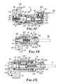
- the universal chuck 13 shown in Figure 14 comprises its frame 52 including the already described projecting portion 48 adapted to be received in the socket 45 of the device 10, which projecting portion 48 carries the locking pins 60 adapted for releasable engagement with the openings 58 in the side wall 56 of the device 10, and has a bore 183 adapted to provide clearance for the output end portion 25 of the first output shaft 23 which does not make driving engagement with the universal chuck 13.
- the driven shaft 18 of the universal chuck 13 projects through and is rotatably mounted in a cavity defined in the frame 52 by two ball bearings 184.
- the driven shaft 18 has a through central opening, and has two tapered projections 71 on its end in the projecting portion 48 adapted to be engaged by the similar projections 63 on the second output shaft 24 as has previously been described.
- the end portion of the driven shaft 18 opposite the projections 63 provides an inner portion 185 of a special chuck assembly 186 adapted for engaging tools such as the rotary cutter 188 (e.g., a drill) shown in phantom outline in Figure 14 which have driven ends of the types commercially designated "Hudson" or "Zimmer”TM style.
- the inner portion 185 has through radially extending passageways from its outer surface to its central opening in which are positioned locking balls 189.
- a sleeve-like outer portion 190 to which are fixed opposed inwardly projecting pins 191 received in opposed longitudinal slots in the inner portion 185 and engaging the end of a compressed coil spring 192 centerally located in the driven shaft 18 and having its opposite end supported against an end wall of a socket in the driven shaft 18 to bias the sleeve-like outer portion 190 to a position at which its inner surface engages the outer surfaces of the locking balls 189 and can lock the balls 189 in engagement with recesses in the driven end of the cutter 188.
- the sleeve-like outer portion 190 can be manually moved axially relative to the driven shaft 18 to further compress the spring 192 and position grooves 194 on its inner surface adjacent the locking balls 189 so that they may move radially outwardly of the inner portion 185 and out of the recesses in the cutter 188 so that the cutter 188 may be removed or inserted.
- a user moves the sleeve-like outer portion 190 axially toward the frame 52 so that the locking balls 189 can move outwardly into the grooves 194, inserts the driven end of a tool such as the cutter 188 into the central opening of the inner portion 185, and releases the sleeve-like outer portion 190 so that the spring 192 positions its inner surface to lock the locking balls 189 in recesses in the tool thereby locking it in place.
- the driven shaft 18 including the inner portion 185 of the chuck assembly 186 and the spring 192 provide a through central opening so that a guide wire already positioned in an object (e.g., in a bone) can be fed through a central opening in the tool, the universal chuck 13 and the second output shaft 24 of the device 10, the device 10 can be activated, and the tool can be moved along the guide wire which then acts as a guide for the tool as it is moved through the object.
- the reamer driver 14 shown in Figure 15 comprises its frame 53 including the already described projecting portion 49 adapted to be received in the socket 45 of the device 10, which projecting portion 49 carries the locking pins 60 adapted for releasable engagement with the openings 58 in the side wall 56 of the device 10, and has a bore 204 adapted to provide clearance for the output end portion 25 of the first output shaft 23 which does not make driving engagement with the reamer driver 14.
- the driven shaft 19 of the reamer driver 14 projects through and is rotatably mounted in a cavity defined in the frame 53 by a ball bearing 205.
- the driven shaft 19 has a through central opening, and has two tapered projections 71 on its end in the projecting portion 49 adapted to be engaged by similar projections 63 on the second output shaft 24 as has previously been described.
- a drive gear 207 is fixed on (as by being integrally formed with) the end portion of the driven shaft 19 opposite the projections 71.
- a ring gear 208 is fixed on the frame 53 coaxially around the drive gear 207.
- a plurality of planetary gears 209 having teeth engaged with the teeth of the drive gear 207 and ring gear 208 are positioned around the driver gear 207, and are rotatably supported on a carrier 210 having a through central opening, which carrier 210 is rotatably mounted on the frame 53 by two ball bearings 211.
- the end of the carrier 210 opposite the planetary gears 209 provides an inner portion 212 of a special chuck assembly 214 similar to the chuck assembly 186 for engaging tools such as the reamer 15 shown in phantom outline in Figure 15 which have driven ends of the types commercially designated "Hudson” or "Zimmer”TM style.
- the inner portion 212 has through radially extending passageways from its outer surface to its central opening in which are positioned locking balls 218.
- a sleeve-like outer portion 220 to which are fixed opposed inwardly projecting pins 222 received in opposed longitudinal slots in the inner portion 212 and engaging the end of a compressed coil spring 224 centrally located in the carrier 210 and having its opposite end supported adjacent an end of the driven shaft 19 journaled in the carrier 210 to bias the sleeve-like outer portion 220 to a position at which its inner surface engages the surfaces of the locking balls 218 and can lock the balls 218 in engagement with recesses in the driven end of the reamer 15.
- the sleeve-like outer portion 220 can be manually moved axially relative to the driven shaft 19 to further compress the spring 224 and position grooves 226 on its inner surface adjacent the locking balls 218 so that they may move radially outwardly out of recesses in the reamer 15 and the reamer 15 may be removed or inserted.
- the reamer driver 14 is used in the same way as the universal chuck 13 described above, the only significant difference being that the output speed at the chuck assembly 214 will be significantly less for a given speed at the second output shaft 24 of the device 10 as is more appropriate for driving a reamer due to the gear reduction caused by the gears 207, 208 and 209 (e.g., about a 4/1 gear reduction).
- the main portion 76 of the frame 20 is of aluminum coated on its surface with a dark colored (e.g., dark gray) hard anodized coating, and having a dark colored (e.g., black) coating of tetrafluoroethylene over the anodized coating.
- a dark colored (e.g., dark gray) hard anodized coating and having a dark colored (e.g., black) coating of tetrafluoroethylene over the anodized coating.
- a method has been found for forming crisp white indicia (e.g., printed tradenames or instructions) on the aluminum frame 20 after those coatings are applied by removing with a laser precise predetermined portions of the coating in the shape of the indicia. This results in forming a white aluminum oxide coating on the frame 20 in the areas from which the coating has been removed that is very clearly visible through the remainder of the dark coating.
Landscapes
- Health & Medical Sciences (AREA)
- Life Sciences & Earth Sciences (AREA)
- Surgery (AREA)
- Engineering & Computer Science (AREA)
- Medical Informatics (AREA)
- General Health & Medical Sciences (AREA)
- Orthopedic Medicine & Surgery (AREA)
- Veterinary Medicine (AREA)
- Biomedical Technology (AREA)
- Heart & Thoracic Surgery (AREA)
- Public Health (AREA)
- Molecular Biology (AREA)
- Animal Behavior & Ethology (AREA)
- Nuclear Medicine, Radiotherapy & Molecular Imaging (AREA)
- Dentistry (AREA)
- Oral & Maxillofacial Surgery (AREA)
- Mechanical Engineering (AREA)
- Wood Science & Technology (AREA)
- Forests & Forestry (AREA)
- Surgical Instruments (AREA)
- Orthopedics, Nursing, And Contraception (AREA)
- Portable Power Tools In General (AREA)
Priority Applications (1)
| Application Number | Priority Date | Filing Date | Title |
|---|---|---|---|
| AT87302789T ATE89148T1 (de) | 1986-04-03 | 1987-03-31 | Antriebsgeraet fuer werkzeuge in der orthopaedischen chirurgie. |
Applications Claiming Priority (2)
| Application Number | Priority Date | Filing Date | Title |
|---|---|---|---|
| US06/847,483 US4736742A (en) | 1986-04-03 | 1986-04-03 | Device for driving tools used in orthopedic surgery |
| US847483 | 2004-05-17 |
Publications (3)
| Publication Number | Publication Date |
|---|---|
| EP0240310A2 true EP0240310A2 (de) | 1987-10-07 |
| EP0240310A3 EP0240310A3 (en) | 1988-08-03 |
| EP0240310B1 EP0240310B1 (de) | 1993-05-12 |
Family
ID=25300738
Family Applications (1)
| Application Number | Title | Priority Date | Filing Date |
|---|---|---|---|
| EP87302789A Expired - Lifetime EP0240310B1 (de) | 1986-04-03 | 1987-03-31 | Antriebsgerät für Werkzeuge in der orthopädischen Chirurgie |
Country Status (10)
| Country | Link |
|---|---|
| US (1) | US4736742A (de) |
| EP (1) | EP0240310B1 (de) |
| JP (1) | JP2625117B2 (de) |
| KR (1) | KR950014960B1 (de) |
| AT (1) | ATE89148T1 (de) |
| CA (1) | CA1287530C (de) |
| DE (1) | DE3785790T2 (de) |
| ES (1) | ES2040249T3 (de) |
| HK (1) | HK64495A (de) |
| MX (1) | MX165754B (de) |
Cited By (2)
| Publication number | Priority date | Publication date | Assignee | Title |
|---|---|---|---|---|
| EP0700273A4 (de) * | 1993-05-11 | 1997-04-02 | Jack W Romano | Apparat zum drillen einer gebogenen bohrung |
| CN113558714A (zh) * | 2021-06-30 | 2021-10-29 | 河南省洛阳正骨医院(河南省骨科医院) | 一种骨科手术用指骨锯 |
Families Citing this family (60)
| Publication number | Priority date | Publication date | Assignee | Title |
|---|---|---|---|---|
| JPH063550Y2 (ja) * | 1988-10-26 | 1994-02-02 | オリンパス光学工業株式会社 | 外科用切除器具 |
| US5057112A (en) * | 1990-01-04 | 1991-10-15 | Intermedics Orthopedics, Inc. | Pneumatically powered orthopedic broach |
| USD337160S (en) | 1991-01-11 | 1993-07-06 | Stryker Corporation | Sagittal saw blade base |
| US5263972A (en) * | 1991-01-11 | 1993-11-23 | Stryker Corporation | Surgical handpiece chuck and blade |
| USD343247S (en) | 1992-02-03 | 1994-01-11 | Stryker Corporation | Surgical saw blade base |
| USD346318S (en) | 1993-01-21 | 1994-04-26 | Stryker Corporation | Sagittal saw blade base |
| USD348194S (en) | 1993-04-01 | 1994-06-28 | Stryker Corporation | Sagittal saw blade base |
| US5468247A (en) * | 1993-05-26 | 1995-11-21 | Stryker Corporation | Saw blade for powered medical handpiece |
| USD351907S (en) | 1993-05-26 | 1994-10-25 | Stryker Corporation | Slotted cast cutter blade base |
| USD355344S (en) | 1994-05-10 | 1995-02-14 | Stryker Corporation | Cast cutter handpiece |
| USD364463S (en) | 1994-06-10 | 1995-11-21 | Minnesota Mining And Manufacturing Company | Orthopedic surgical instrument |
| US5553675A (en) * | 1994-06-10 | 1996-09-10 | Minnesota Mining And Manufacturing Company | Orthopedic surgical device |
| US5728118A (en) * | 1995-03-29 | 1998-03-17 | Linvatec Corporation | Apparatus and method for harvesting a bone-tendon-bone ligament graft |
| USD379795S (en) * | 1995-11-13 | 1997-06-10 | Minnesota Mining And Manufacturing Company | Battery housing for an orthopedic surgical device |
| US5697158A (en) * | 1995-12-21 | 1997-12-16 | Minnesota Mining And Manufacturing Company | Orthopedic surgical device having a rotatable portion and lock |
| US5741263A (en) * | 1997-04-18 | 1998-04-21 | Midas Rex Pneumatic Tools, Inc. | Mutiple flat quick release coupling |
| US5893851A (en) * | 1997-04-18 | 1999-04-13 | Midas Rex Pneumatic Tools, Inc. | Multiple chuck resecting tool |
| US5902306A (en) * | 1997-05-01 | 1999-05-11 | Linvatec Corporation | Surgical wire driver with one-handed gripping attachment |
| US6656626B1 (en) * | 1999-06-01 | 2003-12-02 | Porter-Cable Corporation | Cordless power tool battery release mechanism |
| US6244797B1 (en) * | 1999-10-27 | 2001-06-12 | Black & Decker Inc. | Router keyless chuck |
| JP3950989B2 (ja) * | 1999-12-24 | 2007-08-01 | リー,ヒ−ヨン | 下あご等の顔面骨の手術器具 |
| US6729413B2 (en) * | 2001-08-24 | 2004-05-04 | Black & Decker Inc. | Power tool with battery pack ejector |
| US20080177268A1 (en) * | 2002-02-14 | 2008-07-24 | Wolfgang Daum | Minimally-Invasive Approach to Bone-Obstructed Soft Tissue |
| US7682362B2 (en) * | 2005-02-01 | 2010-03-23 | Smith & Nephew, Inc. | Lockable orientation stylus |
| US8834473B2 (en) * | 2005-02-01 | 2014-09-16 | Smith & Nephew, Inc. | Lockable orientation instrument assembly |
| US7597699B2 (en) * | 2005-07-25 | 2009-10-06 | Rogers William G | Motorized surgical handpiece |
| AU2006299438B9 (en) | 2005-10-03 | 2013-07-18 | Smith & Nephew, Inc. | Locking instrument assembly |
| USD580725S1 (en) | 2006-01-06 | 2008-11-18 | Milwaukee Electric Tool Corporation | Power tool, such as a drill |
| US20080044244A1 (en) * | 2006-08-15 | 2008-02-21 | Keffer Gary L | Veterinary precision fixation device and method of using the same |
| US20110208200A1 (en) * | 2006-08-15 | 2011-08-25 | Gary Keffer | Veterinary precision fixation device and method of using the same |
| EP2214615A4 (de) | 2007-11-13 | 2012-04-25 | Orthopediatrics Corp | Gipsentfernungssystem |
| EP2303148B1 (de) | 2008-06-26 | 2017-02-22 | Wayne Anderson | Tiefenkontrollierbare medizinische antriebsvorrichtungen |
| WO2011123703A1 (en) * | 2010-03-31 | 2011-10-06 | Smart Medical Devices, Inc. | Depth controllable and measurable medical driver devices |
| US8696511B2 (en) * | 2010-10-29 | 2014-04-15 | Warsaw Orthopedic, Inc. | Surgical instrument with plantary gear system |
| EP2750620B1 (de) | 2011-09-02 | 2017-04-26 | Stryker Corporation | Chirurgisches instrument mit einem von einem gehäuse weggehenden schneidzubehör und aktoren zur definition der position des schneidzubehörs in relation zum gehäuse |
| US10022174B2 (en) * | 2012-06-04 | 2018-07-17 | Depuy Mitek, Llc | Methods and devices for surgical guide pin placement |
| US11309764B2 (en) | 2012-06-26 | 2022-04-19 | DePuy Synthes Products, Inc. | Systems and apparatus for providing motor protection in a power tool and method of manufacturing the same |
| US10617431B2 (en) * | 2012-06-26 | 2020-04-14 | DePuy Synthes Products, Inc. | Systems and apparatus for providing motor protection in a power tool and method of manufacturing the same |
| US9615816B2 (en) * | 2013-03-15 | 2017-04-11 | Vidacare LLC | Drivers and drive systems |
| US9687257B2 (en) | 2014-06-04 | 2017-06-27 | Zimmer Surgical, Inc. | Pin wire driver device |
| US20160000449A1 (en) * | 2014-07-02 | 2016-01-07 | Peter M. Aman | Sterile ready-to-use surgical tool and attachment system |
| US10993729B1 (en) * | 2014-07-02 | 2021-05-04 | Insurgical, Inc. | Sterile ready-to-use surgical tool and attachment system |
| JP6423224B2 (ja) * | 2014-09-30 | 2018-11-14 | 日東工器株式会社 | 弁装置及び弁装置を備えたエア工具 |
| CN105147355A (zh) * | 2015-10-23 | 2015-12-16 | 诺鑫(南通)医疗技术有限公司 | 便携式医用骨锯驱动机构 |
| WO2017139674A1 (en) | 2016-02-12 | 2017-08-17 | Smart Medical Devices, Inc. | Driving devices and methods for determining material strength in real-time |
| US10980522B2 (en) | 2016-10-18 | 2021-04-20 | Piper Access, Llc | Intraosseous access devices, systems, and methods |
| ES2880417T3 (es) | 2017-03-07 | 2021-11-24 | Piper Access Llc | Elementos de protección de seguridad para instrumentos alargados y sistemas relacionados |
| AU2018231237B2 (en) | 2017-03-10 | 2023-03-30 | Piper Access, Llc. | Securement devices, systems, and methods |
| CN118340552A (zh) | 2018-02-20 | 2024-07-16 | 派柏阿克塞斯有限责任公司 | 钻孔装置及相关的方法 |
| CA3115237A1 (en) | 2018-10-03 | 2020-04-09 | Stryker Corporation | Chuck for a wire driver |
| AU2020315615B2 (en) | 2019-07-15 | 2026-01-29 | Stryker Corporation | Robotic hand-held surgical instrument systems and methods |
| CN212879505U (zh) | 2019-09-27 | 2021-04-06 | 巴德阿克塞斯系统股份有限公司 | 骨内进入装置 |
| US11517349B2 (en) | 2019-09-27 | 2022-12-06 | Bard Access Systems, Inc. | Autovance feature of an intraosseous device |
| US11759235B2 (en) | 2019-09-27 | 2023-09-19 | Bard Access Systems, Inc. | Constant-torque intraosseous access devices and methods thereof |
| WO2021216521A1 (en) | 2020-04-21 | 2021-10-28 | Bard Access Systems , Inc. | Reusable push-activated intraosseous access device |
| CN113749724B (zh) | 2020-06-03 | 2026-01-13 | 巴德阿克塞斯系统股份有限公司 | 包括感测闭塞器的骨内装置 |
| WO2022046790A1 (en) | 2020-08-25 | 2022-03-03 | Bard Access Systems, Inc. | Angled intraosseous access system |
| CN216167682U (zh) | 2020-09-01 | 2022-04-05 | 巴德阿克塞斯系统股份有限公司 | 用于进入髓腔的可折叠或可缩回骨内进入系统 |
| WO2022056005A1 (en) | 2020-09-09 | 2022-03-17 | Bard Access Systems, Inc. | Aspiration apparatus for intraosseous access system |
| CN114903553A (zh) | 2021-02-08 | 2022-08-16 | 巴德阿克塞斯系统股份有限公司 | 骨内进入系统和用于钻入穿过骨骼的方法 |
Family Cites Families (7)
| Publication number | Priority date | Publication date | Assignee | Title |
|---|---|---|---|---|
| US2909949A (en) * | 1958-05-02 | 1959-10-27 | James C Winslow | Power drill with work holding device and spacing means |
| US3136563A (en) * | 1960-09-29 | 1964-06-09 | Sundstrand Corp | Tool supporting adapter |
| CH477870A (de) * | 1968-12-06 | 1969-09-15 | Synthes Ag | Pressluftbohrmaschine |
| US3752241A (en) * | 1971-06-29 | 1973-08-14 | Minnesota Mining & Mfg | Pneumatic tool |
| US4109735A (en) * | 1975-01-15 | 1978-08-29 | Minnesota Mining And Manufacturing Company | Rotary surgical driver |
| US4289131A (en) * | 1979-05-17 | 1981-09-15 | Ergo Instruments, Inc. | Surgical power tool |
| JP4022105B2 (ja) | 2002-06-27 | 2007-12-12 | 京セラ株式会社 | 多層配線基板の製造方法 |
-
1986
- 1986-04-03 US US06/847,483 patent/US4736742A/en not_active Expired - Lifetime
-
1987
- 1987-03-17 CA CA000532226A patent/CA1287530C/en not_active Expired - Lifetime
- 1987-03-20 MX MX005659A patent/MX165754B/es unknown
- 1987-03-31 DE DE87302789T patent/DE3785790T2/de not_active Expired - Fee Related
- 1987-03-31 EP EP87302789A patent/EP0240310B1/de not_active Expired - Lifetime
- 1987-03-31 ES ES198787302789T patent/ES2040249T3/es not_active Expired - Lifetime
- 1987-03-31 AT AT87302789T patent/ATE89148T1/de not_active IP Right Cessation
- 1987-04-02 JP JP62082196A patent/JP2625117B2/ja not_active Expired - Lifetime
- 1987-04-02 KR KR1019870003110A patent/KR950014960B1/ko not_active Expired - Fee Related
-
1995
- 1995-04-27 HK HK64495A patent/HK64495A/en not_active IP Right Cessation
Cited By (3)
| Publication number | Priority date | Publication date | Assignee | Title |
|---|---|---|---|---|
| EP0700273A4 (de) * | 1993-05-11 | 1997-04-02 | Jack W Romano | Apparat zum drillen einer gebogenen bohrung |
| CN113558714A (zh) * | 2021-06-30 | 2021-10-29 | 河南省洛阳正骨医院(河南省骨科医院) | 一种骨科手术用指骨锯 |
| CN113558714B (zh) * | 2021-06-30 | 2022-06-10 | 河南省洛阳正骨医院(河南省骨科医院) | 一种骨科手术用指骨锯 |
Also Published As
| Publication number | Publication date |
|---|---|
| ATE89148T1 (de) | 1993-05-15 |
| ES2040249T3 (es) | 1993-10-16 |
| CA1287530C (en) | 1991-08-13 |
| JPS62236686A (ja) | 1987-10-16 |
| HK64495A (en) | 1995-05-05 |
| EP0240310B1 (de) | 1993-05-12 |
| DE3785790T2 (de) | 1993-10-21 |
| JP2625117B2 (ja) | 1997-07-02 |
| MX165754B (es) | 1992-12-03 |
| KR870009700A (ko) | 1987-11-30 |
| EP0240310A3 (en) | 1988-08-03 |
| DE3785790D1 (de) | 1993-06-17 |
| KR950014960B1 (ko) | 1995-12-20 |
| US4736742A (en) | 1988-04-12 |
Similar Documents
| Publication | Publication Date | Title |
|---|---|---|
| EP0240310B1 (de) | Antriebsgerät für Werkzeuge in der orthopädischen Chirurgie | |
| US4834092A (en) | Device for driving tools used in orthopedic surgery | |
| US5697158A (en) | Orthopedic surgical device having a rotatable portion and lock | |
| EP1302282B1 (de) | Pneumatisches Handwerkzeug mit Steuerventil | |
| US5458603A (en) | Elongated drive tool for prosthesis in body cavity | |
| US3752241A (en) | Pneumatic tool | |
| US4674500A (en) | Sheathed knife instrument | |
| US6158528A (en) | Hand-held pneumatic rotary drive device | |
| US3835858A (en) | Surgical air drill | |
| US4109735A (en) | Rotary surgical driver | |
| US3734652A (en) | Pneumatically powered device | |
| US3439422A (en) | Air tool | |
| US20090270899A1 (en) | Surgical tool system | |
| JPH08215202A (ja) | 安全インタロック付き外科用切断器具 | |
| US5542846A (en) | Dental tool chuck | |
| EP2129303B1 (de) | Antriebsanordnung für ein chirurgisches instrument | |
| US5718582A (en) | Dental tool chuck | |
| US4806730A (en) | Method of forming crisp white indicia in aluminum | |
| US5911578A (en) | Head assembly for a medical handpiece | |
| US3250005A (en) | Dental tool and control apparatus | |
| WO1995022934A1 (en) | Surgical chisel tool and method | |
| US3423068A (en) | Pneumatically driven surgical instrument and control therefor | |
| NO790630L (no) | Tannlegeinstrument drevet av trykkluftmotor | |
| GB2463522A (en) | Controlled feed reamer and single pass cutter | |
| WO2001056749A2 (en) | Hand-held pneumatic rotary drive device having an adjustable air exhaust |
Legal Events
| Date | Code | Title | Description |
|---|---|---|---|
| PUAI | Public reference made under article 153(3) epc to a published international application that has entered the european phase |
Free format text: ORIGINAL CODE: 0009012 |
|
| AK | Designated contracting states |
Kind code of ref document: A2 Designated state(s): AT CH DE ES FR GB IT LI NL SE |
|
| PUAL | Search report despatched |
Free format text: ORIGINAL CODE: 0009013 |
|
| AK | Designated contracting states |
Kind code of ref document: A3 Designated state(s): AT CH DE ES FR GB IT LI NL SE |
|
| 17P | Request for examination filed |
Effective date: 19890202 |
|
| 17Q | First examination report despatched |
Effective date: 19911127 |
|
| ITF | It: translation for a ep patent filed | ||
| GRAA | (expected) grant |
Free format text: ORIGINAL CODE: 0009210 |
|
| AK | Designated contracting states |
Kind code of ref document: B1 Designated state(s): AT CH DE ES FR GB IT LI NL SE |
|
| REF | Corresponds to: |
Ref document number: 89148 Country of ref document: AT Date of ref document: 19930515 Kind code of ref document: T |
|
| REF | Corresponds to: |
Ref document number: 3785790 Country of ref document: DE Date of ref document: 19930617 |
|
| ET | Fr: translation filed | ||
| REG | Reference to a national code |
Ref country code: ES Ref legal event code: FG2A Ref document number: 2040249 Country of ref document: ES Kind code of ref document: T3 |
|
| EAL | Se: european patent in force in sweden |
Ref document number: 87302789.0 |
|
| PGFP | Annual fee paid to national office [announced via postgrant information from national office to epo] |
Ref country code: SE Payment date: 19980219 Year of fee payment: 12 |
|
| PGFP | Annual fee paid to national office [announced via postgrant information from national office to epo] |
Ref country code: NL Payment date: 19980223 Year of fee payment: 12 Ref country code: AT Payment date: 19980223 Year of fee payment: 12 |
|
| PGFP | Annual fee paid to national office [announced via postgrant information from national office to epo] |
Ref country code: CH Payment date: 19980309 Year of fee payment: 12 |
|
| PGFP | Annual fee paid to national office [announced via postgrant information from national office to epo] |
Ref country code: ES Payment date: 19980317 Year of fee payment: 12 |
|
| PG25 | Lapsed in a contracting state [announced via postgrant information from national office to epo] |
Ref country code: LI Free format text: LAPSE BECAUSE OF NON-PAYMENT OF DUE FEES Effective date: 19990331 Ref country code: CH Free format text: LAPSE BECAUSE OF NON-PAYMENT OF DUE FEES Effective date: 19990331 Ref country code: AT Free format text: LAPSE BECAUSE OF NON-PAYMENT OF DUE FEES Effective date: 19990331 |
|
| PG25 | Lapsed in a contracting state [announced via postgrant information from national office to epo] |
Ref country code: SE Free format text: LAPSE BECAUSE OF NON-PAYMENT OF DUE FEES Effective date: 19990401 |
|
| PG25 | Lapsed in a contracting state [announced via postgrant information from national office to epo] |
Ref country code: ES Free format text: LAPSE BECAUSE OF EXPIRATION OF PROTECTION Effective date: 19990405 |
|
| PG25 | Lapsed in a contracting state [announced via postgrant information from national office to epo] |
Ref country code: NL Free format text: LAPSE BECAUSE OF NON-PAYMENT OF DUE FEES Effective date: 19991001 |
|
| REG | Reference to a national code |
Ref country code: CH Ref legal event code: PL |
|
| NLV4 | Nl: lapsed or anulled due to non-payment of the annual fee |
Effective date: 19991001 |
|
| EUG | Se: european patent has lapsed |
Ref document number: 87302789.0 |
|
| REG | Reference to a national code |
Ref country code: ES Ref legal event code: FD2A Effective date: 20010601 |
|
| REG | Reference to a national code |
Ref country code: GB Ref legal event code: IF02 |
|
| PGFP | Annual fee paid to national office [announced via postgrant information from national office to epo] |
Ref country code: GB Payment date: 20040205 Year of fee payment: 18 |
|
| PGFP | Annual fee paid to national office [announced via postgrant information from national office to epo] |
Ref country code: FR Payment date: 20040302 Year of fee payment: 18 |
|
| PGFP | Annual fee paid to national office [announced via postgrant information from national office to epo] |
Ref country code: DE Payment date: 20040331 Year of fee payment: 18 |
|
| PG25 | Lapsed in a contracting state [announced via postgrant information from national office to epo] |
Ref country code: IT Free format text: LAPSE BECAUSE OF NON-PAYMENT OF DUE FEES;WARNING: LAPSES OF ITALIAN PATENTS WITH EFFECTIVE DATE BEFORE 2007 MAY HAVE OCCURRED AT ANY TIME BEFORE 2007. THE CORRECT EFFECTIVE DATE MAY BE DIFFERENT FROM THE ONE RECORDED. Effective date: 20050331 Ref country code: GB Free format text: LAPSE BECAUSE OF NON-PAYMENT OF DUE FEES Effective date: 20050331 |
|
| PG25 | Lapsed in a contracting state [announced via postgrant information from national office to epo] |
Ref country code: DE Free format text: LAPSE BECAUSE OF NON-PAYMENT OF DUE FEES Effective date: 20051001 |
|
| GBPC | Gb: european patent ceased through non-payment of renewal fee |
Effective date: 20050331 |
|
| PG25 | Lapsed in a contracting state [announced via postgrant information from national office to epo] |
Ref country code: FR Free format text: LAPSE BECAUSE OF NON-PAYMENT OF DUE FEES Effective date: 20051130 |
|
| REG | Reference to a national code |
Ref country code: FR Ref legal event code: ST Effective date: 20051130 |
|
| PLBE | No opposition filed within time limit |
Free format text: ORIGINAL CODE: 0009261 |
|
| STAA | Information on the status of an ep patent application or granted ep patent |
Free format text: STATUS: NO OPPOSITION FILED WITHIN TIME LIMIT |