EP0240170B1 - Plattenkassette - Google Patents
Plattenkassette Download PDFInfo
- Publication number
- EP0240170B1 EP0240170B1 EP87301857A EP87301857A EP0240170B1 EP 0240170 B1 EP0240170 B1 EP 0240170B1 EP 87301857 A EP87301857 A EP 87301857A EP 87301857 A EP87301857 A EP 87301857A EP 0240170 B1 EP0240170 B1 EP 0240170B1
- Authority
- EP
- European Patent Office
- Prior art keywords
- disc
- hub
- filler
- positioning
- disk
- Prior art date
- Legal status (The legal status is an assumption and is not a legal conclusion. Google has not performed a legal analysis and makes no representation as to the accuracy of the status listed.)
- Expired
Links
Images
Classifications
-
- G—PHYSICS
- G11—INFORMATION STORAGE
- G11B—INFORMATION STORAGE BASED ON RELATIVE MOVEMENT BETWEEN RECORD CARRIER AND TRANSDUCER
- G11B23/00—Record carriers not specific to the method of recording or reproducing; Accessories, e.g. containers, specially adapted for co-operation with the recording or reproducing apparatus ; Intermediate mediums; Apparatus or processes specially adapted for their manufacture
- G11B23/0014—Record carriers not specific to the method of recording or reproducing; Accessories, e.g. containers, specially adapted for co-operation with the recording or reproducing apparatus ; Intermediate mediums; Apparatus or processes specially adapted for their manufacture record carriers not specifically of filamentary or web form
- G11B23/0021—Record carriers not specific to the method of recording or reproducing; Accessories, e.g. containers, specially adapted for co-operation with the recording or reproducing apparatus ; Intermediate mediums; Apparatus or processes specially adapted for their manufacture record carriers not specifically of filamentary or web form discs
- G11B23/0028—Details
- G11B23/0035—Details means incorporated in the disc, e.g. hub, to enable its guiding, loading or driving
-
- G—PHYSICS
- G11—INFORMATION STORAGE
- G11B—INFORMATION STORAGE BASED ON RELATIVE MOVEMENT BETWEEN RECORD CARRIER AND TRANSDUCER
- G11B23/00—Record carriers not specific to the method of recording or reproducing; Accessories, e.g. containers, specially adapted for co-operation with the recording or reproducing apparatus ; Intermediate mediums; Apparatus or processes specially adapted for their manufacture
- G11B23/02—Containers; Storing means both adapted to cooperate with the recording or reproducing means
- G11B23/03—Containers for flat record carriers
- G11B23/0301—Details
- G11B23/0312—Driving features
Definitions
- This invention relates to a disk cartridge encasing disk such as a magnetic disk, an optical disk, etc., and more particularly to an improvement in the material of a hub to be fixed at the center of the disk to rotate the disk.
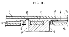
- the hub as shown in Fig. 9, comprises a control ring 19 made from a plastic and destined for defining the free movement of a disk 2 in a case 1, and a flange 18 made from a thin magnetic stainless steel sheet and destined for being chucked by magnetic attraction, the control ring 19 and the flange 18 being integrally built up by outsert molding.
- the control ring 19 has, on its inside surface, a positioning surface for centering with respect to the driving shaft S for disk drive, and the flange 18 has, on its plate surface, a driving hole 23 which is engaged with a driving pin P on the driving shaft.
- the flange 18 and the control ring 19 are so integrated that the flange 18 may cover the opening at one side of the control ring 19 .
- the control ring When there is a large difference in the coefficient of thermal expansion between the control ring and the flange, the control ring has a larger contraction ratio when solidified, and thus the plate surface of the flange will undergo warping deformation in the plate thickness direction owing to the internal stress developed by the solidification. Once the flatness of the plate surface of the flange is deteriorated by the warping deformation, track deviation or disk flapping is liable to occur while the disk is used, and will be a fatal drawback for a high density recording disk.
- a hub obtained by the said outsert molding is applied to a disk cartridge of relatively small size, it is necessary to prepare a smaller hub to meet the size-down of a disk diameter, but there has been a restriction with respect to the mechanical strength to make the sizes of a positioning or control, ring, for example, thickness, ring width, etc. smaller. That is, the disk can be made smaller in sizes, but it has been impossible to make the hub smaller in size than a given limit value. Furthermore, the positioning surface on the control ring is liable to undergo attrition by the driving shaft, thereby giving a poor centering. When the control ring is a plastic moulded article, it is hard to obtain a positioning surface with good durability and reliability against attrition over a long time.
- GB-A-2 127 206 discloses a disc cartridge in accordance with the prior art portion of claim 1. This prior construction avoids use of a metal plate filling the centre of the positioning ring and thus gives no assistance to avoiding the difficulties arising from deformation of the metal plate overcome by the present invention as characterised in claim 1.
- the present invention has as an object to provide a magnetic disc hub which comprises a positioning ring made of a plastic and a plate made of a thin metal sheet, which can be produced in a mass production scale with a high reliability and can meet requirements for the plane precision of the plate, good location of the disc being provided by engagement of a disc drive shaft with the metal plate, not possible where an annular flange is used, there also being provided good mechanical strength of the positioning ring.
- the desired hub of the present invention can be produced by outsert moulding a control ring from a compound plastic containing a filler, particularly a reinforcing filler, with the filler being provided in a quantity to modify and reduce the moulding shrinkage of the compound plastic, when mixed with the filler, during moulding of the plate.
- the plastic base material can be selected mainly from thermoplastic resins such as polyacetal, nylon, polybutylene terephthalate, polyester, polypropylene, polyethylene, polyfluoroethylene, etc.
- the filler can be selected from potassium titanate, calcium carbonate, graphite, talc, glass fibers, etc., and can be in a granular, whisker or plate shape. 5 to 10% by weight, preferably 10 to 30% by weight, of the fillers is contained in the compound plastic. Below 5% by weight of the filler, the mold shrinkage will be increased, and the heat resistance will be lowered. That is, when the ambient temperature exceeds 60°C, the molded article is liable to be deformed, and the mechanical strength will be lowered, causing breakages or wearing. Above 40% by weight of the filler, the flowability of the molten compound plastic will be lowered, causing poor molding, and considerably deteriorating the impact resistance. That is, cracks are liable to develop.
- the molding shrinkage can be defined by the numerical value obtained according to the following equation, and will be hereinafter based on this value:
- the molding shrinkage is not more than 1.8%, preferably not more than 1.5%.
- a warping deformation develops on the metal plate to cause a track deviation particularly in the case of a hub 17 applied to a disk 2 of large nominal size.
- compound plastic composition comprises polybutylene terephthalate or polyacetal as a plastic base material and 20% by weight of potassium titanate in a whisker state on the basis of the weight of the compound plastic composition, where a molding shrinkage of 0.8 to 1.4% can be obtained.
- Material for the metal plate 18 is preferably magnetic stainless steel such as SUS 430, etc. in the case of chucking by magnetic attraction, and may be other metals in a sheet form, such as steel, copper alloy, aluminium alloy, etc. in the case of mechanical chucking.
- the amount of warping deformation of the plate 18 for example, an amount of difference in the thickness direction of the plate 18 between the center of the plate 18 and the position of inner side edge of the control ring 19 depends upon the diameter of the control ring 19 , even if the molding shrinkage of the control ring 19 is constant.
- it is effective to set a dimensional ratio of the plate thickness T of the plate 18 (Fig. 4) to the inner diameter D of the control ring 19 (Fig. 3), i.e. T/D to at least 1/50, preferably 1/50 - 1/30.
- T/D a dimensional ratio of the plate thickness T of the plate 18
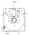
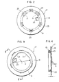
- Figs. 1 to 4 show a first application embodiment 1 of a disk cartridge according to the present invention, where Fig. 1 is a bottom plan view of a disk cartridge, Fig. 2 is a plan view of a hub, Fig. 3 is a bottom plan view of the hub, and Fig. 4 is a cross-sectional view along the line IV-IV of Fig. 3.
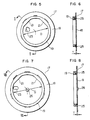
- FIGs. 5 and 6 show a second application embodiment of a hub according to the present invention, where Fig. 5 is a bottom plan view of a hub and Fig. 6 is a cross-sectional view along the line II-II of Fig. 5.
- Figs. 7 and 8 show a third application embodiment of a hub according to the present invention, where Fig. 7 is a bottom plan view of a hub and Fig. 7 is a cross-sectional view along the line VIII-VIII of Fig. 7.
- Fig. 9 shows a vertically cross-sectional front view of a hub and its neighbourhood structure according to the prior art.
- Figs. 1 to 4 show a first application embodiment of a disk cartridge.
- a disk cartridge (nominal size: 2.5 inch) is composed of a rectangular case 1 and a disk 2 rotatably encased therein.
- the case 1 is composed of upper and lower shells 3a and 3b joined together at the edges to form a hollow inside.
- the lower shell 3b has a circular driving shaft insert opening 4 substantially at the center thereof, and both upper and lower shells 3a and 3b each have a rectangular head insert 5 at the position near the front end.
- the head insert openings 5 are brought into an open or closed state by the shutter 6 .
- the shutter 6 is injection molded from a compound plastic containing a reinforcing filler, and supported slidably in the lateral direction of the case 1 , and kept by the force of a spring 7 at a position to close the head insert openings 5 when the disk cartridge is not charged into a disk drive, while the shutter 6 undergoes opening operation against the force of the spring 7 when charged into the disk drive.
- the lower shell 3b further has insert holes 8 for a positioning pin, an operational groove 10 for operating a write protect notch 9 , etc.
- the upper shell 3a has a detection hole 11 of the same shape as the operating groove 10 capable of being opened or closed by the write protect notch 9 and a recess for pasting a label.
- Cleaning members 13 capable of sandwiching the disk 2 through liner sheets not shown in the drawings are provided on the inside surfaces of the upper and lower shells 3a and 3b at a position on the disk-coming side in the disk rotating direction as viewed from the head insert opening 5 . These cleaning members 13 are supported from the outside of the case through operational openings 14 provided through the walls of the upper and lower shells 3a and 3b to make cleaning of the disk 2 and prevent the flapping of a magnetic sheet 16 as driven.
- the disk 2 is composed of a circular magnetic sheet 16 and a hub 17 facing the said driving shaft insert opening 4 as fixed at the center of the magnetic sheet 16 .
- the hub 17 is composed of a flange 18 made from a thin magnetic stainless steel sheet of SUS 430 and a control ring 19 as fixed thereto by outsert molding.
- the magnetic sheet 16 is fixed to a flange portion of the plate 18 by adhesion.
- the control ring 19 has a chevron-shaped positioning part 21 for concentrically positioning the entire disk with respect to the driving shaft of the disk drive, whereas the flange 18 has a diamond-shaped driving hole 23 with which a driving pin is engaged.
- connection lugs 25 are formed by blanking from the sheet of flange 18 toward the peripheral side and are embedded into the wall of the control ring 19 as shown in Figs. 2 and 4.
- the connecting lugs 25 are provided at 6 positions in the peripheral direction of the control ring 19 including the position corresponding to the positioning part 21 .
- the connection lug corresponding to the positioning part 21 is formed broader and longer than other connection lugs.
- the main dimensions of the hub 17 applied to the disk cartridge of 2.5-inch nominal size shown in Figs. 1 to 4 are as follows:
- hub 17 The main dimensions of hub 17 are as follows;
- Figs. 7 and 8 show a third application embodiment of other hub for a disk cartridge of 5-inch nominal size, where the hub 17 has basically the same structure as that for the disk cartridge disk of 2.5-inch nominal size as shown in Figs. 1 to 4, but there are small changes in the shape, that is, the shape of the driving hole 23 is changed to an oblong shape and a projection 26 for attrition reduction is provided at the center of the plate surface of flange 18 .
- hub 17 The main dimensions of hub 17 are as follows:
- Hubs 17 shown in Figs. 2 to 4 were outsert molded from compound plastics composed each of polybutylene terephthalate as a plastic base material and 0 to 30% by weight of potassium titanate in a whisker form as a filler, on the basis of the weight of the respective compound plastic, as shown in the following Table 1.
- the whiskers of potassium titanate had an average fiber length of 10 to 20 ⁇ m, a fiber diameter of 0.2 to 0.5 ⁇ m, a Mohs hardness of 4.0, a tensile strength of 500 to 700 kgf/mm2, a modulus in tension of about 28,000 kgf/mm2, and a volume resistivity of 3.3 x 10¹⁵ ⁇ cm.
- the flange 18 was made from a stainless steel sheet (3 mm-thick, SUS 430).
- Example 2 In the material No. 4 of Example 1, a hub 17 was outsert molded in the same manner as in Example 1, except that polybutylene terephthalate was replaced with polyacetal as the plastic base material. The thus obtained hub was identified as material No. 6. Another hub molded from the same compound plastic without the filler, that is, single polyacetal was identified as Comparative Example 2.
- Hubs 17 were outsert molded in the same manner as in Example 1, except that the whiskers of potassium titanate were replaced with talc, calcium carbonate, graphite or glass fibers as the filler in Example 2. They were identified as given in the following Table 2.
- the amounts of warping deformation ⁇ of the hubs 17 obtained by outsert molding the said materials Nos. 1 to 10 and Comparative Examples 1 to 2 were measured. As shown in Fig. 4, the amounts of warping deformation ⁇ were determined by measuring a difference in the thickness direction of the flange between the center of the plate 18 and the position of inner side edge of the control ring 19 by a dial gage.
- the heat resistance was determined by keeping the hubs at 60°C for 48 hours, leaving them at the ordinary temperature for 24 hours, and observing a change in the inner diameter of control ring 19 .
- Attrition resistance was determined by engaging a rotating shaft S with the hub 17 by 20,000 repetitions and visually observing the attrition state of the positioning part 21 .
- a double round mark "o” shows no substantial attrition; a round mark “O” shows a slight attrition; a triangular mark “ ⁇ ” shows a substantial attrition.
- the control ring 19 is outsert molded from a compound plastic containing a reinforcing filler capable of improving a molding shrinkage in the present invention, whereby the coefficient of thermal expansion of the control ring 19 can be made as near that of the material of constructions for the plate 18 as possible, and thus the warping deformation of the plate 18 can be lowered to a negligible degree during the mold solidification, attaining a higher plane precision and preventing a track deviation, etc. Furthermore, the mechanical strength and the attrition resistance can be increased by the reinforcing action of the filler, as is obvious from Table 3, and thus the control ring 19 can be given an improved durability and a smaller size with ease.
Landscapes
- Compositions Of Macromolecular Compounds (AREA)
- Optical Record Carriers And Manufacture Thereof (AREA)
Claims (6)
- Plattenkassette mit einem Gehäuse (1) und einer innerhalb des Gehäuses drehbaren Platte (2), die eine Nabe (17) mit einem Positionierring (19) zur konzentrischen Positionierung der Nabe (17) und Platte (16) in bezug auf die Antriebswelle eines Plattenantriebs und eine Metallplatte (18) mit einem Flanschteil aufweist, das sich vom Positionierring (19) radial nach außen erstreckt und durch Formung des Rings (19) aus einem Kunststoffmaterial damit integriert ist,
dadurch gekennzeichnet,
daß die Metallplatte (18) ferner ein im wesentlichen die Mitte des Positionierrings füllendes Innenteil hat, daß das Kunststoffmaterial ein Verbundkunststoff ist, der ein Kunststoff-Grundmaterial aufweist, das mit einem Füllmaterial derart gemischt ist, daß eine Verarbeitungsschrumpfung von nicht mehr als 1,8% während des Formens erreicht wird, und daß das Maßverhältnis von Plattendicke zu Innendurchmesser des Positionierrings im Bereich von 1/50 bis 1/30 liegt. - Plattenkassette nach Anspruch 1, bei der das Kunststoff-Grundmaterial für den Verbundkunststoff Polybutylen-Terephthalat ist.
- Plattenkassette nach Anspruch 1,
bei der das Kunststoff-Grundmaterial für den Verbundkunststoff ein Polyacetal ist. - Plattenkassette nach Anspruch 1, 2 oder 3,
bei der das Füllmaterial Kaliumtitanat ist. - Plattenkassette nach einem der vorhergehenden Ansprüche, bei der das Kunststoffmaterial 5 bis 40 Masse-% Füllmaterial enthält.
- Plattenkassette nach einem der vorhergehenden Ansprüche, bei der der Positionierring (19) ein Chevron-förmiges Positionierteil (21) zur konzentrischen Positionierung der Nabe (17) und Platte in bezug auf die Antriebswelle(n) eines Plattenantriebs aufweist.
Applications Claiming Priority (2)
| Application Number | Priority Date | Filing Date | Title |
|---|---|---|---|
| JP50878/86 | 1986-03-07 | ||
| JP61050878A JPS62208480A (ja) | 1986-03-07 | 1986-03-07 | デイスクカ−トリツジ |
Publications (2)
| Publication Number | Publication Date |
|---|---|
| EP0240170A1 EP0240170A1 (de) | 1987-10-07 |
| EP0240170B1 true EP0240170B1 (de) | 1991-07-10 |
Family
ID=12870980
Family Applications (1)
| Application Number | Title | Priority Date | Filing Date |
|---|---|---|---|
| EP87301857A Expired EP0240170B1 (de) | 1986-03-07 | 1987-03-03 | Plattenkassette |
Country Status (4)
| Country | Link |
|---|---|
| US (1) | US4885653A (de) |
| EP (1) | EP0240170B1 (de) |
| JP (1) | JPS62208480A (de) |
| DE (1) | DE3771246D1 (de) |
Families Citing this family (20)
| Publication number | Priority date | Publication date | Assignee | Title |
|---|---|---|---|---|
| JPS6437740A (en) * | 1987-07-31 | 1989-02-08 | Mitsui Petrochemical Ind | Manufacture of magnetic hub |
| US5010435A (en) * | 1987-12-03 | 1991-04-23 | Tdk Corporation | Hub for a disk type recording medium |
| EP0356811B1 (de) * | 1988-08-30 | 1994-11-02 | Mitsubishi Rayon Co., Ltd. | Nabe für optische Speicherplatte und Verfahren zu deren Herstellung |
| US5220543A (en) * | 1989-02-14 | 1993-06-15 | Victor Company Of Japan, Ltd. | Compact optical disc recording/reproducing system |
| JPH0316074A (ja) * | 1989-03-15 | 1991-01-24 | Tdk Corp | テープカセット用ハブ |
| JP2844877B2 (ja) * | 1990-08-09 | 1999-01-13 | 松下電器産業株式会社 | 回転ヘッドシリンダーおよびその製造方法 |
| JP3209434B2 (ja) * | 1991-01-31 | 2001-09-17 | ソニー株式会社 | ディスクカートリッジ |
| US5177656A (en) * | 1991-02-05 | 1993-01-05 | Hoechst Celanese Corporation | Flexible magnetic disc cassettes with integrally molded wear button |
| US5164871A (en) * | 1991-02-05 | 1992-11-17 | Hoechst Celanese Corporation | Shutters with integrally molded spring elements for flexible magnetic disc cassettes |
| US5200871A (en) * | 1991-02-05 | 1993-04-06 | Hoechst Celanese Corporation | Flexible magnetic disc cassettes with integrally molded drag fingers |
| US5212614A (en) * | 1991-02-05 | 1993-05-18 | Hoechst Celanese Corporation | Flexible magnetic disc cassettes with separable cassette cases |
| US5214555A (en) * | 1991-04-12 | 1993-05-25 | Hoechst Celanese Corporation | Central hubs for flexible magnetic data discs formed of magnetically soft polyacetal compositions |
| DE9109036U1 (de) * | 1991-07-23 | 1991-10-17 | BASF Magnetics GmbH, 6800 Mannheim | Aufzeichnungsplatte mit einem Gehäuse, insbesondere Magnetplatte mit einer Hülle |
| US5768253A (en) * | 1992-05-15 | 1998-06-16 | Cd Plant Tecval S.A. | Disc cartridge for accommodating recording discs |
| JPH064908A (ja) * | 1992-06-22 | 1994-01-14 | Awa Eng Co | 光ディスクとその製造装置 |
| JPH09270161A (ja) * | 1996-01-31 | 1997-10-14 | Mitsubishi Electric Corp | 記憶装置及び記録媒体カートリッジ |
| US5833777A (en) * | 1997-09-16 | 1998-11-10 | Intri-Plex Technologies, Inc. | Base plate for suspension assembly in a hard disk drive with a hardened flange and soft hub |
| USD422997S (en) * | 1997-11-20 | 2000-04-18 | Sony Corporation | Magnetic disc cartridge |
| GB0323982D0 (en) * | 2003-10-13 | 2003-11-19 | Microgen Energy Ltd | Improvements relating to the operation of an engine |
| US7448055B2 (en) * | 2004-05-28 | 2008-11-04 | Hitachi Global Storage Technologies Netherlands B.V. | Disk assembly having integral clamp and/or spacer |
Family Cites Families (16)
| Publication number | Priority date | Publication date | Assignee | Title |
|---|---|---|---|---|
| JPS5228131B2 (de) * | 1973-02-05 | 1977-07-25 | ||
| JPS579393B2 (de) * | 1974-06-13 | 1982-02-20 | ||
| JPS5136264A (ja) * | 1974-09-19 | 1976-03-27 | Mitsubishi Monsanto Chem | Garasusenikyokahoribuchirenterefutareetojushisoseibutsu |
| JPS6035944B2 (ja) * | 1977-03-01 | 1985-08-17 | 三菱化学株式会社 | ガラス繊維強化ポリエステル樹脂組成物 |
| US4366516A (en) * | 1979-05-29 | 1982-12-28 | Hitachi, Ltd. | Precision machinery component |
| US4429004A (en) * | 1980-06-26 | 1984-01-31 | Ciba-Geigy Corporation | Light-reflecting body |
| DE3271676D1 (en) * | 1981-10-30 | 1986-07-17 | Gen Electric | Reinforced thermoplastic composition |
| JPS5950034U (ja) * | 1982-09-21 | 1984-04-03 | ソニー株式会社 | 情報記録シ−ト |
| US4630156A (en) * | 1983-02-10 | 1986-12-16 | Sony Corporation | Flexible magnetic disc including hub structure |
| JPS59207050A (ja) * | 1983-05-10 | 1984-11-24 | Otsuka Chem Co Ltd | 映像録画テ−プガイド製造用樹脂組成物 |
| JPS6035385A (ja) * | 1983-08-03 | 1985-02-23 | Hitachi Maxell Ltd | デイスクカ−トリツジ |
| JPS6047279A (ja) * | 1983-08-24 | 1985-03-14 | Hitachi Maxell Ltd | デイスクカ−トリツジ |
| JPS60223852A (ja) * | 1984-04-19 | 1985-11-08 | Polyplastics Co | ポリアセタ−ル樹脂組成物 |
| JPS61131277A (ja) * | 1984-11-30 | 1986-06-18 | Hitachi Maxell Ltd | 記録デイスク |
| JPS61208684A (ja) * | 1985-03-13 | 1986-09-17 | Fujitsu Ltd | フレキシブル磁気ディスク |
| US4686666A (en) * | 1986-06-27 | 1987-08-11 | Dcteq | Flexible micro disk |
-
1986
- 1986-03-07 JP JP61050878A patent/JPS62208480A/ja active Pending
-
1987
- 1987-03-03 EP EP87301857A patent/EP0240170B1/de not_active Expired
- 1987-03-03 DE DE8787301857T patent/DE3771246D1/de not_active Expired - Lifetime
-
1989
- 1989-04-19 US US07/342,581 patent/US4885653A/en not_active Expired - Lifetime
Also Published As
| Publication number | Publication date |
|---|---|
| EP0240170A1 (de) | 1987-10-07 |
| JPS62208480A (ja) | 1987-09-12 |
| DE3771246D1 (de) | 1991-08-14 |
| US4885653A (en) | 1989-12-05 |
Similar Documents
| Publication | Publication Date | Title |
|---|---|---|
| EP0240170B1 (de) | Plattenkassette | |
| EP0236100B1 (de) | Plattenkassette | |
| US4698714A (en) | Flexible magnetic disc cassette | |
| EP0054640B1 (de) | Mehrschichtige magnetische Aufzeichnungsplatte | |
| US5585989A (en) | Magnetic disc substrate and a magnetic disc using the same | |
| EP0329425A2 (de) | Optisches Aufzeichnungsmedium und dessen Herstellungsverfahren | |
| US4757412A (en) | Disk cartridge | |
| JPH0465477B2 (de) | ||
| EP0965985A2 (de) | Informationsaufzeichnungsmedium | |
| JPH0782727B2 (ja) | 磁気ディスクカセット | |
| EP0448320B1 (de) | Verschluss für Kassette und Verfahren zum Giessen desselben | |
| EP0494794B1 (de) | Plattenkassette | |
| JP2747925B2 (ja) | 光メモリデイスクハブの形成方法 | |
| EP0390564B1 (de) | Metallform für ein Harz-Substrat für einen optischen Aufzeichnungsträger und Aufzeichnungsträger dadurch erhalten | |
| US6636476B1 (en) | Optical recording medium with a substrate of two different resin layers | |
| JP2709054B2 (ja) | デイスクカートリツジ | |
| US4760482A (en) | Outwardly tensioned magnetic disc cartridge | |
| US6212037B1 (en) | Disk cartridges | |
| JPH0240624Y2 (de) | ||
| JP2538206B2 (ja) | ディスクカ―トリッジ用ハブ並びにその製造方法 | |
| JPH05225742A (ja) | ディスクカートリッジ | |
| JP2754905B2 (ja) | 光磁気ディスクカセット用シャッタ | |
| JPH09180252A (ja) | 光記録媒体の基板およびその製造方法 | |
| JP2000021118A (ja) | 磁気ディスクカ―トリッジ | |
| KR20050025119A (ko) | 광학 기록 매체 |
Legal Events
| Date | Code | Title | Description |
|---|---|---|---|
| PUAI | Public reference made under article 153(3) epc to a published international application that has entered the european phase |
Free format text: ORIGINAL CODE: 0009012 |
|
| AK | Designated contracting states |
Kind code of ref document: A1 Designated state(s): DE GB |
|
| 17P | Request for examination filed |
Effective date: 19880229 |
|
| 17Q | First examination report despatched |
Effective date: 19890921 |
|
| GRAA | (expected) grant |
Free format text: ORIGINAL CODE: 0009210 |
|
| AK | Designated contracting states |
Kind code of ref document: B1 Designated state(s): DE GB |
|
| REF | Corresponds to: |
Ref document number: 3771246 Country of ref document: DE Date of ref document: 19910814 |
|
| PLBE | No opposition filed within time limit |
Free format text: ORIGINAL CODE: 0009261 |
|
| STAA | Information on the status of an ep patent application or granted ep patent |
Free format text: STATUS: NO OPPOSITION FILED WITHIN TIME LIMIT |
|
| 26N | No opposition filed | ||
| PGFP | Annual fee paid to national office [announced via postgrant information from national office to epo] |
Ref country code: GB Payment date: 20010228 Year of fee payment: 15 |
|
| PGFP | Annual fee paid to national office [announced via postgrant information from national office to epo] |
Ref country code: DE Payment date: 20010530 Year of fee payment: 15 |
|
| REG | Reference to a national code |
Ref country code: GB Ref legal event code: IF02 |
|
| PG25 | Lapsed in a contracting state [announced via postgrant information from national office to epo] |
Ref country code: GB Free format text: LAPSE BECAUSE OF NON-PAYMENT OF DUE FEES Effective date: 20020303 |
|
| PG25 | Lapsed in a contracting state [announced via postgrant information from national office to epo] |
Ref country code: DE Free format text: LAPSE BECAUSE OF NON-PAYMENT OF DUE FEES Effective date: 20021001 |
|
| GBPC | Gb: european patent ceased through non-payment of renewal fee |
Effective date: 20020303 |