EP0238944A2 - Montagegerät - Google Patents
Montagegerät Download PDFInfo
- Publication number
- EP0238944A2 EP0238944A2 EP87103591A EP87103591A EP0238944A2 EP 0238944 A2 EP0238944 A2 EP 0238944A2 EP 87103591 A EP87103591 A EP 87103591A EP 87103591 A EP87103591 A EP 87103591A EP 0238944 A2 EP0238944 A2 EP 0238944A2
- Authority
- EP
- European Patent Office
- Prior art keywords
- equipment according
- mounting part
- wall
- connection
- shaft
- Prior art date
- Legal status (The legal status is an assumption and is not a legal conclusion. Google has not performed a legal analysis and makes no representation as to the accuracy of the status listed.)
- Granted
Links
- 239000002184 metal Substances 0.000 claims description 2
- 238000011161 development Methods 0.000 description 1
- 230000018109 developmental process Effects 0.000 description 1
- 238000004804 winding Methods 0.000 description 1
Images
Classifications
-
- E—FIXED CONSTRUCTIONS
- E06—DOORS, WINDOWS, SHUTTERS, OR ROLLER BLINDS IN GENERAL; LADDERS
- E06B—FIXED OR MOVABLE CLOSURES FOR OPENINGS IN BUILDINGS, VEHICLES, FENCES OR LIKE ENCLOSURES IN GENERAL, e.g. DOORS, WINDOWS, BLINDS, GATES
- E06B9/00—Screening or protective devices for wall or similar openings, with or without operating or securing mechanisms; Closures of similar construction
- E06B9/56—Operating, guiding or securing devices or arrangements for roll-type closures; Spring drums; Tape drums; Counterweighting arrangements therefor
- E06B9/68—Operating devices or mechanisms, e.g. with electric drive
- E06B9/70—Operating devices or mechanisms, e.g. with electric drive comprising an electric motor positioned outside the roller
-
- E—FIXED CONSTRUCTIONS
- E06—DOORS, WINDOWS, SHUTTERS, OR ROLLER BLINDS IN GENERAL; LADDERS
- E06B—FIXED OR MOVABLE CLOSURES FOR OPENINGS IN BUILDINGS, VEHICLES, FENCES OR LIKE ENCLOSURES IN GENERAL, e.g. DOORS, WINDOWS, BLINDS, GATES
- E06B9/00—Screening or protective devices for wall or similar openings, with or without operating or securing mechanisms; Closures of similar construction
- E06B9/02—Shutters, movable grilles, or other safety closing devices, e.g. against burglary
- E06B9/08—Roll-type closures
- E06B9/11—Roller shutters
- E06B9/17—Parts or details of roller shutters, e.g. suspension devices, shutter boxes, wicket doors, ventilation openings
- E06B9/174—Bearings specially adapted therefor
-
- E—FIXED CONSTRUCTIONS
- E06—DOORS, WINDOWS, SHUTTERS, OR ROLLER BLINDS IN GENERAL; LADDERS
- E06B—FIXED OR MOVABLE CLOSURES FOR OPENINGS IN BUILDINGS, VEHICLES, FENCES OR LIKE ENCLOSURES IN GENERAL, e.g. DOORS, WINDOWS, BLINDS, GATES
- E06B9/00—Screening or protective devices for wall or similar openings, with or without operating or securing mechanisms; Closures of similar construction
- E06B9/56—Operating, guiding or securing devices or arrangements for roll-type closures; Spring drums; Tape drums; Counterweighting arrangements therefor
- E06B9/78—Operating, guiding or securing devices or arrangements for roll-type closures; Spring drums; Tape drums; Counterweighting arrangements therefor for direct manual operation, e.g. by tassels, by handles
Definitions
- the invention relates to an assembly device for lifting the preferably wound on a shaft armor of a roller shutter according to the preamble of the main claim.
- the assembly of the wound-up tank is also dangerous because it can fall off the relatively narrow tines of the truck.
- the invention has for its object to provide an assembly device according to the preamble of the main claim so that the assembly can be carried out easily and without a forklift and safely with a simultaneous load test of the wall brackets.
- the mounting part is fixed to the wall bracket, which is provided with a guide device for the rope of a hoist and protrudes so far over the wall bracket and protrudes upwards, so that the shaft projecting laterally over the armor is lifted past the wall bracket at the front can.
- the sufficient dimension serves to keep the shaft on inserted drive on one side and a shaft bearing on the other side at the same time on the wall bracket.
- the wound-up shaft When the wound-up shaft has reached its height, it is deflected from the projecting area into the horizontal by means of the guide device and pulled in the direction of the wall. The shaft can then be lowered at the assembly point, whereby the attached bearing bush or the drive comes to rest on the wall bracket.
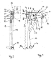
- the wall bracket 5 provided with fastening bores has a base plate 6 for abutment against the wall 7 and a cantilever arm 8 projecting forward and a support strut 9, which together enclose approximately a triangular space l0.
- the disc-shaped trained actual mounting part has a projection l2, which protrudes beyond the front end of the cantilever arm 8 so far that the armor of a roller shutter, which is denoted overall by l3 and is wound on a shaft l4, can be raised unhindered by means of a rope l5.
- holding parts l6 are attached to the lateral shaft ends, on which the rope is fixed.
- the mounting part 11 is connected to the cantilever arm 8 of the wall bracket 5 via two places, specifically via a first detachable screw connection l7 arranged near the wall 7 and a second connection, generally designated l8, which is designed as a two-armed lever (FIG. 2) , one end of which l9 engages in the groove 20 of the cantilever arm 8 by means of a T-shaped part and is fixed there by means of a clamp connection, which is generally designated 2l and is known per se.
- the other end of the double lever l8 is also releasably fixed by means of a clamping connection schematically designated at 22 to a support lever designated overall as 23 and reaching downwards, the lower end of which carries a motor with a winding drum 24 for the cable l5 and by means of a support plate 25 for the wall 7 is provided.
- the fulcrum of the double lever 18 is designed as a hinge 26, which is fixed to the mounting part 11.
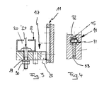
- the first screw connection 17 is shown in more detail in FIG. 3.
- the cantilever arm 8 has a profile which is double C-shaped in cross-section, into which the head of a hammer head screw, designated overall by 27, engages.
- the nut 30, which is supported by a washer 19 and is screwed onto this screw 27, rests against a transverse web, designated overall by 28, which is fixed to the actual mounting part 11. By loosening the nut 30, the mounting part 11 can be pivoted about the hinge 26 ( Figures 1 and 2).
- the mounting part 11 also has a guide device designated a total of 3l for the cable l5, which is provided with an endless roller chain 32 for guiding the cable of the hoist, the upper strand of which extends into the projecting region l2 of the motor part ll and is continuous in a vertical direction a horizontal direction is diverted. Furthermore, the horizontal area is at least up to the mounting position for the shaft bearing and the drive, which is located above the cantilever arm 8 of the wall bracket 5.
- the lower run of the roller chain can run freely or be tensioned using a chain tensioner.
- the roller chain 32 is guided on a sheet metal web designated 33 in total (FIG. 4).
Landscapes
- Engineering & Computer Science (AREA)
- Structural Engineering (AREA)
- Architecture (AREA)
- Civil Engineering (AREA)
- Operating, Guiding And Securing Of Roll- Type Closing Members (AREA)
- Perforating, Stamping-Out Or Severing By Means Other Than Cutting (AREA)
- Forklifts And Lifting Vehicles (AREA)
- Surgical Instruments (AREA)
- Types And Forms Of Lifts (AREA)
- Power-Operated Mechanisms For Wings (AREA)
- Telephone Function (AREA)
- Vehicle Body Suspensions (AREA)
- Supplying Of Containers To The Packaging Station (AREA)
- Spray Control Apparatus (AREA)
- Input Circuits Of Receivers And Coupling Of Receivers And Audio Equipment (AREA)
- Techniques For Improving Reliability Of Storages (AREA)
- Bidet-Like Cleaning Device And Other Flush Toilet Accessories (AREA)
Abstract
Description
- Die Erfindung betrifft eine Montagegerätschaft zum Anheben des vorzugsweise auf eine Welle aufgewickelten Panzers eines Rolltores gemäß dem Oberbegriff des Hauptanspruches.
- Solche Panzer sind bislang mittels eines Gabelstaplers angehoben und auf die Wandkonsolen abgelegt worden.
- Abgesehen davon, daß nicht nur ein Gabelstapler zur Montage notwendig ist, gestaltet sich die Montage des aufgewickelten Panzers auch gefährlich, weil dieser von dem relativ schmalen Zinken des Staplers herunterfallen kann. Außerdem ist nach der Montage nicht sichergestellt, ob der aufgewickelte Panzer von den Wandkonsolen getragen wird, wenn dieser von dem Gabelstapler losgelassen wird.
- Der Erfindung liegt die Aufgabe zugrunde, eine Montagegerätschaft gemäß dem Oberbegriff des Hauptanspruchs so auszubilden, daß die Montage einfach und ohne Gabelstapler sowie gefahrlos mit gleichzeitiger Belastungsprobe der Wandkonsolen durchgeführt werden kann.
- Diese Aufgabe wird bei einer Montagegerätschaft gemäß dem Oberbegriff des Hauptanspruchs erfindungsgemäß durch dessen kennzeichnende Merkmale gelöst.
- Hierbei wird an der Wandkonsole das Montageteil festgelegt, welches mit einer Führungseinrichtung für das Seil eines Hebezeugs versehen ist und soweit über die Wandkonsole nach vorne vorspringt und diese nach oben überragt, so daß die seitlich über den Panzer vorstehende Welle vorne an der Wandkonsole vorbei angehoben werden kann. Die ausreichend bemessene Höhe dient dazu, die Welle mit auf gestecktem Antrieb auf der einen Seite und einer Wellenlagerung auf der anderen Seite zugleich an der Wandkonsole festzulegen. Diese beiden Teile werden daher auf die Welle aufgesteckt und mit nach oben angehoben.
- Hat die aufgewickelte Welle ihre Höhe erreicht, so wird sie mittels der Führungseinrichtung von dem vorspringenden Bereich in die Waagerechte umgelenkt und in Richtung der Wand gezogen. An der Montagestelle kann die Welle dann abgesenkt werden, wobei die aufgesteckte Lagerbuchse bzw. der Antrieb auf der Wandkonsole zur Anlage kommt.
- Zweckmäßige Ausgestaltungen und Weiterbildungen der Erfindung sind in den Unteransprüchen gekennzeichnet.
- Ein bevorzugtes Ausführungsbeispiel der Erfindung wird nachfolgend unter Bezugnahme auf die Zeichnung näher erläutert. In dieser zeigt:
- Fig. l Die Wandkonsole und das Montageteil, in schematischer Seitenansicht;
- Fig. 2 die Wandkonsole gemäß Fig. l in Draufsicht;
- Fig. 3 einen Schnitt III-III gemäß Fig. l und
- Fig. 4 einen Schnitt IV-IV gemäß Fig. l.
- Die mit Befestigungsbohrungen versehene Wandkonsole 5 weist eine Grundplatte 6 zur Anlage an der Wand 7 sowie einen nach vorne vorspringenden Kragarm 8 sowie eine Stützstrebe 9 auf, die miteinander etwa eine dreieckförmigen Zwischenraum l0 einschließen.
- An dieser Wandkonsole 5 wird das insgesamt mit ll bezeichnete Montageteil angebracht. Das scheibenförmige ausgebildete eigentliche Montageteil weist einen Vorsprung l2 auf, der über das vordere Ende des Kragarms 8 so weit vorragt, daß der insgesamt mit l3 bezeichnete auf eine Welle l4 aufgewickelte Panzer eines Rolltores ungehindert mittels eines Seils l5 angehoben werden kann. Hierbei sind auf die seitlichen Wellenenden Halteteile l6 aufgesteckt, an denen das Seil festgelegt ist.
- Das Montageteil ll ist über zwei Stellen mit dem Kragarm 8 der Wandkonsole 5 verbunden, und zwar über ein nahe der Wand 7 angeordnete erste lösbare Schraubverbindung l7 und eine zweite, insgesamt mit l8 bezeichnete Verbindung, die als zweiarmiger Hebel (Fig. 2) ausgebildet ist, dessen eines Ende l9 mittels eines T-förmigen Teils in die Nut 20 des Kragarms 8 eingreift und dort mittels einer insgesamt mit 2l bezeichneten und an sich bekannten Klemmverbindung festgelegt ist. Das andere Ende des Doppelhebels l8 ist ebenfalls mittels einer mit 22 schematisch bezeichneten Klemmverbindung lösbar an einem insgesamt mit 23 bezeichneten und nach unten reichenden Stützhebel festgelegt, dessen unteres Ende einen Motor mit Aufwickeltrommel 24 für das Seil l5 trägt sowie mittels einer Abstützplatte 25 für die Wand 7 versehen ist. Der Drehpunkt des Doppelhebels l8 ist als Scharnier 26 ausgebildet, das an dem Montageteil ll festgelegt ist.
- Die erste Schraubverbindung l7 ist näher in Fig. 3 dargestellt. Der Kragarm 8 weist ein im Querschnitt doppelt C-förmiges Profil auf, in das der Kopf einer insgesamt mit 27 bezeichneten Hammerkopfschraube eingreift. Die über eine Unterlagscheibe l9 abgestützte Mutter 30, die auf diese Schraube 27 aufgeschraubt ist, liegt an einem insgesamt mit 28 bezeichneten Quersteg an, der an dem eigentlichen Montageteil ll festgelegt ist. Durch Lösen der Mutter 30 kann das Montageteil ll um das Scharnier 26 (Figuren l und 2) verschwenkt werden.
- Das Montageteil ll weist ferner für das Seil l5 eine insgesamt 3l bezeichnete Führungseinrichtung auf, die mit einer endlosen Rollenkette 32 zur Führung des Seils des Hebezeug versehen ist, deren Obertrum bis in den vorspringenden Bereich l2 des Motageteils ll reicht und von einer vertikalen Richtung stetig in eine horizontale Richtung umgelenkt wird. Ferner ist der horizontale Bereich wenigstens bis zu der Montagelage für das Wellenlager und den Antrieb geführt, die sich oberhalb des Kragarms 8 der Wandkonsole 5 befindet. Das Untertrum der Rollenkette kann frei laufen oder mittels eines Kettenspanners gespannt sein. Die Rollenkette 32 ist auf einen insgesamt mit 33 bezeichneten Blechsteg geführt (Fig.4).
Claims (16)
Priority Applications (1)
| Application Number | Priority Date | Filing Date | Title |
|---|---|---|---|
| AT87103591T ATE64173T1 (de) | 1986-03-27 | 1987-03-12 | Montagegeraet. |
Applications Claiming Priority (2)
| Application Number | Priority Date | Filing Date | Title |
|---|---|---|---|
| DE3610590 | 1986-03-27 | ||
| DE19863610590 DE3610590A1 (de) | 1986-03-27 | 1986-03-27 | Montagegeraetschaft |
Publications (3)
| Publication Number | Publication Date |
|---|---|
| EP0238944A2 true EP0238944A2 (de) | 1987-09-30 |
| EP0238944A3 EP0238944A3 (en) | 1988-03-02 |
| EP0238944B1 EP0238944B1 (de) | 1991-06-05 |
Family
ID=6297498
Family Applications (1)
| Application Number | Title | Priority Date | Filing Date |
|---|---|---|---|
| EP87103591A Expired - Lifetime EP0238944B1 (de) | 1986-03-27 | 1987-03-12 | Montagegerät |
Country Status (4)
| Country | Link |
|---|---|
| EP (1) | EP0238944B1 (de) |
| AT (1) | ATE64173T1 (de) |
| DE (2) | DE3610590A1 (de) |
| DK (1) | DK168232B1 (de) |
Cited By (4)
| Publication number | Priority date | Publication date | Assignee | Title |
|---|---|---|---|---|
| FR2819543A1 (fr) | 2001-01-12 | 2002-07-19 | Hormann Kg Dissen | Dispositif et procede de montage pour soulever le blindage d'une porte roulante |
| GB2403206A (en) * | 2003-05-31 | 2004-12-29 | Rsl Bristol Ltd | Roller shutter installation aid |
| EP1908915A2 (de) | 2006-09-28 | 2008-04-09 | Hörmann KG Dissen | Montageverfahren für Rolltor |
| DE102010031733A1 (de) | 2010-07-21 | 2012-01-26 | Hörmann KG Antriebstechnik | Montageverfahren und Montagehilfsgerät für ein Rolltor |
Families Citing this family (1)
| Publication number | Priority date | Publication date | Assignee | Title |
|---|---|---|---|---|
| DE10127015A1 (de) * | 2001-01-12 | 2002-07-18 | Hoermann Kg Dissen | Montagevorrichtung zum Anheben eines Panzers eines Rolltors sowie Verwendung derselben |
Family Cites Families (2)
| Publication number | Priority date | Publication date | Assignee | Title |
|---|---|---|---|---|
| US3672492A (en) * | 1971-02-09 | 1972-06-27 | North American Door Corp | Factory-assembled overhead door |
| FR2550270B1 (fr) * | 1983-08-05 | 1988-06-03 | Accoplas Fermetures | Dispositif pour le montage et le reglage de l'arbre d'enroulement d'un volet roulant |
-
1986
- 1986-03-27 DE DE19863610590 patent/DE3610590A1/de active Granted
-
1987
- 1987-03-12 EP EP87103591A patent/EP0238944B1/de not_active Expired - Lifetime
- 1987-03-12 AT AT87103591T patent/ATE64173T1/de not_active IP Right Cessation
- 1987-03-12 DE DE8787103591T patent/DE3770502D1/de not_active Expired - Fee Related
- 1987-03-26 DK DK153287A patent/DK168232B1/da not_active IP Right Cessation
Cited By (7)
| Publication number | Priority date | Publication date | Assignee | Title |
|---|---|---|---|---|
| FR2819543A1 (fr) | 2001-01-12 | 2002-07-19 | Hormann Kg Dissen | Dispositif et procede de montage pour soulever le blindage d'une porte roulante |
| GB2403206A (en) * | 2003-05-31 | 2004-12-29 | Rsl Bristol Ltd | Roller shutter installation aid |
| GB2403206B (en) * | 2003-05-31 | 2006-06-28 | Rsl Bristol Ltd | Roller shutter assembly installation |
| EP1908915A2 (de) | 2006-09-28 | 2008-04-09 | Hörmann KG Dissen | Montageverfahren für Rolltor |
| DE102006046008B3 (de) * | 2006-09-28 | 2008-04-30 | Hörmann Kg Dissen | Montageverfahren für Rolltor und ein solches Rolltor |
| DE102010031733A1 (de) | 2010-07-21 | 2012-01-26 | Hörmann KG Antriebstechnik | Montageverfahren und Montagehilfsgerät für ein Rolltor |
| WO2012022567A1 (de) | 2010-07-21 | 2012-02-23 | Hörmann KG Antriebstechnik | Montageverfahren und montagehilfsvorrichtung für ein rolltor |
Also Published As
| Publication number | Publication date |
|---|---|
| DK153287D0 (da) | 1987-03-26 |
| DK168232B1 (da) | 1994-02-28 |
| DE3610590C2 (de) | 1989-05-03 |
| EP0238944B1 (de) | 1991-06-05 |
| DE3770502D1 (de) | 1991-07-11 |
| EP0238944A3 (en) | 1988-03-02 |
| ATE64173T1 (de) | 1991-06-15 |
| DE3610590A1 (de) | 1987-10-01 |
| DK153287A (da) | 1987-09-28 |
Similar Documents
| Publication | Publication Date | Title |
|---|---|---|
| EP0501140A1 (de) | In einem Aufzugsschacht verfahrbares Montagegerüst zur Montage von Schachtausrüstung | |
| EP0238944B1 (de) | Montagegerät | |
| DE3536554A1 (de) | Schiebetor | |
| DE19812959A1 (de) | Hubvorrichtung, insbesondere zum Einbau in Möbeln | |
| DE3104537C2 (de) | "Vorrichtung zum Verstauen und Lagern von Surfbrettern in Garagen" | |
| DE2650697C3 (de) | Abschleppkran für Kraftfahrzeuge | |
| EP0105504A1 (de) | Verfahren und Vorrichtung zum Demontieren von Deckenschalungen | |
| DE8608523U1 (de) | Montagegerätschaft | |
| DE2406330A1 (de) | Vorrichtung zum ein- und ausbau des antriebsaggregates von kettenfahrzeugen | |
| DE2602745A1 (de) | Hebevorrichtung zum heben und aufrichten langgestreckter koerper | |
| DE7339749U (de) | Vorrichtung zum Einführen von gebündelten Kabeln in Kabelverlegemaschinen | |
| DE3422976A1 (de) | Stapelstaender | |
| DE3801057A1 (de) | Transportvorrichtung fuer eine haengefoerdervorrichtung | |
| DE933679C (de) | Vorrichtung, die dem Verkehr mit dem Schiff dient | |
| DE2134629A1 (de) | Tragbare motorsaege | |
| DE9406439U1 (de) | Vorrichtung zum selbsttätigen Anheben zum Aufhängen eines Elektrokettenzuges | |
| AT403675B (de) | Hebevorrichtung an einem holzspaltgerät | |
| DE8136572U1 (de) | Vorrichtung zum umscheren des hubseils bei kranen | |
| DE1242349B (de) | Vorrichtung zum Einbauen unverglaster Fensterrahmen in Gebaeuden | |
| DE3532066A1 (de) | Turmdrehkran | |
| DE29711884U1 (de) | Träger und Vorrichtung zum Einbau eines Trägers | |
| DE1556706C3 (de) | Schrapper | |
| DE658428C (de) | Schutzvorrichtung an Schiffsluken gegen Sturz in den Laderaum | |
| DE3015338A1 (de) | Vorrichtung zum handhaben von containern | |
| DE3915501A1 (de) | Transportable baueinheit mit einer seilwinde zum ziehen einer last |
Legal Events
| Date | Code | Title | Description |
|---|---|---|---|
| PUAI | Public reference made under article 153(3) epc to a published international application that has entered the european phase |
Free format text: ORIGINAL CODE: 0009012 |
|
| AK | Designated contracting states |
Kind code of ref document: A2 Designated state(s): AT BE CH DE ES FR GB GR IT LI LU NL SE |
|
| RBV | Designated contracting states (corrected) |
Designated state(s): AT BE CH DE FR GB IT LI NL SE |
|
| PUAL | Search report despatched |
Free format text: ORIGINAL CODE: 0009013 |
|
| AK | Designated contracting states |
Kind code of ref document: A3 Designated state(s): AT BE CH DE FR GB IT LI NL SE |
|
| 17P | Request for examination filed |
Effective date: 19880518 |
|
| 17Q | First examination report despatched |
Effective date: 19890227 |
|
| GRAA | (expected) grant |
Free format text: ORIGINAL CODE: 0009210 |
|
| AK | Designated contracting states |
Kind code of ref document: B1 Designated state(s): AT BE CH DE FR GB IT LI NL SE |
|
| REF | Corresponds to: |
Ref document number: 64173 Country of ref document: AT Date of ref document: 19910615 Kind code of ref document: T |
|
| REF | Corresponds to: |
Ref document number: 3770502 Country of ref document: DE Date of ref document: 19910711 |
|
| ET | Fr: translation filed | ||
| ITF | It: translation for a ep patent filed | ||
| GBT | Gb: translation of ep patent filed (gb section 77(6)(a)/1977) | ||
| PLBE | No opposition filed within time limit |
Free format text: ORIGINAL CODE: 0009261 |
|
| STAA | Information on the status of an ep patent application or granted ep patent |
Free format text: STATUS: NO OPPOSITION FILED WITHIN TIME LIMIT |
|
| 26N | No opposition filed | ||
| EAL | Se: european patent in force in sweden |
Ref document number: 87103591.1 |
|
| PGFP | Annual fee paid to national office [announced via postgrant information from national office to epo] |
Ref country code: SE Payment date: 20000307 Year of fee payment: 14 |
|
| PGFP | Annual fee paid to national office [announced via postgrant information from national office to epo] |
Ref country code: BE Payment date: 20000331 Year of fee payment: 14 |
|
| PG25 | Lapsed in a contracting state [announced via postgrant information from national office to epo] |
Ref country code: SE Free format text: LAPSE BECAUSE OF NON-PAYMENT OF DUE FEES Effective date: 20010313 |
|
| PGFP | Annual fee paid to national office [announced via postgrant information from national office to epo] |
Ref country code: AT Payment date: 20010314 Year of fee payment: 15 |
|
| PGFP | Annual fee paid to national office [announced via postgrant information from national office to epo] |
Ref country code: NL Payment date: 20010330 Year of fee payment: 15 |
|
| PG25 | Lapsed in a contracting state [announced via postgrant information from national office to epo] |
Ref country code: BE Free format text: LAPSE BECAUSE OF NON-PAYMENT OF DUE FEES Effective date: 20010331 |
|
| BERE | Be: lapsed |
Owner name: HORMANN K.G. BIELEFELD Effective date: 20010331 |
|
| EUG | Se: european patent has lapsed |
Ref document number: 87103591.1 |
|
| REG | Reference to a national code |
Ref country code: GB Ref legal event code: IF02 |
|
| PG25 | Lapsed in a contracting state [announced via postgrant information from national office to epo] |
Ref country code: AT Free format text: LAPSE BECAUSE OF NON-PAYMENT OF DUE FEES Effective date: 20020312 |
|
| PG25 | Lapsed in a contracting state [announced via postgrant information from national office to epo] |
Ref country code: NL Free format text: LAPSE BECAUSE OF NON-PAYMENT OF DUE FEES Effective date: 20021001 |
|
| NLV4 | Nl: lapsed or anulled due to non-payment of the annual fee |
Effective date: 20021001 |
|
| PGFP | Annual fee paid to national office [announced via postgrant information from national office to epo] |
Ref country code: GB Payment date: 20030305 Year of fee payment: 17 |
|
| PG25 | Lapsed in a contracting state [announced via postgrant information from national office to epo] |
Ref country code: GB Free format text: LAPSE BECAUSE OF NON-PAYMENT OF DUE FEES Effective date: 20040312 |
|
| PGFP | Annual fee paid to national office [announced via postgrant information from national office to epo] |
Ref country code: CH Payment date: 20040315 Year of fee payment: 18 |
|
| PGFP | Annual fee paid to national office [announced via postgrant information from national office to epo] |
Ref country code: DE Payment date: 20040329 Year of fee payment: 18 |
|
| PGFP | Annual fee paid to national office [announced via postgrant information from national office to epo] |
Ref country code: FR Payment date: 20040330 Year of fee payment: 18 |
|
| GBPC | Gb: european patent ceased through non-payment of renewal fee |
Effective date: 20040312 |
|
| PG25 | Lapsed in a contracting state [announced via postgrant information from national office to epo] |
Ref country code: IT Free format text: LAPSE BECAUSE OF NON-PAYMENT OF DUE FEES;WARNING: LAPSES OF ITALIAN PATENTS WITH EFFECTIVE DATE BEFORE 2007 MAY HAVE OCCURRED AT ANY TIME BEFORE 2007. THE CORRECT EFFECTIVE DATE MAY BE DIFFERENT FROM THE ONE RECORDED. Effective date: 20050312 |
|
| PG25 | Lapsed in a contracting state [announced via postgrant information from national office to epo] |
Ref country code: LI Free format text: LAPSE BECAUSE OF NON-PAYMENT OF DUE FEES Effective date: 20050331 Ref country code: CH Free format text: LAPSE BECAUSE OF NON-PAYMENT OF DUE FEES Effective date: 20050331 |
|
| PG25 | Lapsed in a contracting state [announced via postgrant information from national office to epo] |
Ref country code: DE Free format text: LAPSE BECAUSE OF NON-PAYMENT OF DUE FEES Effective date: 20051001 |
|
| REG | Reference to a national code |
Ref country code: CH Ref legal event code: PL |
|
| PG25 | Lapsed in a contracting state [announced via postgrant information from national office to epo] |
Ref country code: FR Free format text: LAPSE BECAUSE OF NON-PAYMENT OF DUE FEES Effective date: 20051130 |
|
| REG | Reference to a national code |
Ref country code: FR Ref legal event code: ST Effective date: 20051130 |