EP0237478B1 - Abdichtung einer Giessdüse gegen den Giessraum einer Stranggiessvorrichtung mit mindestens einem umlaufenden, flexiblen Kokillenband - Google Patents
Abdichtung einer Giessdüse gegen den Giessraum einer Stranggiessvorrichtung mit mindestens einem umlaufenden, flexiblen Kokillenband Download PDFInfo
- Publication number
- EP0237478B1 EP0237478B1 EP87810106A EP87810106A EP0237478B1 EP 0237478 B1 EP0237478 B1 EP 0237478B1 EP 87810106 A EP87810106 A EP 87810106A EP 87810106 A EP87810106 A EP 87810106A EP 0237478 B1 EP0237478 B1 EP 0237478B1
- Authority
- EP
- European Patent Office
- Prior art keywords
- nozzle
- belt
- sealing means
- casting
- means according
- Prior art date
- Legal status (The legal status is an assumption and is not a legal conclusion. Google has not performed a legal analysis and makes no representation as to the accuracy of the status listed.)
- Expired
Links
- 238000005266 casting Methods 0.000 title claims abstract description 51
- 238000007789 sealing Methods 0.000 title claims abstract description 24
- 238000009749 continuous casting Methods 0.000 title claims description 6
- 238000001816 cooling Methods 0.000 claims description 9
- 239000000110 cooling liquid Substances 0.000 claims description 6
- 229920002994 synthetic fiber Polymers 0.000 claims 1
- 239000002826 coolant Substances 0.000 abstract description 10
- 238000000034 method Methods 0.000 abstract description 6
- 238000003825 pressing Methods 0.000 abstract description 5
- 230000000694 effects Effects 0.000 abstract description 4
- 230000002706 hydrostatic effect Effects 0.000 abstract description 2
- 239000011248 coating agent Substances 0.000 abstract 1
- 238000000576 coating method Methods 0.000 abstract 1
- 239000000155 melt Substances 0.000 description 12
- 239000000463 material Substances 0.000 description 11
- 239000007788 liquid Substances 0.000 description 8
- 229910052751 metal Inorganic materials 0.000 description 5
- 239000002184 metal Substances 0.000 description 5
- 239000000243 solution Substances 0.000 description 5
- 239000000919 ceramic Substances 0.000 description 3
- 238000007711 solidification Methods 0.000 description 3
- 230000008023 solidification Effects 0.000 description 3
- 241001295925 Gegenes Species 0.000 description 2
- 229910052782 aluminium Inorganic materials 0.000 description 2
- XAGFODPZIPBFFR-UHFFFAOYSA-N aluminium Chemical compound [Al] XAGFODPZIPBFFR-UHFFFAOYSA-N 0.000 description 2
- TWNQGVIAIRXVLR-UHFFFAOYSA-N oxo(oxoalumanyloxy)alumane Chemical compound O=[Al]O[Al]=O TWNQGVIAIRXVLR-UHFFFAOYSA-N 0.000 description 2
- 230000001105 regulatory effect Effects 0.000 description 2
- 229910000505 Al2TiO5 Inorganic materials 0.000 description 1
- OKTJSMMVPCPJKN-UHFFFAOYSA-N Carbon Chemical compound [C] OKTJSMMVPCPJKN-UHFFFAOYSA-N 0.000 description 1
- 229910052581 Si3N4 Inorganic materials 0.000 description 1
- 229910000831 Steel Inorganic materials 0.000 description 1
- 239000011230 binding agent Substances 0.000 description 1
- -1 bomitride Substances 0.000 description 1
- 229910010293 ceramic material Inorganic materials 0.000 description 1
- 238000006243 chemical reaction Methods 0.000 description 1
- 230000002301 combined effect Effects 0.000 description 1
- 239000000498 cooling water Substances 0.000 description 1
- 230000003247 decreasing effect Effects 0.000 description 1
- 230000003628 erosive effect Effects 0.000 description 1
- 239000000835 fiber Substances 0.000 description 1
- 239000000945 filler Substances 0.000 description 1
- 229910002804 graphite Inorganic materials 0.000 description 1
- 239000010439 graphite Substances 0.000 description 1
- 229910001338 liquidmetal Inorganic materials 0.000 description 1
- 150000001247 metal acetylides Chemical class 0.000 description 1
- 238000013021 overheating Methods 0.000 description 1
- 230000036961 partial effect Effects 0.000 description 1
- 239000004033 plastic Substances 0.000 description 1
- 230000002028 premature Effects 0.000 description 1
- AABBHSMFGKYLKE-SNAWJCMRSA-N propan-2-yl (e)-but-2-enoate Chemical compound C\C=C\C(=O)OC(C)C AABBHSMFGKYLKE-SNAWJCMRSA-N 0.000 description 1
- 239000010453 quartz Substances 0.000 description 1
- 230000000284 resting effect Effects 0.000 description 1
- 238000007493 shaping process Methods 0.000 description 1
- 230000035939 shock Effects 0.000 description 1
- HBMJWWWQQXIZIP-UHFFFAOYSA-N silicon carbide Chemical compound [Si+]#[C-] HBMJWWWQQXIZIP-UHFFFAOYSA-N 0.000 description 1
- 229910010271 silicon carbide Inorganic materials 0.000 description 1
- VYPSYNLAJGMNEJ-UHFFFAOYSA-N silicon dioxide Inorganic materials O=[Si]=O VYPSYNLAJGMNEJ-UHFFFAOYSA-N 0.000 description 1
- HQVNEWCFYHHQES-UHFFFAOYSA-N silicon nitride Chemical compound N12[Si]34N5[Si]62N3[Si]51N64 HQVNEWCFYHHQES-UHFFFAOYSA-N 0.000 description 1
- 239000007921 spray Substances 0.000 description 1
- 238000005507 spraying Methods 0.000 description 1
- 230000003068 static effect Effects 0.000 description 1
- 239000010959 steel Substances 0.000 description 1
- 230000037303 wrinkles Effects 0.000 description 1
Images


Classifications
-
- B—PERFORMING OPERATIONS; TRANSPORTING
- B22—CASTING; POWDER METALLURGY
- B22D—CASTING OF METALS; CASTING OF OTHER SUBSTANCES BY THE SAME PROCESSES OR DEVICES
- B22D11/00—Continuous casting of metals, i.e. casting in indefinite lengths
- B22D11/06—Continuous casting of metals, i.e. casting in indefinite lengths into moulds with travelling walls, e.g. with rolls, plates, belts, caterpillars
- B22D11/0637—Accessories therefor
- B22D11/064—Accessories therefor for supplying molten metal
- B22D11/0645—Sealing means for the nozzle between the travelling surfaces
Definitions
- the present invention relates to a sealing of a casting nozzle against the casting space of a continuous casting device according to the preamble of claim 1.
- a known continuous casting device of this type is characterized by a so-called casting wheel, which is provided with a wheel rim internally cooled by means of a liquid (US Pat. No. 3,429,363).
- This has a depression corresponding to the desired strand dimension to be cast over the circumference and forms three sides of the casting space with the edges of the depression on both sides.
- the fourth side is now formed by a metal band resting on the edges and partially wrapping around the wheel rim, hereinafter referred to as the mold band, which creates a closed casting space over the circumference of the strand cross section to be cast.
- the mold belt is usually endless and is guided and tensioned over deflection rollers in order to form a casting mold of the desired length for a given wheel diameter.
- the mold belt is intensively cooled on the outside over the entire length of the casting space by means of an aqueous liquid. If the casting wheel is rotated by a drive, the mold belt runs along, creating a mold running with the cast material.
- a similar continuous casting device with casting wheel is also known from FR-A 1 418 754.
- the mold belt is covered with rigid plates which rest on the two edges of the casting wheel in the area of the casting wheel and thus do not exert any defined pressure on the casting nozzle which grips between the casting wheel and the mold belt.
- a further known continuous casting device is characterized in that the casting space is formed by two circumferential mold belts which are opposite one another at a certain distance and so-called side dams arranged on both sides between them (US Pat. No. 2,904,860 or 3,036,348).
- Circulating, endless mold belts are usually provided, which are guided and tensioned over appropriate deflection rollers. If a casting operation with interruptions is permissible, mold strips unwinding from a bundle can also be used, which are wound again after passing through the casting section or fed to the further processing as a cover layer combined with the casting material (DE Patent No. 1 508 876).
- the heat given off by the cast material to the mold belt is dissipated by means of intensive cooling through an aqueous liquid on the back of the mold belt.
- the melt is fed into the casting chamber by means of a feed device in the direction of the mold movement, where solidification takes place as a result of the heat removal, after which, depending on the casting material, a completely or partially solidified strand emerges from the casting room.
- So-called open or closed feed systems are used. In the open system, the melt flows through a suitable trough into the casting chamber, the inflow of the melt being regulated in a known manner. If high demands are placed on the quality of the cast strand, only a closed feed system can be used.
- a so-called pouring nozzle is used to feed the melt into the casting chamber, which protrudes into the casting chamber and closes it backwards.
- the material of the pouring nozzle is adapted to the properties of the molten metal.
- the material used for this must meet the requirements in terms of temperature, thermal shock on first contact with the melt, heat conduction, erosion, chemical reaction with the melt, machinability and economy.
- ceramic materials are in the foreground, depending on the existing requirements of various types. For example, pouring nozzles made of ceramic fibers based on Si 0 2 and A1 2 0 3 impregnated, compressed and fired with binder and filler, aluminum titanate, graphite, bomitride, quartz are used.
- the gap width is usually on the order of 0.1 to 0.5 mm.
- the metallostatic pressure of the melt at the outlet of the nozzle must be regulated within narrow limits. With increasing pressure and / or decreasing viscosity or surface tension of the melt, the sealing becomes more and more important. It is now known to create an increased sealing effect by suitable shaping of the nozzle. Even with the measures described, however, the risk of flowing backwards and the associated consequences remains.
- the aim of the present invention is now, in the case of casting devices of the two types described at the outset, to create a perfect seal of the casting space across its width between the mold belt and the casting nozzle. This goal is achieved by the measures according to the characterizing part of claim 1.
- the contact pressure is therefore dimensioned such that the metallostatic pressure of the melt at the outlet of the nozzle cannot lift the mold belt from the latter.
- the height difference corresponds to the difference between the level height in the tundish and the height of the lower mold surface at the nozzle outlet.
- the bar advantageously extends over the entire casting width of the nozzle.
- the bar can be in one piece or divided into several individual parts of any length. Plastic, metal or ceramic can be used as the material.
- the bar preferably has a width of 8 to 12 mm and a height of the same order of magnitude.
- Fig. 3 shows a vertical arrangement of the casting device.
- Another possibility is to bypass the pistons and allow the pressure medium to act directly on the strip 14 with appropriate sealing.
- springs 15 (FIG. 1) or pistons 16 (FIG. 3) are used, these are provided at a suitable distance a (FIG. 2) and are dimensioned such that the mold belt does not deviate from the metallostatic pressure at the outlet of the nozzle Nozzle is lifted off.
- FIG. 4 shows this solution in a vertical orientation.
- a force component acts on the mold belt.
- the leakage of the coolant backwards can be kept within permissible limits by means of a labyrinth seal 22, wherein the leakage liquid can be collected in the housing of the device and returned to the coolant system.
- the liquid stream 20 emerging from the coolant nozzle at a high speed covers the gan with a corresponding cooling effect ze back surface of the mold belt.
- FIG. 5 An additional variant according to FIG. 5 is that the static liquid pressure prevailing in the chamber 18 acts on the mold belt and presses it against the casting nozzle.
- the coolant on the belt 13 flows directly from the pressurized chamber 18 through the subsequent coolant nozzle 19. Since the kinetic energy of the liquid flow is exhausted some distance after the nozzle exit, the coolant can be replaced in a known manner at regular intervals.
- the mold strips can also be pressed in that the mold strip is guided in such a way that it runs in a diverging direction in front of the mouth of the pouring nozzle with respect to the center line thereof and is deflected in the pouring nozzle on the pouring nozzle, as a result of the tension of the Mold belt is generated a force acting on the nozzle.
- 6 illustrates a solution of this type in that both opposing mold belts 13 are directed via guides 22, the distance a of which is less than the height h of the pouring nozzle. This results in a diverging direction of the mold strip 13 with respect to the center line C-C of the pouring nozzle 11. As a result of the tension in the circumferential direction thereof, a force F directed against the pouring nozzle results.
- rollers can also be provided.
- A is the cross section of a mold belt, a is the tensile stress in it and ⁇ is the deflection angle on the casting nozzle, then:
- the contact pressure can be adapted to the metallostatic pressure prevailing at the outlet of the nozzle in all of the solutions described above.
- cooling can also be done by spraying from nozzles arranged at short intervals or using so-called support heads, e.g. according to EP-A 0 148 384. Since a certain friction arises between the pouring nozzle and a mold belt using the present invention, it is advantageous to apply a wear-resistant layer to the friction point of the nozzle. This can be done by known methods using the flame or plasma spray technique by adding a 0.1 to 0.2 mm thick layer, e.g. made of aluminum oxide.
- the mouthpiece of the nozzle 11 is provided with inserted wear plates 12.
- Materials such as aluminum oxide, silicon carbide or nitride, metal carbides, etc. are suitable for this.
- One of the measures mentioned can prevent premature wear of the pouring nozzle.
- the Swiss patent no. 508 433 describes a pouring nozzle with inlays made of a self-lubricating material attached near the mouth.
- the inserts serve the purpose of guiding the mouthpiece between the rigid mold halves of a caterpillar mold in such a way that the nozzle surface does not come into contact with the mold, even claiming that the inserts protrude from the surface of the nozzle in order to provide a direct To prevent contact of the nozzle surface with the mold by providing a gap of 0.2 to 0.3 mm between the nozzle and the mold surface.
- a sealing effect can only be achieved with a low metallostatic pressure of at most 20 to 30 mm liquid aluminum column.
- the present invention essentially differs from the type and mode of operation in question, firstly, that the inlays do not protrude from the nozzle surface, secondly, that the inlays are as close as possible to the nozzle outlet, and thirdly, that the inlays are made of a hard, wear-resistant material, to increase the operating time of the nozzle under the condition that the mold belts are pressed against it, and to create an integrity seal between the nozzle and the mold belt at all metallostatic pressures in the casting chamber that occur practically even when pouring in increasing direction.
- the pressing and sealing device allows, in contrast to the usual known systems, the cooling of the mold belts only after the pressing or sealing point, directly at the mouth of the pouring nozzle 11, i.e. still in the area of the pouring nozzle between the pressing point and the mouth , can take place.
- the cooling starts directly at the mouth of the pouring nozzle 11.
- the orientation of the pouring device or the pouring process is arbitrary. Instead of horizontal or vertical, as shown, it could also be inclined or directed upwards.
- the seal according to the invention has the advantage in any case that it is possible to work with higher metallostatic pressures when the melt supply system is closed, be it that a relatively high pressure results as a result of the vertical arrangement, or that the level in the horizontal or upward pouring direction Tundish is higher than usual.
- the vertical arrangement also offers advantages with regard to symmetrical cooling and generally symmetrical conditions during the casting and solidification process. The higher casting pressure leads to a safe reflow of the melt in the solidification area and thus to a high-quality structure of the cast strip.
Landscapes
- Engineering & Computer Science (AREA)
- Mechanical Engineering (AREA)
- Continuous Casting (AREA)
- Casting Or Compression Moulding Of Plastics Or The Like (AREA)
- Pressure Vessels And Lids Thereof (AREA)
Description
- Die vorliegende Erfindung betrifft eine Abdichtung einer Giessdüse gegen den Giessraum einer Stranggiessvorrichtung gemäss Oberbegriff des Anspruchs 1.
- Eine bekannte Stranggiessvorrichtung dieser Art ist gekennzeichnet durch ein sogenanntes Giessrad, welches mit einem mittels einer Flüssgkeit intern gekühlten Radkranz versehen ist (US-PS 3 429 363). Dieser weist über den Umfang eine der gewünschten, zu giessenden Strangdimension entsprechende Vertiefung auf und bildet mit den beidseitigen Rändern der Vertiefung drei Seiten des Giessraumes. Die vierte Seite wird nun durch ein auf den Rändern aufliegendes und den Radkranz teilweise umschlingendes Metallband gebildet, nachstehend Kokillenband genannt, womit ein über den Umfang des zu giessenden Strangquerschnittes geschlossener Giessraum entsteht. Das Kokillenband ist üblicherweise endlos und wird über Umlenkrollen geführt und gespannt, um bei gegebenem Raddurchmesser eine Giessform der gewünschten Länge zu bilden. Das Kokillenband wird auf dessen Aussenseite über die ganze Länge des Giessraumes intensiv mittels einer wässerigen Flüssigkeit gekühlt. Wird das Giessrad durch einen Antrieb in Drehung versetzt, so läuft das Kokillenband mit, wodurch eine mit dem Giessgut laufende Kokille geschaffen ist.
- Eine ähnliche Stranggiessvorrichtung mit Giessrad ist auch aus der FR-A 1 418 754 bekannt. Das Kokillenband ist hierbei mit starren Platten besetzt, welche im Bereiche des Giessrades auf die beiden Ränder desselben aufliegen und somit keinen definierten Druck auf die zwischen das Giessrad und das Kokillenband greifende Giessdüse ausüben.
- Eine weitere bekannte Stranggiessvorrichtung ist dadurch gekennzeichnet, dass der Giessraum durch zwei in bestimmtem Abstand einander gegenüberliegende, umlaufende Kokillenbänder und beidseitig zwischen diesen angeordnet sogenannte Seitendämme gebildet wird (US-PS 2 904 860 oder 3 036 348).
- Üblicherweise werden umlaufende, endlose Kokillenbänder vorgesehen, welche über zwecksentsprechende Umlenkrollen geführt und gespannt werden. Ist ein Giessbetrieb mit Unterbrüchen zulässig, können auch sich von einem Bund abwickelnde Kokillenbänder verwendet werden, welche nach dem Durchlaufen der Giessstrecke wieder gewickelt oder als Deckschicht mit dem Giessgut vereinigt der Weiterverarbeitung zugeführt werden (DE Patent Nr. 1 508 876).
- Es ist bekannt, die beidseitig des Giessraumes angeordneten Seitendämme als endlose Ketten auszuführen. Diese Bestehen aus gelenkig und formschlüssig miteinander verbundenen Blökken aus Metall oder Keramik, welche genau in den Zwischenraum der Kokillenbänder passen. Die Breite des Giessraumes wird somit durch den Abstand der Seitendämme bestimmt. Die Umlaufbahn der Seitendämme kann dabei in einer, in Bezug auf die Achsen der Umlenkrollen der Kokillenbänder, rechtwinkligen oder auch parallelen Ebene liegen. Ein Antrieb, wirkend auf je eine Umlenkrolle der beiden Kokillenbänder, setzt diese mit den dazwischen liegenden Seitendämmen in Umlauf, wodurch eine mit dem Giessgut wandernde Kokille besteht. Es ist auch bekannt, die Seitendämme mit einem besonderen motorischen Antrieb zu versehen. Die vom Giessgut an das Kokillenband abgegebene Wärme wird mittels einer intensiven Kühlung durch eine wässerige Flüssigkeit auf der Rückseite des Kokillenbandes abgeführt. Bei Giessvorrichtungen der ersten wie der zweiten Art wird die Schmelze mittels einer Zuführvorrichtung in Richtung der Kokillenbewegung in den Giessraum geleitet, wo sich infolge des Wärmeentzuges die Erstarrung vollzieht, wonach je nach Giessgut ein ganz oder teilweise erstarrter Strang aus dem Giessraum austritt. Es werden dabei sogenannte offene oder geschlossene Zufuhrsysteme benutzt. Beim offenen System fliesst die Schmelze durch eine geeignete Rinne in den Giessraum, wobei der Zufluss der Schmelze in bekannter Weise geregelt wird. Werden hohe Anforderungen an die Qualität des gegossenen Stranges gestellt, kann nur ein geschlossenes Zufuhrsystem angewandt werden. Dabei wird für die Zufuhr der Schmelze in den Giessraum eine sogenannte Giessdüse benützt, welche in den Giessraum ragt und diesen nach rückwärts abschliesst.
- Der Werkstoff der Giessdüse wird den Eigenschaften der Metallschmelze angepasst. Das dazu verwendete Material muss die Anforderung in bezug auf Temperatur, Wärmeschock beim ersten Kontakt mit der Schmelze, Wärmeleitung, Erosion, chemische Reaktion mit der Schmelze, Bearbeitbarkeit und Wirtschaftlichkeit erfüllen. Naturgemäss stehen hierfür keramische Werkstoffe, je nach den bestehenden Anforderungen verschiedener Art, im Vordergrund. Zum Beispiel kommen Giessdüsen aus mit Binder und Füllstoff imprägnierten, verdichteten und gebrannten Keramikfasern auf Si 02 und A12 03 Basis, Aluminiumtitanat, Graphit, Bomitrid, Quarzgut u.a.m. zur Anwendung.
- Infolge masslicher Veränderungen von Düse und Kokille durch Wärmedehnungen und Verwerfungen ist zwischen diesen Bestandteilen üblicherweise ein gewisser lichter Spalt vorhanden, um jegliches Klemmen der Düse zu vermeiden, ansonst letztere beschädigt wird, was zu emsthaften Störungen des Giessbetriebes führt. Üblicherweise liegt die Spaltbreite in der Grössenordnung von 0,1 bis 0,5 mm. Infolge dieses vorzusehenden Spaltes muss der metallostatische Druck der Schmelze am Austritt der Düse innerhalb enger Grenzen geregelt werden. Mit zunehmendem Druck und/oder abnehmender Viskosität oder Oberflächenspannung der Schmelze kommt der Abdichtung immer höhere Bedeutung zu. Es ist nun bekannt, durch geeignete Formgebung der Düse eine erhöhte Dichtwirkung zu schaffen. Selbst bei den beschriebenen Massnahmen bleibt jedoch die Gefahr eines Rückwärtsfliessens und der damit verbundenen Folgen bestehen.
- Das Ziel der vorliegenden Erfindung ist nun, bei Giessvorrichtungen der beiden eingangs beschriebenen Arten, zwischen Kokillenband und Giessdüse eine vollkommene Abdichtung des Giessraumes über dessen Breite zu schaffen. Dieses Ziel wird durch die Massnahmen gemäss dem Kennzeichnen des Anspruchs 1 erreicht.
- Der Anpressdruck ist also derart bemessen, dass der metallostatische Druck der Schmelze am Austritt der Düse das Kokillenband von letzterer nicht abzuheben vermag.
- Als Richtwert für die Grösse der von aussen gegen die Düse gerichteten Pressung auf das Kokillenband gilt dabei:

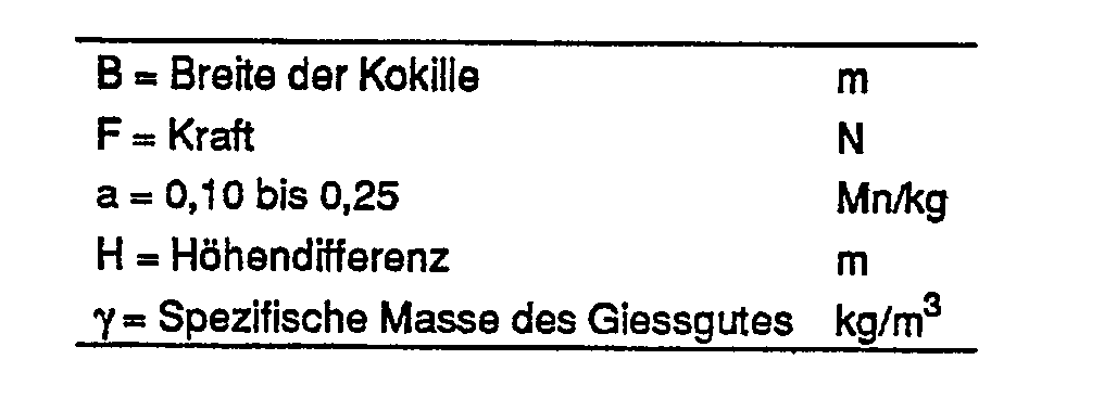
- Die Höhendifferenz entspricht dem Unterschied zwischen der Niveauhöhe im Tundish und der Höhe der unteren Kokillenfläche am Düsenaustritt.
- Die Erfindung wird nun anhand einiger in der Zeichnung dargestellten Ausführungsbeispiele näher erläutert:
- Figur 1 zeigt ein erstes Ausführungsbeispiel im Längsschnitt mit elastischer Anpressung der Kokillenbänder gegen die Giessdüse,
- Figur 2 zeigt eine Teilansicht einer Abdicht- und Kühleinheit von innen, und die
- Figur 3 bis 6 zeigen weitere Ausführungsbeispiele.
- Fig. 1 veranschaulicht eine erste Lösung einer Abdichtung einer Giessdüse gegenüber einem Kokillenband, wobei als Beispiel eine horizontale Giessvorrichtung mit zwei Kokillenbändern gewählt wird. Die Schmelze 10 fliesst durch die Düse 11 in den durch die Kokillenbänder 13 oben und unten begrenzten Giessraum 21. Um eine Ueberhitzung der Kokillenbänder 13 zu verhindern, wird eine wässerige Kühlflüssigkeit aus Druckkammern 18 unter hoher Geschwindigkeit durch Kühlmitteldüsen 19 auf die Rückseite der Kokillenbänder geführt. Um eine spaltfreie Abdichtung des Giessraumes durch die Giessdüse zu gewährleisten, werden die Kokillenbänder 13 mittels einer durch Federn 15, nachgiebig belasteten Leiste 14 gegen das Mundstück der Düse 11 gedrückt.
- Vorteilhafterweise erstreckt sich die Leiste dabei über die ganze Giessbreite der Düse. Die Leiste kann dabei einteilig oder in mehrere Einzelteile von beliebiger Länge geteilt sein. Als Material kann Kunststoff, Metall oder Keramik verwendet werden. Je nach der Abmessung der Düse weist die Leiste vorzugsweise eine Breite von 8 bis 12 mm und eine Höhe in derselben Grössenordnung auf.
- Gemäss Fig. 3 ist die Leiste 14 hydraulisch belastet, wobei Kolben 16 durch Oeffnungen 17 aus der Druckkammer 18 direkt mit der unter Druck stehenden Kühlflüssigkeit beaufschlagt werden. Fig. 3 zeigt eine vertikale Anordnung der Giessvorrichtung.
- Es ist jedoch auch möglich, die Kolben 16 durch ein besonderes Drucksystem hydraulisch oder pneumatisch zu belasten.
- Eine weitere Möglichkeit besteht darin, unter Umgehung der Kolben, das Druckmittel bei entsprechender Abdichtung direkt auf die Leiste 14 wirken zu lassen.
- Werden Federn 15 (Fig. 1) oder Kolben 16 (Fig. 3) angewandt, so werden diese in geeigneter Distanz a (Fig.2) vorgesehen und so bemessen, dass das Kokillenband durch den am Austritt der Düse herrschenden metallostatischen Druck nicht von der Düse abgehoben wird.
- Eine weitere Möglichkeit, ein Kokillenband gegen die Düse zu pressen, besteht darin, dass die Kühlflüssigkeit mit hoher Geschwindigkeit und unter dem Winkel a durch die Kühlmitteldüse 19 direkt auf das Kokillenband wirkt. Fig. 4 zeigt diese Lösung in vertikaler Orientierung. Infolge Umlenkung des Massenstromes der Kühlflüssigkeit um den Winkel a ergibt sich eine auf das Kokillenband wirkende Kraftkomponente. Der Leckverlust der Kühlflüssigkeit nach rückwärts kann mittels einer Labyrinthdichtung 22 in zulässigen Grenzen gehalten werden, wobei die Leckflüssigkeit im Gehäuse der Vorrichtung gesammelt und in das Kühlmittelsystem zurückgeführt werden kann. Der aus der Kühlmitteldüse mit hoher Geschwindigkeit austretende Flüssigkeitsstrom 20 bedeckt mit entsprechender Kühlwirkung die ganze rückseitige Fläche des Kokillenbandes. Die nicht eingezeichnete Führung und Abstützung desselben kann in bekannter Weise erfolgen.
- Eine zusätzliche Variante gemäss Fig. 5 besteht darin, dass der in der Kammer 18 herrschende, statische Flüssigkeitsdruck auf das Kokillenband wirkt und dieses gegen die Giessdüse presst. Dabei strömt die Kühlflüssigkeit auf dem Band 13 direkt aus der unter Druck stehenden Kammer 18 durch die anschliessende Kühlmitteldüse 19. Da die kinetische Energie des Flüssigkeitsstromes in einiger Distanz nach dem Düsenaustritt erschöpft ist, kann in bekannter Art das Kühlmittel in regelmässigen Abständen ersetzt werden.
- Bei geradlinig verlaufenden Kokillenräumen kann die Anpressung der Kokillenbänder auch dadurch erfolgen, dass das Kokillenband so geführt wird, dass es vor der Mündung der Giessdüse gegenüber der Mittellinie derselben in divergierender Richtung läuft und auf der Giessdüse in die Giessrichtung umgelenkt wird, wodurch infolge der Spannung des Kokillenbandes eine auf die Düse wirkende Kraft erzeugt wird. Fig. 6 illustriert eine Lösung dieser Art, indem beide einander gegenüberliegenden Kokillenbänder 13 über Führungen 22 gelenkt werden, deren Distanz a kleiner ist als die Höhe h der Giessdüse. Damit ergibt sich gegenüber der Mittellinie C-C der Giessdüse 11 eine divergierende Richtung des Kokillenbandes 13. Infolge der Spannung derselben in Umfangsrichtung resultiert eine gegen die Giessdüse gerichtete Kraft F.
- Anstelle von festen Führungen 22 können auch Rollen vorgesehen werden.
- Ist A der Querschnitt eines Kokillenbandes, a die in diesem herrschende Zugspannung und β der auf der Giessdüse vorhandene Umlenkwinkel, so wird:

- Weist ein Kokillenband beispielsweise eine Dicke von 0,7 mm und eine Breite von 1000 mm auf, und beträgt die Zugspannung in Umfangsrichtung α = 25 N/mmA2, so wird bei einem Winkel von beispielsweise β = 1 die Anpresskraft auf die Giessdüse

- Auf die praktische Anwendung bezogen, kann damit nach Gleichung (I) ein metallostatischer Druck entsprechend einer flüssigen Metallsäule in der Grössenordnung vom 700 mm Aluminium oder 250 mm Stahl mit Sicherheit abgedichtet werden.
- Durch entsprechende Veränderung der massgebenden Parameter kann die Anpresskraft bei allen vorgängig beschriebenen Lösungen dem am Austritt der Düse herrschenden metallostatischen Druck angepasst werden.
- Unabhängig von den in der Beschreibung angegebenen Methoden der Zuführung der Kühlflüssigkeit auf das Kokillenband, kann das erfindungsgemässe Prinzip der Abdichtung des Giessraumes zwischen Kokillenband und Giessdüse auch bei anderen Kühlmethoden angewandt werden. Beispielsweise kann eine Kühlung auch durch Bespritzen aus in geringen Abständen angeordneten Düsen oder unter Verwendung von sogenannten Tragköpfen, z.B. gemäss EP-A 0 148 384 erfolgen. Da unter Anwendung der vor liegenden Erfindung zwischen der Giessdüse und einem Kokillenband eine gewisse Reibung entsteht, ist es vorteilhaft, auf der Reibstelle der Düse eine verschleissfeste Schicht anzubringen. Dies kann durch bekannte Methoden unter Anwendung der Flamm- oder Plasmaspritztechnik erfolgen, indem eine 0,1 bis 0,2 mm dicke Schicht, z.B. aus Aluminiumoxyd, aufgebracht wird.
- Eine weitere Möglichkeit besteht darin, dass das Mundstück der Düse 11 mit eingelegten Verschleissplatten 12 versehen wird. Hierfür eignen sich Werkstoffe wie Aluminiumoxyd, Siliziumkarbid oder -nitrid, Metallkarbide, u.a.m. Durch eine der erwähnten Massnahmen kann ein vorzeitiger Verschleiss der Giessdüse verhindert werden.
- Die schweizerische Patentschrift Nr. 508 433 beschreibt eine Giessdüse mit in der Nähe der Mündung angebrachten Einlagen aus einem selbstschmierenden Werkstoff. Die Einlagen dienen dabei dem Zweck, das Mundstück zwischen den starren Kokillenhälften einer Raupenkokille so zu führen, dass eine Berührung der Düsenoberfläche mit der Kokille nicht stattfindet, wobei sogar darauf Anspruch erhoben wird, dass die Einlagen aus der Oberfläche der Düse hervorstehen, um eine direkte Berührung der Düsenoberfläche mit der Kokille zu verhindern, indem zwischen Düse und Kokillenfläche ein Spalt von 0,2 bis 0,3 mm vorgesehen wird. Eine Dichtwirkung kann dabei erfahrungsgemäss nur bei einem geringen metallostatischen Druck von höchstens 20 bis 30 mm flüssiger Aluminiumsäule erreicht werden.
- Von der betreffenden Bauart und Wirkungsweise unterscheidet sich die vorliegende Erfindung wesentlich darin, erstens dass die Einlagen nicht aus der Düsenoberfläche hervorstehen, zwitens dass sich die Einlagen so nahe wie möglich am Düsenaustritt befinden und drittens, dass die Einlagen aus einem harten, verschleissfesten Material bestehen, um die Betriebsdauer der Düse unter der Bedingung, dass die Kokillenbänder gegen diese gedrückt werden, zu erhöhen und um eine einwan freie Abdichtung zwischen Düse und Kokillenband bei allen, auch beim Giessen in steigender Richtung praktisch vorkommenden metallostatischen Drücken im Giessraum zu schaffen.
- Wie schon angedeutet, können zwei oder mehr der genannten Massnahmen in Kombination angewendet werden, was z.B. im Falle der Fig. 1 und 3 schon zutrifft, indem sich zu der Anpressung mittels Fedem bzw. Kolben auch eine gewisse hydrostatische und hydrodynamische Anpressung durch die Kühlflüssigkeit addiert. Diese kombinierte Wirkung kann aber noch gesteigert werden.
- Die erfindungsgemässe Anpress- und Abdichtvorrichtung erlaubt, dass im Gegensatz zu den üblichen bekannten Anlagen, die Kühlung der Kokillenbänder erst nach der Anpress- bzw. Abdichtstelle, direkt an der Mündung der Giessdüse 11, also noch im Bereiche der Giessdüse zwischen der Anpressstelle und der Mündung, stattfinden kann. Im Fall der Ausführung nach Fig. 1 und 3 setzt die Kühlung direkt an der Mündung der Giessdüse 11 ein. Damit ist u.a. der Vortil verbunden, dass die Kokillenbänder vorgewärmt in den Bereich der Giessdüse einlaufen und dort nicht mehr stark zusätzlich erhitzt werden. Es können damit Faltenbildungen und sonstige unerwünschte Verformungen der Kokillenbänder infolge starker Wärmedehnung vermieden werden.
- Wie schon gezeigt, ist die Orientierung der Giessvorrichtung bzw. des Giessvorgangs beliebig. Statt horizontal oder vertikal, wie dargestellt, könnte sie auch beliebig geneigt oder aufwärts gerichtet sein. Die erfindungsgemässe Abdichtung hat in jedem Falle den Vorteil, dass man bei geschlossenem Zufuhrsystem der Schmelze mit höheren metallostatischen Drücken arbeiten kann, sei es dass ein relativ hoher Druck infolge der vertikalen Anordnung resultiert, sei es, dass bei horizontaler oder aufwärts verlaufender Giessrichtung das Niveau im Tundish höher als bisher üblich liegt. Die vertikale Anordnung bietet ausserdem Vorteile hinsichtlich symmetrischer Kühlung und überhaupt symmetrischer Verhältnisse beim Giess- und Erstarrungsvorgang. Der höhere Giessdruck führt zu einem sicheren Nachfliessen der Schmelze im Erstarrungsbereich und damit zu einem hochwertigen Gefüge des gegossenen Bandes. Bei Giessvorrichtungen mit zwei Kokillenbändern ist es möglich, eine Anpressung an die Giessdüse auch nur bei einem Kokillenband vorzusehen, und das andere gegenüberliegend mittels einer festen Führung unnachgiebig abzustützen. Das einseitig an die Düse gepresste Kokillenband bewirkt auch ein Aufliegen der Giessdüse auf dem gegenüberliegenden, fest abgestützten Kokillenband, so dass eine Abdichtung auf dieser Seite ebenfalls gewährleistet ist.
- Bisher ist angenommen worden, es erfolge ein Andrücken eines oder zweier Kokillenbänder von aussen gegen die Giessdüse. Es wäre jedoch auch möglich, an den Aussenseitn der Giessdüse genügend hitzebeständige Leisten vorzusehen und dieselben elastisch oder unter metallostatischem Druck von innen gegen die Kokillenbänder anzudrücken, die aussen im Bereiche der Leisten durch starre, beispielsweise durch Kühlwasserdüsen gebildete, Widerlager anliegen. Es ist auch möglich, die Mündung der Giessdüse an sich dehnbar zu gestalten und die Mündungsränder durch den metallostatischen Druck zur Abdichtung gegen die Innenseite der Kokillenbänder zu drücken.
Claims (10)
Priority Applications (1)
| Application Number | Priority Date | Filing Date | Title |
|---|---|---|---|
| AT87810106T ATE43264T1 (de) | 1986-03-10 | 1987-02-23 | Abdichtung einer giessduese gegen den giessraum einer stranggiessvorrichtung mit mindestens einem umlaufenden, flexiblen kokillenband. |
Applications Claiming Priority (2)
| Application Number | Priority Date | Filing Date | Title |
|---|---|---|---|
| CH97286 | 1986-03-10 | ||
| CH972/86 | 1986-03-10 |
Publications (2)
| Publication Number | Publication Date |
|---|---|
| EP0237478A1 EP0237478A1 (de) | 1987-09-16 |
| EP0237478B1 true EP0237478B1 (de) | 1989-05-24 |
Family
ID=4199483
Family Applications (1)
| Application Number | Title | Priority Date | Filing Date |
|---|---|---|---|
| EP87810106A Expired EP0237478B1 (de) | 1986-03-10 | 1987-02-23 | Abdichtung einer Giessdüse gegen den Giessraum einer Stranggiessvorrichtung mit mindestens einem umlaufenden, flexiblen Kokillenband |
Country Status (8)
| Country | Link |
|---|---|
| US (1) | US4785873A (de) |
| EP (1) | EP0237478B1 (de) |
| JP (1) | JP2593470B2 (de) |
| AT (1) | ATE43264T1 (de) |
| CA (1) | CA1293848C (de) |
| DE (1) | DE3760169D1 (de) |
| ES (1) | ES2008705B3 (de) |
| GR (2) | GR890300033T1 (de) |
Families Citing this family (15)
| Publication number | Priority date | Publication date | Assignee | Title |
|---|---|---|---|---|
| DE3703997A1 (de) * | 1987-02-10 | 1988-08-18 | Mannesmann Ag | Vorrichtung zum stranggiessen von duennen straengen aus metall, insbesondere aus stahl |
| CA2128398C (en) * | 1994-07-19 | 2007-02-06 | John Sulzer | Process and apparatus for casting metal strip and injector used therefor |
| US5725046A (en) * | 1994-09-20 | 1998-03-10 | Aluminum Company Of America | Vertical bar caster |
| US5687789A (en) * | 1995-12-28 | 1997-11-18 | Larex A.G. | Caster with improved coil changing system |
| US5787968A (en) * | 1995-12-28 | 1998-08-04 | Larex A.G. | Movably mounted side dam and an associated method of sealing the side dam against the nozzle of a belt caster |
| US5640868A (en) * | 1995-12-28 | 1997-06-24 | Larex A.G. | Apparatus and method for work hardening an endless belt for use in a belt caster |
| US5613547A (en) * | 1996-01-11 | 1997-03-25 | Larex A.G. | Nozzle with a baffle for a caster and an associated method of casting molten metal |
| US5711367A (en) * | 1996-01-11 | 1998-01-27 | Larex A.G. | Apparatus for delivering molten metal to a caster including wear strips |
| US5671801A (en) * | 1996-01-11 | 1997-09-30 | Larex A.G. | Cooling system for a belt caster and associated methods |
| US5778967A (en) * | 1996-01-11 | 1998-07-14 | Larex A.G. | Side dam for a caster having improved contact with solidifying metal |
| US6173755B1 (en) | 1996-05-23 | 2001-01-16 | Aluminum Company Of America | Nozzle for continuous slab casting |
| US5823246A (en) * | 1997-03-03 | 1998-10-20 | Larex A.G. | Tundish including a baffle for directing molten metal therethrough and an associated caster and method of casting molten metal |
| US5967220A (en) * | 1997-03-25 | 1999-10-19 | Larex, A.G. | Caster including a gas delivery means to resist backflowing and freezing of molten metal to the tip of a nozzle |
| DE102010046292A1 (de) | 2009-12-29 | 2011-06-30 | SMS Siemag AG, 40237 | Stranggießanlage und Verfahren zum Stranggießen |
| DE102011078370A1 (de) | 2011-06-29 | 2013-01-03 | Sms Siemag Ag | Verfahren zum Stranggießen eines Gießstrangs und Stranggießanlage |
Family Cites Families (15)
| Publication number | Priority date | Publication date | Assignee | Title |
|---|---|---|---|---|
| FR1418754A (fr) * | 1958-11-19 | 1965-11-26 | Pechiney Prod Chimiques Sa | Améliorations à la technique de la coulée continue |
| CH416955A (de) * | 1964-04-20 | 1966-07-15 | Alusuisse | Verfahren und Maschine zum Stranggiessen von Metallen |
| CH423109A (de) * | 1964-08-31 | 1966-10-31 | Alusuisse | Giessmaschine zur Herstellung von Bändern |
| FR1435936A (fr) * | 1965-03-08 | 1966-04-22 | Siderurgie Fse Inst Rech | Procédé et dispositif de coulée continue de produits liquides |
| US3429363A (en) * | 1966-04-14 | 1969-02-25 | Hazelett Strip Casting Corp | Method of cooling the casting belt in a continuous metal casting machine of the drum and belt type |
| DE1758957A1 (de) * | 1968-09-07 | 1971-04-01 | Schloemann Ag | Stranggiesskokille |
| CH508433A (de) * | 1970-06-24 | 1971-06-15 | Prolizenz Ag C O Schweiz Kredi | Düse für die Zuführung des geschmolzenen Metalles beim Bandgiessen in Raupenkokille |
| US3933193A (en) * | 1971-02-16 | 1976-01-20 | Alcan Research And Development Limited | Apparatus for continuous casting of metal strip between moving belts |
| US3937270A (en) * | 1973-11-09 | 1976-02-10 | Hazelett Strip-Casting Corporation | Twin-belt continuous casting method providing control of the temperature operating conditions at the casting belts |
| JPS582735B2 (ja) * | 1974-07-30 | 1983-01-18 | 古河電気工業株式会社 | レンゾクチユウゾウソウチニオケル チユウユホウホウ |
| DE3029223C2 (de) * | 1980-08-01 | 1984-09-27 | Fried. Krupp Gmbh, 4300 Essen | Einlauf für die Metallschmelze in Stranggießvorrichtungen |
| JPS5820356A (ja) * | 1981-07-29 | 1983-02-05 | Mitsubishi Heavy Ind Ltd | 水平型連続鋳造装置 |
| DE3231321C2 (de) * | 1982-08-23 | 1984-06-07 | Fried. Krupp Gmbh, 4300 Essen | Abdichtung zwischen einer Gießdüse und einer diese umschließenden Stranggießkokille für Stahl mit einem rechteckförmigen Gießquerschnitt |
| JPS59153552A (ja) * | 1983-02-22 | 1984-09-01 | Nippon Kokan Kk <Nkk> | 薄肉鋳片の水平連続鋳造装置 |
| DE3345982C2 (de) * | 1983-12-20 | 1985-11-14 | Fried. Krupp Gmbh, 4300 Essen | Einlauf für die Metallschmelze in Stranggießvorrichtungen, die eine feststehende feuerfeste Gießdüse und eine Kokille mit nur in Gießrichtung bewegten Kokillenwänden aufweisen |
-
1987
- 1987-02-23 EP EP87810106A patent/EP0237478B1/de not_active Expired
- 1987-02-23 DE DE8787810106T patent/DE3760169D1/de not_active Expired
- 1987-02-23 AT AT87810106T patent/ATE43264T1/de not_active IP Right Cessation
- 1987-02-23 ES ES87810106T patent/ES2008705B3/es not_active Expired
- 1987-02-25 CA CA000530521A patent/CA1293848C/en not_active Expired - Lifetime
- 1987-02-26 US US07/019,204 patent/US4785873A/en not_active Expired - Lifetime
- 1987-03-09 JP JP62053914A patent/JP2593470B2/ja not_active Expired - Fee Related
-
1989
- 1989-04-12 GR GR89300033T patent/GR890300033T1/el unknown
- 1989-08-23 GR GR89400154T patent/GR3000131T3/el unknown
Also Published As
| Publication number | Publication date |
|---|---|
| CA1293848C (en) | 1992-01-07 |
| GR890300033T1 (en) | 1989-04-12 |
| ES2008705B3 (es) | 1989-08-01 |
| ATE43264T1 (de) | 1989-06-15 |
| US4785873A (en) | 1988-11-22 |
| JPS62214854A (ja) | 1987-09-21 |
| EP0237478A1 (de) | 1987-09-16 |
| DE3760169D1 (en) | 1989-06-29 |
| GR3000131T3 (en) | 1990-11-29 |
| JP2593470B2 (ja) | 1997-03-26 |
Similar Documents
| Publication | Publication Date | Title |
|---|---|---|
| EP0237478B1 (de) | Abdichtung einer Giessdüse gegen den Giessraum einer Stranggiessvorrichtung mit mindestens einem umlaufenden, flexiblen Kokillenband | |
| DE3719976C2 (de) | ||
| DE1483644B2 (de) | Verfahren zum Gießen von endlosen, breiten Metallplatten und Maschine hierfür | |
| CH624322A5 (en) | Device for cooling and guiding a revolving mould belt in a continuous casting installation | |
| DE2709540A1 (de) | Verfahren zum kuehlen und fuehren eines umlaufenden kokillenbandes an einer vorrichtung zum kontinuierlichen giessen von straengen | |
| EP0233147B1 (de) | Walzgiessverfahren und Walzgiessanlage zur Durchführung desselben | |
| EP3993921A1 (de) | Schmelzezuführung für bandgussanlagen | |
| EP1957220B1 (de) | Verfahren zum betrieb einer zweiwalzengiessmaschine zum vergiessen von metallschmelzen zu gegossenem band | |
| DE3207010A1 (de) | Metallblech-durchlaufgiesseinrichtung | |
| DE68903964T2 (de) | Stranggiessmaschine vom typ raupenkette. | |
| DE3402751C2 (de) | ||
| EP0156764B1 (de) | Elektromagnetische Stranggiesskokille | |
| DE2731748B2 (de) | Rollenführungsgerüst für eine Stahlstranggießanlage | |
| DE4344954C1 (de) | Transportband einer Bandstranggießeinrichtung zum Gießen von Bändern aus Metall | |
| EP1646464B1 (de) | Verfahren zum betrieb einer bandgiessmaschine f r die erzeug ung eines metallbandes | |
| DD201650A5 (de) | Metalleinlauf in stranggiessvorrichtungen mit bewegten kokillenwaenden | |
| DE102008031476A1 (de) | Gießvorrichtung | |
| CH640758A5 (de) | Stranggiessvorrichtung. | |
| EP4452536B1 (de) | Kokille einer stranggiessanlage | |
| DE865940C (de) | Maschine zum Giessen von Metallbaendern u. dgl. | |
| EP3223978B1 (de) | Vorrichtung zum bandgiessen von metallischen produkten | |
| DE19960593C2 (de) | Vorrichtung zum Kühlen eines metallischen Gussstrangs | |
| DE2521218A1 (de) | Oszillierbare kokille mit in stranglaufrichtung kreisbogenfoermigem formhohlraum | |
| CH608731A5 (en) | Continuous casting apparatus, in particular for aluminium plates | |
| DE2613363B2 (de) | Kühlvorrichtung unterhalb einer Stranggießkokille |
Legal Events
| Date | Code | Title | Description |
|---|---|---|---|
| PUAI | Public reference made under article 153(3) epc to a published international application that has entered the european phase |
Free format text: ORIGINAL CODE: 0009012 |
|
| AK | Designated contracting states |
Kind code of ref document: A1 Designated state(s): AT BE CH DE ES FR GB GR IT LI LU NL SE |
|
| 17P | Request for examination filed |
Effective date: 19871002 |
|
| 17Q | First examination report despatched |
Effective date: 19880428 |
|
| GRAA | (expected) grant |
Free format text: ORIGINAL CODE: 0009210 |
|
| AK | Designated contracting states |
Kind code of ref document: B1 Designated state(s): AT BE CH DE ES FR GB GR IT LI LU NL SE |
|
| REF | Corresponds to: |
Ref document number: 43264 Country of ref document: AT Date of ref document: 19890615 Kind code of ref document: T |
|
| ITF | It: translation for a ep patent filed | ||
| REF | Corresponds to: |
Ref document number: 3760169 Country of ref document: DE Date of ref document: 19890629 |
|
| GBT | Gb: translation of ep patent filed (gb section 77(6)(a)/1977) | ||
| ET | Fr: translation filed | ||
| PLBE | No opposition filed within time limit |
Free format text: ORIGINAL CODE: 0009261 |
|
| STAA | Information on the status of an ep patent application or granted ep patent |
Free format text: STATUS: NO OPPOSITION FILED WITHIN TIME LIMIT |
|
| 26N | No opposition filed | ||
| REG | Reference to a national code |
Ref country code: GR Ref legal event code: FG4A Free format text: 3000131 |
|
| ITTA | It: last paid annual fee | ||
| EPTA | Lu: last paid annual fee | ||
| EAL | Se: european patent in force in sweden |
Ref document number: 87810106.2 |
|
| PGFP | Annual fee paid to national office [announced via postgrant information from national office to epo] |
Ref country code: NL Payment date: 20011214 Year of fee payment: 16 |
|
| PGFP | Annual fee paid to national office [announced via postgrant information from national office to epo] |
Ref country code: LU Payment date: 20011221 Year of fee payment: 16 |
|
| REG | Reference to a national code |
Ref country code: GB Ref legal event code: IF02 |
|
| PGFP | Annual fee paid to national office [announced via postgrant information from national office to epo] |
Ref country code: AT Payment date: 20020107 Year of fee payment: 16 |
|
| PGFP | Annual fee paid to national office [announced via postgrant information from national office to epo] |
Ref country code: GB Payment date: 20020108 Year of fee payment: 16 |
|
| PGFP | Annual fee paid to national office [announced via postgrant information from national office to epo] |
Ref country code: GR Payment date: 20020124 Year of fee payment: 16 |
|
| PGFP | Annual fee paid to national office [announced via postgrant information from national office to epo] |
Ref country code: FR Payment date: 20020131 Year of fee payment: 16 |
|
| PGFP | Annual fee paid to national office [announced via postgrant information from national office to epo] |
Ref country code: SE Payment date: 20020201 Year of fee payment: 16 |
|
| PGFP | Annual fee paid to national office [announced via postgrant information from national office to epo] |
Ref country code: ES Payment date: 20020212 Year of fee payment: 16 |
|
| PGFP | Annual fee paid to national office [announced via postgrant information from national office to epo] |
Ref country code: DE Payment date: 20020228 Year of fee payment: 16 |
|
| PGFP | Annual fee paid to national office [announced via postgrant information from national office to epo] |
Ref country code: BE Payment date: 20020318 Year of fee payment: 16 |
|
| PGFP | Annual fee paid to national office [announced via postgrant information from national office to epo] |
Ref country code: CH Payment date: 20020325 Year of fee payment: 16 |
|
| PG25 | Lapsed in a contracting state [announced via postgrant information from national office to epo] |
Ref country code: LU Free format text: LAPSE BECAUSE OF NON-PAYMENT OF DUE FEES Effective date: 20030223 Ref country code: GB Free format text: LAPSE BECAUSE OF NON-PAYMENT OF DUE FEES Effective date: 20030223 Ref country code: AT Free format text: LAPSE BECAUSE OF NON-PAYMENT OF DUE FEES Effective date: 20030223 |
|
| PG25 | Lapsed in a contracting state [announced via postgrant information from national office to epo] |
Ref country code: SE Free format text: LAPSE BECAUSE OF NON-PAYMENT OF DUE FEES Effective date: 20030224 Ref country code: ES Free format text: LAPSE BECAUSE OF NON-PAYMENT OF DUE FEES Effective date: 20030224 |
|
| PG25 | Lapsed in a contracting state [announced via postgrant information from national office to epo] |
Ref country code: LI Free format text: LAPSE BECAUSE OF NON-PAYMENT OF DUE FEES Effective date: 20030228 Ref country code: CH Free format text: LAPSE BECAUSE OF NON-PAYMENT OF DUE FEES Effective date: 20030228 Ref country code: BE Free format text: LAPSE BECAUSE OF NON-PAYMENT OF DUE FEES Effective date: 20030228 |
|
| PG25 | Lapsed in a contracting state [announced via postgrant information from national office to epo] |
Ref country code: NL Free format text: LAPSE BECAUSE OF NON-PAYMENT OF DUE FEES Effective date: 20030901 |
|
| PG25 | Lapsed in a contracting state [announced via postgrant information from national office to epo] |
Ref country code: DE Free format text: LAPSE BECAUSE OF NON-PAYMENT OF DUE FEES Effective date: 20030902 |
|
| PG25 | Lapsed in a contracting state [announced via postgrant information from national office to epo] |
Ref country code: GR Free format text: LAPSE BECAUSE OF NON-PAYMENT OF DUE FEES Effective date: 20030904 |
|
| EUG | Se: european patent has lapsed | ||
| GBPC | Gb: european patent ceased through non-payment of renewal fee | ||
| REG | Reference to a national code |
Ref country code: CH Ref legal event code: PL |
|
| PG25 | Lapsed in a contracting state [announced via postgrant information from national office to epo] |
Ref country code: FR Free format text: LAPSE BECAUSE OF NON-PAYMENT OF DUE FEES Effective date: 20031031 |
|
| NLV4 | Nl: lapsed or anulled due to non-payment of the annual fee |
Effective date: 20030901 |
|
| REG | Reference to a national code |
Ref country code: FR Ref legal event code: ST |
|
| REG | Reference to a national code |
Ref country code: ES Ref legal event code: FD2A Effective date: 20030224 |
|
| PG25 | Lapsed in a contracting state [announced via postgrant information from national office to epo] |
Ref country code: IT Free format text: LAPSE BECAUSE OF NON-PAYMENT OF DUE FEES;WARNING: LAPSES OF ITALIAN PATENTS WITH EFFECTIVE DATE BEFORE 2007 MAY HAVE OCCURRED AT ANY TIME BEFORE 2007. THE CORRECT EFFECTIVE DATE MAY BE DIFFERENT FROM THE ONE RECORDED. Effective date: 20050223 |