EP0237295A1 - Ventilanordnungen - Google Patents
Ventilanordnungen Download PDFInfo
- Publication number
- EP0237295A1 EP0237295A1 EP87301963A EP87301963A EP0237295A1 EP 0237295 A1 EP0237295 A1 EP 0237295A1 EP 87301963 A EP87301963 A EP 87301963A EP 87301963 A EP87301963 A EP 87301963A EP 0237295 A1 EP0237295 A1 EP 0237295A1
- Authority
- EP
- European Patent Office
- Prior art keywords
- valve
- rocker
- axis
- tappet
- valve stem
- Prior art date
- Legal status (The legal status is an assumption and is not a legal conclusion. Google has not performed a legal analysis and makes no representation as to the accuracy of the status listed.)
- Granted
Links
Images


Classifications
-
- F—MECHANICAL ENGINEERING; LIGHTING; HEATING; WEAPONS; BLASTING
- F01—MACHINES OR ENGINES IN GENERAL; ENGINE PLANTS IN GENERAL; STEAM ENGINES
- F01L—CYCLICALLY OPERATING VALVES FOR MACHINES OR ENGINES
- F01L1/00—Valve-gear or valve arrangements, e.g. lift-valve gear
- F01L1/26—Valve-gear or valve arrangements, e.g. lift-valve gear characterised by the provision of two or more valves operated simultaneously by same transmitting-gear; peculiar to machines or engines with more than two lift-valves per cylinder
-
- F—MECHANICAL ENGINEERING; LIGHTING; HEATING; WEAPONS; BLASTING
- F01—MACHINES OR ENGINES IN GENERAL; ENGINE PLANTS IN GENERAL; STEAM ENGINES
- F01L—CYCLICALLY OPERATING VALVES FOR MACHINES OR ENGINES
- F01L1/00—Valve-gear or valve arrangements, e.g. lift-valve gear
- F01L1/02—Valve drive
- F01L1/04—Valve drive by means of cams, camshafts, cam discs, eccentrics or the like
- F01L1/047—Camshafts
- F01L1/053—Camshafts overhead type
-
- F—MECHANICAL ENGINEERING; LIGHTING; HEATING; WEAPONS; BLASTING
- F01—MACHINES OR ENGINES IN GENERAL; ENGINE PLANTS IN GENERAL; STEAM ENGINES
- F01L—CYCLICALLY OPERATING VALVES FOR MACHINES OR ENGINES
- F01L1/00—Valve-gear or valve arrangements, e.g. lift-valve gear
- F01L1/12—Transmitting gear between valve drive and valve
- F01L1/18—Rocking arms or levers
- F01L1/181—Centre pivot rocking arms
-
- F—MECHANICAL ENGINEERING; LIGHTING; HEATING; WEAPONS; BLASTING
- F01—MACHINES OR ENGINES IN GENERAL; ENGINE PLANTS IN GENERAL; STEAM ENGINES
- F01L—CYCLICALLY OPERATING VALVES FOR MACHINES OR ENGINES
- F01L1/00—Valve-gear or valve arrangements, e.g. lift-valve gear
- F01L1/26—Valve-gear or valve arrangements, e.g. lift-valve gear characterised by the provision of two or more valves operated simultaneously by same transmitting-gear; peculiar to machines or engines with more than two lift-valves per cylinder
- F01L1/265—Valve-gear or valve arrangements, e.g. lift-valve gear characterised by the provision of two or more valves operated simultaneously by same transmitting-gear; peculiar to machines or engines with more than two lift-valves per cylinder peculiar to machines or engines with three or more intake valves per cylinder
-
- F—MECHANICAL ENGINEERING; LIGHTING; HEATING; WEAPONS; BLASTING
- F01—MACHINES OR ENGINES IN GENERAL; ENGINE PLANTS IN GENERAL; STEAM ENGINES
- F01L—CYCLICALLY OPERATING VALVES FOR MACHINES OR ENGINES
- F01L3/00—Lift-valve, i.e. cut-off apparatus with closure members having at least a component of their opening and closing motion perpendicular to the closing faces; Parts or accessories thereof
- F01L2003/25—Valve configurations in relation to engine
- F01L2003/251—Large number of valves, e.g. five or more
-
- F—MECHANICAL ENGINEERING; LIGHTING; HEATING; WEAPONS; BLASTING
- F02—COMBUSTION ENGINES; HOT-GAS OR COMBUSTION-PRODUCT ENGINE PLANTS
- F02B—INTERNAL-COMBUSTION PISTON ENGINES; COMBUSTION ENGINES IN GENERAL
- F02B2275/00—Other engines, components or details, not provided for in other groups of this subclass
- F02B2275/20—SOHC [Single overhead camshaft]
-
- F—MECHANICAL ENGINEERING; LIGHTING; HEATING; WEAPONS; BLASTING
- F02—COMBUSTION ENGINES; HOT-GAS OR COMBUSTION-PRODUCT ENGINE PLANTS
- F02B—INTERNAL-COMBUSTION PISTON ENGINES; COMBUSTION ENGINES IN GENERAL
- F02B2275/00—Other engines, components or details, not provided for in other groups of this subclass
- F02B2275/34—Lateral camshaft position
-
- F—MECHANICAL ENGINEERING; LIGHTING; HEATING; WEAPONS; BLASTING
- F02—COMBUSTION ENGINES; HOT-GAS OR COMBUSTION-PRODUCT ENGINE PLANTS
- F02F—CYLINDERS, PISTONS OR CASINGS, FOR COMBUSTION ENGINES; ARRANGEMENTS OF SEALINGS IN COMBUSTION ENGINES
- F02F7/00—Casings, e.g. crankcases or frames
- F02F7/006—Camshaft or pushrod housings
Definitions
- the present invention relates to a poppet valve assembly, for example for a piston-and-cylinder internal combustion engine, in which a plurality of poppet valves are required to be operated simultaneously.
- a poppet valve assembly comprising a plurality of simultaneously operated poppet valve members slidably mounted for movement between their open and closed positions by their stems the axes of which are not all parallel, a rocker mounted for rocking movement about a rocking axis transverse to each valve stem axis, the rocker having a valve stem engaging tappet element for each valve for engaging an end face of the respective valve stem, the respective lengths of the valve stems being such that the tappet elements are not all in the same plane through the rocker axis in such a manner that simultaneously for each valve, in an intermediate part of the valve lift travel, a line from the rocker axis to the point of engagement of the tappet element with the end face of the valve stem is perpendicular to the valve stem axis.
- a poppet valve assembly comprising a plurality of simultaneously operated poppet valve members slidably mounted for movement between their open and closed positions by their stems the axes of which are not all parallel, a rocker mounted for rocking movement about a rocking axis transverse to each said valve stem, the rocker carrying a valve stem engaging tappet element for each valve member for engaging an end face of the respective valve stem, wherein the angular spacing of the valve stem engaging tappet elements around the rocker axis corresponds to the angles between the axes of the respective valve stems and the lengths of the valve stems are such that the tappet elements of the rocker engage the valve stems simultaneously.
- valve stem axes are made equidistant from the rocker axis.
- the cylinder head 1 shown in Figures 1 to 3 is formed by an aluminium alloy casting.
- the casting defines a combustion chamber 2 and inlet and exhaust ducts 3 and 4 which communicate with the combustion chamber 2 through inlet and exhaust ports defined by inlet and exhaust valve seat inserts 5 and 6 respectively.
- the cylinder head casting 1 also defines coolant passages W which receive water-based coolant from a coolant jacket J ( Figure 2) in a cylinder block 7 to which the head is secured and convey the coolant to an outlet 8 ( Figures 1 and 3) in a top surface of the cylinder head.
- a rocker cover (not shown) formed with a central opening to form the upper part of the well 10 is secured over the upper part of the cylinder head to enclosure the valve and rocker mechanism.
- Each of the ports 5 and 6 forms a valve seat for a respective inlet or exhaust poppet valve member 15, 16 respectively.
- the valve members 15 and 16 are of the normal poppet construction with their valve stems slidable in valve guide Inserts 17 and 18 in bores formed in the cylinder head casting coaxially with the respective valve seat inserts 5,6.
- the valve members 15 and 16 are biassed to their closed position, in which their heads make sealing contact with their respective seats 5 and 6, by valve springs 19 and 20 which bear at one end against the upper surface of the cylinder head and at their upper end against washers 21 and 22 which each in turn bear against a split collet (not shown) engaged in a groove near the end of the respective valve stem.
- rockers 23 and 24 which are mounted for rocking movement on pedestal portions 25, 26, 27 and 28 of the cylinder head casting 1, oil being supplied from the lubricating system (not shown) of the engine to the bearings for the rockers through passages 29 formed in the cylinder head and pedestals.
- Each rocker 23,24 is rocked about its axis when its associated valves are to be operated by a respective cam on a camshaft 31 driven at half engine speed.
- Roller-type cam followers 33 and 34 cooperate with the respective cams and transmit their motion through push rods 35 and 36 to operate lever portions 37 and 38 of the rockers 23 and 24.
- the rockers transmit the motion to the valve stems by way of adjustable tappet screws 41 engaged in screw threaded eyes 42 formed integrally with the rockers 23 and 24, the tappet screws 41 being secured after adjustment by means of lock nuts 43.
- the heads of the three inlet valve members 15a, 15b and 15c cannot all be arranged in a straight line without greatly reducing their diameters and thereby reducing the port window area when the valves are opened. Accordingly, they must be arranged in a triangular formation.
- the ports 5a and 5b and their valves 15a and 15b have their axes coplanar.
- the axes of the three valve members must all pass the axis of the rocker at the same or similar distances.
- the axis of the valve 15c is accordingly inclined to the plane through the axis of the valves 15a and 15b at an angle y of about 10°.
- the point of contact of the tappet screw 41c with the valve stem 15c is angularly spaced from the corresponding points of contact between the tappet screws 41a and 41b and their respective valves about the axis 23A of the rocker 23 by the same angle y.
- the stem of the valve 15c must be longer than the stems of the valve 15a and 15b if the heads of all three valves are to form parts, approximately, of the same wall of the combustion chamber 2.
- a plane 50 through the rocker axis 29A and the point of contact of a tappet screw and the end face of Its respective valve stem is at right angles to the axis of the respective valve stem. Normally, this takes place at a point in the range of 30% to 50%, here 35%, of the full valve travel towards Its open position.
- the planes 50a and 50b are of course coincident and are at the angle y to the plane 50c. In the position just described, the points of contact of the tappet screws with their respective valve stems are all at the same distance from the rocker axis 29a.
- the two exhaust valve members are parallel and are thus of the same length so that the corresponding design of their tappet and rocker geometry presents no difficulties.
- the distance between the rocker axis and the axis of the respective valves is made proportional to the required lifts.
- the motions of the three tappets in relation to their valve stems are then geometrically similar and again no compromise is required in their design.
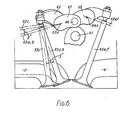
- FIG 6 is a simplified diagram similar to Figure 2 showing the application of the invention to an overhead camshaft engine.
- the inlet and exhaust valves are operated by a single, overhead camshaft 61 (having inlet and exhaust cams).
- an inlet rocker 63 and an exhaust rocker 64 operate respectively three inlet valve members 65a, 65b and 65c and two exhaust valve members 65e and 65f.
- the inlet and exhaust rockers 63 and 64 carry arms 67 and 68 on which are rotatably mounted cam follower rollers 66.
- the axes 63A and 64A of the rockers 63 and 64 lie inboard of the axes of the inlet and exhaust valves.
- the axis of the inlet valve 65c is again inclined at angle y* to the common plane of the axes of the other inlet valves 65a and 65b.
- the central inlet valve member 65c must have a longer stem than the other two inlet valve members 65a and 65b.
- the positions of the upper end faces of the various valve members are indicated in Figure 6 by the reference numeral 62.
- the end faces of the valves 65a and 65b lie in a plane 62a, b while the upper end face of the valve member 65c lies in the plane 70c inclined to the plane 70a,b at the angle y.
- the upper end faces of the exhaust valve 66 pass through a plane 62e, f through the rocker axis 64a during their opening movement.
- Figures 7 and 8 show a modification to the valve gear shown in Figures 1 to 4 in which the manually adjustable screw type tappets are replaced by self-adjusting hydraulic tappets.
- the inlet rocker 23' has a radial drilling 71 in its journal portion 72 supported in the pedestal 25 to receive oil from a drilling in the latter which passes into the interior 73 of the shaft portion of the rocker.
- the journal portion 74 of the rocker which is supported in the pedestal 26 is closed by a plug 75.
- the rocker carries three separate tappet supporting arms 76a, 76b and 76c each of which is formed with a radially extending oil duct 77.
- each rocker arm 76 is formed as an eye 78 in which is housed a hydraulic self-adjusting tappet 80 of the kind available under the trade mark INA.
- This comprises a cylindrical oil reservoir 81 which is open at its upper end to receive oil from the passage 77c.
- a tappet sleeve 82 is slidable in the eye 78 and is a sliding fit around the exterior of the reservoir member 81.
- the lower end of the tappet sleeve 82 is closed by a portion 83 forming a ball portion of a ball and socket joint with the ball portion 83 engaged in a hemispherical seating in a tappet pad 84.
- Oil can pass through a non-return ball valve 85 from the reservoir into a chamber 86 formed between the lower end of the reservoir 81 and the interior of the tappet sleeve 82 so as to keep the chamber 86 full of oil.
- a spring 87 urges the tappet sleeve 82 downwards to bring the tappet pad 84 into contact with the upper end of the stem of the valve member 15.
- the tappet eye 78c is displaced relative to the tappet eye 78a and b by an angle y° with respect to the axis of the rocker and correspondingly the centre 88c of the ball portion 83c is displaced relative to the centres of the ball portions 83a and 83b by the angle y°.
- a partially opened position e.g. at 35X lift
- a line from the rocker axis 73A to the centre 88 of the ball portion 83 is perpendicular to the valve member axis.
- the tappet pad 84 thus forms in effect an extension of the valve stem although the relative lateral 'wiping' motion takes place between the end face of the valve stem and the lower face of the tappet pad.
Applications Claiming Priority (2)
| Application Number | Priority Date | Filing Date | Title |
|---|---|---|---|
| GB8605619 | 1986-03-07 | ||
| GB868605619A GB8605619D0 (en) | 1986-03-07 | 1986-03-07 | Poppet valve assemblies |
Publications (2)
| Publication Number | Publication Date |
|---|---|
| EP0237295A1 true EP0237295A1 (de) | 1987-09-16 |
| EP0237295B1 EP0237295B1 (de) | 1991-02-27 |
Family
ID=10594202
Family Applications (1)
| Application Number | Title | Priority Date | Filing Date |
|---|---|---|---|
| EP87301963A Expired - Lifetime EP0237295B1 (de) | 1986-03-07 | 1987-03-06 | Ventilanordnungen |
Country Status (9)
| Country | Link |
|---|---|
| US (1) | US4819591A (de) |
| EP (1) | EP0237295B1 (de) |
| JP (1) | JPS63502681A (de) |
| KR (1) | KR880701316A (de) |
| AU (1) | AU604235B2 (de) |
| BR (1) | BR8706093A (de) |
| DE (1) | DE3768103D1 (de) |
| GB (1) | GB8605619D0 (de) |
| WO (1) | WO1987005356A1 (de) |
Cited By (7)
| Publication number | Priority date | Publication date | Assignee | Title |
|---|---|---|---|---|
| EP0430259A1 (de) * | 1989-11-29 | 1991-06-05 | Yamaha Hatsudoki Kabushiki Kaisha | Brennkraftmaschine mit mehreren Ventilen |
| EP0430263A1 (de) * | 1989-11-29 | 1991-06-05 | Yamaha Hatsudoki Kabushiki Kaisha | Ventilvorrichtung für Mehrventilbrennkraftmaschine |
| EP0433728A1 (de) * | 1989-11-29 | 1991-06-26 | Yamaha Hatsudoki Kabushiki Kaisha | Zylinderkopf und Ventilanordnung für Mehrventil-Brennkraftmaschine |
| EP0458341A1 (de) * | 1990-05-24 | 1991-11-27 | Mazda Motor Corporation | Zylinderkopf eines Doppelnockenwellenmotors |
| DE4301422A1 (de) * | 1992-01-20 | 1993-07-22 | Mazda Motor | |
| US6055951A (en) * | 1996-05-29 | 2000-05-02 | Ina Walzlager Schaeffler Ohg | Cam follower of a valve train of an internal combustion engine in the form of a finger lever or a rocker arm |
| DE10018561A1 (de) * | 2000-04-14 | 2001-10-18 | Daimler Chrysler Ag | Zylinderkopf für Ventilgesteuerte Hubkolben-Brennkraftmaschinen |
Families Citing this family (16)
| Publication number | Priority date | Publication date | Assignee | Title |
|---|---|---|---|---|
| GB2213196B (en) * | 1987-12-08 | 1991-10-02 | Aston Martin Tickford | Multivalve cylinder head |
| DE3841710C2 (de) * | 1987-12-22 | 1994-09-08 | Bayerische Motoren Werke Ag | Brennkraftmaschine mit einem Querstrom-Zylinderkopf, insbesondere luftgekühlter Einzel-Zylinderkopf für Motorrad-Brennkraftmaschinen |
| JPH088287Y2 (ja) * | 1988-02-22 | 1996-03-06 | 日産自動車株式会社 | Dohc4バルブ型内燃機関のシリンダヘッド |
| JP2917274B2 (ja) * | 1988-03-31 | 1999-07-12 | スズキ株式会社 | 4サイクルエンジンのシリンダヘッド |
| JP2731547B2 (ja) * | 1988-10-19 | 1998-03-25 | ヤマハ発動機株式会社 | 4サイクルエンジン |
| US4907554A (en) * | 1989-01-23 | 1990-03-13 | Bergeron Charles W | Multiple intake poppet valve array for a single port |
| US5359974A (en) * | 1989-11-29 | 1994-11-01 | Yamaha Hatsudoki Kabushiki Kaisha | Single overhead cam multi-valve engine |
| US5007387A (en) * | 1990-01-29 | 1991-04-16 | Masachika Arao | Four valve per cylinder engine head |
| JP3357385B2 (ja) * | 1991-08-27 | 2002-12-16 | マツダ株式会社 | 過給機付きエンジン |
| JP3357384B2 (ja) * | 1991-08-27 | 2002-12-16 | マツダ株式会社 | 火花点火式往復動型エンジン |
| DE69310086T2 (de) * | 1992-10-28 | 1997-07-31 | Yamaha Motor Co Ltd | Zylinderkopf und Ventilanordnung einer Mehrventil-Brennkraftmaschine |
| AT410242B (de) * | 1997-04-09 | 2003-03-25 | Avl List Gmbh | Mehrzylinder-brennkraftmaschine mit zwei einlass- und zwei auslassventilen |
| DE19720350C2 (de) * | 1997-05-15 | 2000-11-02 | Audi Ag | Ventilsystem für eine Mehrventil-Brennkraftmaschine |
| US20050211210A1 (en) * | 2004-03-25 | 2005-09-29 | Masachika Arao | Four valves per cylinder engine head |
| JP2007002739A (ja) * | 2005-06-23 | 2007-01-11 | Honda Motor Co Ltd | エンジン |
| WO2012027248A1 (en) * | 2010-08-26 | 2012-03-01 | Henkel Corporation | A dual cartridge pneumatic dispenser integrated with disposable anti-drip valve for precision dispensing |
Citations (3)
| Publication number | Priority date | Publication date | Assignee | Title |
|---|---|---|---|---|
| FR453876A (fr) * | 1912-05-20 | 1913-06-18 | Fried Krupp Germaniawerft Ag | Distribution pour soupapes de moteurs à combustion interne à deux temps |
| GB1128266A (en) * | 1965-11-17 | 1968-09-25 | Maschf Augsburg Nuernberg Ag | Improvements in or relating to internal combustion engines |
| US4624222A (en) * | 1984-04-11 | 1986-11-25 | Yamaha Hatsudoki Kabushiki Kaisha | Intake valve structure for internal combustion engine |
Family Cites Families (7)
| Publication number | Priority date | Publication date | Assignee | Title |
|---|---|---|---|---|
| US4660529A (en) * | 1981-04-22 | 1987-04-28 | Yamaha Hatsudoki Kabushiki Kaisha | Four-cycle engine |
| JPS58113512A (ja) * | 1981-12-28 | 1983-07-06 | Yamaha Motor Co Ltd | 4サイクルエンジン |
| GB8302520D0 (en) * | 1983-01-29 | 1983-03-02 | Bothwell P W | Ic engine and cylinder head |
| JPS60157946U (ja) * | 1984-03-30 | 1985-10-21 | 株式会社小松製作所 | 油圧駆動車両のエンジン制御装置 |
| JPS611813A (ja) * | 1984-06-12 | 1986-01-07 | Yamaha Motor Co Ltd | 内燃機関の動弁装置 |
| JPS6149120A (ja) * | 1984-08-15 | 1986-03-11 | Yamaha Motor Co Ltd | 4行程内燃機関 |
| JPS6179905A (ja) * | 1984-09-28 | 1986-04-23 | 株式会社日立製作所 | ドレン回収システム |
-
1986
- 1986-03-07 GB GB868605619A patent/GB8605619D0/en active Pending
-
1987
- 1987-03-06 KR KR1019870701018A patent/KR880701316A/ko not_active Application Discontinuation
- 1987-03-06 US US07/135,160 patent/US4819591A/en not_active Expired - Fee Related
- 1987-03-06 AU AU71230/87A patent/AU604235B2/en not_active Ceased
- 1987-03-06 JP JP62501650A patent/JPS63502681A/ja active Pending
- 1987-03-06 EP EP87301963A patent/EP0237295B1/de not_active Expired - Lifetime
- 1987-03-06 WO PCT/GB1987/000159 patent/WO1987005356A1/en unknown
- 1987-03-06 BR BR8706093A patent/BR8706093A/pt unknown
- 1987-03-06 DE DE8787301963T patent/DE3768103D1/de not_active Expired - Fee Related
Patent Citations (3)
| Publication number | Priority date | Publication date | Assignee | Title |
|---|---|---|---|---|
| FR453876A (fr) * | 1912-05-20 | 1913-06-18 | Fried Krupp Germaniawerft Ag | Distribution pour soupapes de moteurs à combustion interne à deux temps |
| GB1128266A (en) * | 1965-11-17 | 1968-09-25 | Maschf Augsburg Nuernberg Ag | Improvements in or relating to internal combustion engines |
| US4624222A (en) * | 1984-04-11 | 1986-11-25 | Yamaha Hatsudoki Kabushiki Kaisha | Intake valve structure for internal combustion engine |
Non-Patent Citations (2)
| Title |
|---|
| PATENT ABSTRACTS OF JAPAN, vol. 10, no. 146 (M-482)[2203], 28th May 1986; & JP-A-61 001 813 (YAMAHA HATSUDOKI K.K.) 07-01-1986 * |
| PATENT ABSTRACTS OF JAPAN, vol. 7, no. 221 (M-246)[1366], 30th September 1983; & JP-A-58 113 512 (YAMAHA HATSUDOKI K.K.) 06-07-1983 * |
Cited By (7)
| Publication number | Priority date | Publication date | Assignee | Title |
|---|---|---|---|---|
| EP0430259A1 (de) * | 1989-11-29 | 1991-06-05 | Yamaha Hatsudoki Kabushiki Kaisha | Brennkraftmaschine mit mehreren Ventilen |
| EP0430263A1 (de) * | 1989-11-29 | 1991-06-05 | Yamaha Hatsudoki Kabushiki Kaisha | Ventilvorrichtung für Mehrventilbrennkraftmaschine |
| EP0433728A1 (de) * | 1989-11-29 | 1991-06-26 | Yamaha Hatsudoki Kabushiki Kaisha | Zylinderkopf und Ventilanordnung für Mehrventil-Brennkraftmaschine |
| EP0458341A1 (de) * | 1990-05-24 | 1991-11-27 | Mazda Motor Corporation | Zylinderkopf eines Doppelnockenwellenmotors |
| DE4301422A1 (de) * | 1992-01-20 | 1993-07-22 | Mazda Motor | |
| US6055951A (en) * | 1996-05-29 | 2000-05-02 | Ina Walzlager Schaeffler Ohg | Cam follower of a valve train of an internal combustion engine in the form of a finger lever or a rocker arm |
| DE10018561A1 (de) * | 2000-04-14 | 2001-10-18 | Daimler Chrysler Ag | Zylinderkopf für Ventilgesteuerte Hubkolben-Brennkraftmaschinen |
Also Published As
| Publication number | Publication date |
|---|---|
| GB8605619D0 (en) | 1986-04-16 |
| KR880701316A (ko) | 1988-07-26 |
| BR8706093A (pt) | 1988-02-09 |
| US4819591A (en) | 1989-04-11 |
| WO1987005356A1 (en) | 1987-09-11 |
| JPS63502681A (ja) | 1988-10-06 |
| EP0237295B1 (de) | 1991-02-27 |
| DE3768103D1 (de) | 1991-04-04 |
| AU7123087A (en) | 1987-09-28 |
| AU604235B2 (en) | 1990-12-13 |
Similar Documents
| Publication | Publication Date | Title |
|---|---|---|
| EP0237295B1 (de) | Ventilanordnungen | |
| US4848285A (en) | Valve operating apparatus for an internal combustion engine | |
| US4621597A (en) | Cylinder head for double overhead cam engine | |
| EP0212981B1 (de) | Anordnung zum Zuführen von Öl zu einem Ventilbetätigungsmechanismus einer Brennkraftmaschine | |
| US4627391A (en) | Engine valve train system | |
| USRE33787E (en) | Four-cycle engine | |
| EP0601250B1 (de) | Hubventilsteuerungsvorrichtung für Brennkraftmaschine | |
| US4327677A (en) | Semi-floating valve bridge | |
| JPH0452847B2 (de) | ||
| US5150672A (en) | Cylinder head of an internal combustion engine | |
| US5864948A (en) | Method for increasing available space for an intake/exhaust port in an internal combustion engine | |
| GB2181486A (en) | Supporting and lubricating i c engine overhead camshafts | |
| KR100299302B1 (ko) | 밸브제어수단 | |
| KR950014406B1 (ko) | 엔진의 밸브구동장치 | |
| US6170449B1 (en) | Valve operating system for engine | |
| EP0199569B1 (de) | Ölzufuhrsystem in einer Brennkraftmaschine | |
| US4721074A (en) | Engine valve train module | |
| DE102008009942A1 (de) | Motor/Ventiltrieb mit an einer Welle angebrachten Nockenstößeln mit dualen unabhängigen Spielausgleichselementen | |
| US5094197A (en) | Timing system, particularly for an internal combustion engine with a number of valves per cyclinder | |
| US1996807A (en) | Valve gear for operating dual valves | |
| US5601057A (en) | Valve actuating system for a multicylinder internal combustion engine | |
| US4741301A (en) | Engine valve train with inner and outer cam followers | |
| US5829400A (en) | Valve gear for an internal combustion engine | |
| US5996541A (en) | Valve control arrangement for an internal combustion engine having lift valves | |
| EP0570963B1 (de) | Variable Ventilsteuervorrichtung für eine Brennkraftmaschine, insbesondere eine Brennkraftmaschine mit mehreren Ventilen je Zylinder |
Legal Events
| Date | Code | Title | Description |
|---|---|---|---|
| PUAI | Public reference made under article 153(3) epc to a published international application that has entered the european phase |
Free format text: ORIGINAL CODE: 0009012 |
|
| AK | Designated contracting states |
Kind code of ref document: A1 Designated state(s): DE ES FR GB IT SE |
|
| 17P | Request for examination filed |
Effective date: 19880311 |
|
| 17Q | First examination report despatched |
Effective date: 19880701 |
|
| GRAA | (expected) grant |
Free format text: ORIGINAL CODE: 0009210 |
|
| AK | Designated contracting states |
Kind code of ref document: B1 Designated state(s): DE ES FR GB IT SE |
|
| PG25 | Lapsed in a contracting state [announced via postgrant information from national office to epo] |
Ref country code: IT Free format text: LAPSE BECAUSE OF FAILURE TO SUBMIT A TRANSLATION OF THE DESCRIPTION OR TO PAY THE FEE WITHIN THE PRE;WARNING: LAPSES OF ITALIAN PATENTS WITH EFFECTIVE DATE BEFORE 2007 MAY HAVE OCCURRED AT ANY TIME BEFORE 2007. THE CORRECT EFFECTIVE DATE MAY BE DIFFERENT FROM THE ONE RECORDED.SCRIBED TIME-LIMIT Effective date: 19910227 Ref country code: FR Effective date: 19910227 |
|
| PGFP | Annual fee paid to national office [announced via postgrant information from national office to epo] |
Ref country code: GB Payment date: 19910227 Year of fee payment: 5 |
|
| PGFP | Annual fee paid to national office [announced via postgrant information from national office to epo] |
Ref country code: SE Payment date: 19910307 Year of fee payment: 5 |
|
| PGFP | Annual fee paid to national office [announced via postgrant information from national office to epo] |
Ref country code: FR Payment date: 19910327 Year of fee payment: 5 |
|
| REF | Corresponds to: |
Ref document number: 3768103 Country of ref document: DE Date of ref document: 19910404 |
|
| PG25 | Lapsed in a contracting state [announced via postgrant information from national office to epo] |
Ref country code: ES Free format text: LAPSE BECAUSE OF FAILURE TO SUBMIT A TRANSLATION OF THE DESCRIPTION OR TO PAY THE FEE WITHIN THE PRESCRIBED TIME-LIMIT Effective date: 19910607 |
|
| EN | Fr: translation not filed | ||
| PLBE | No opposition filed within time limit |
Free format text: ORIGINAL CODE: 0009261 |
|
| STAA | Information on the status of an ep patent application or granted ep patent |
Free format text: STATUS: NO OPPOSITION FILED WITHIN TIME LIMIT |
|
| PG25 | Lapsed in a contracting state [announced via postgrant information from national office to epo] |
Ref country code: DE Effective date: 19920101 |
|
| 26N | No opposition filed | ||
| PG25 | Lapsed in a contracting state [announced via postgrant information from national office to epo] |
Ref country code: GB Effective date: 19920306 |
|
| PG25 | Lapsed in a contracting state [announced via postgrant information from national office to epo] |
Ref country code: SE Effective date: 19920307 |
|
| GBPC | Gb: european patent ceased through non-payment of renewal fee | ||
| EUG | Se: european patent has lapsed |
Ref document number: 87301963.2 Effective date: 19921005 |