EP0234397B1 - Commande numérique des fonctions des machines à coudre ou à broder - Google Patents
Commande numérique des fonctions des machines à coudre ou à broder Download PDFInfo
- Publication number
- EP0234397B1 EP0234397B1 EP19870101807 EP87101807A EP0234397B1 EP 0234397 B1 EP0234397 B1 EP 0234397B1 EP 19870101807 EP19870101807 EP 19870101807 EP 87101807 A EP87101807 A EP 87101807A EP 0234397 B1 EP0234397 B1 EP 0234397B1
- Authority
- EP
- European Patent Office
- Prior art keywords
- needle
- sewn
- transport device
- drive
- motors
- Prior art date
- Legal status (The legal status is an assumption and is not a legal conclusion. Google has not performed a legal analysis and makes no representation as to the accuracy of the status listed.)
- Expired - Lifetime
Links
- 238000009958 sewing Methods 0.000 title claims description 46
- 239000000463 material Substances 0.000 claims description 43
- 230000001105 regulatory effect Effects 0.000 claims description 4
- 238000010586 diagram Methods 0.000 description 12
- 238000000034 method Methods 0.000 description 8
- 230000001419 dependent effect Effects 0.000 description 4
- 238000001208 nuclear magnetic resonance pulse sequence Methods 0.000 description 4
- 239000004744 fabric Substances 0.000 description 3
- 238000004519 manufacturing process Methods 0.000 description 3
- 230000004913 activation Effects 0.000 description 2
- 238000006073 displacement reaction Methods 0.000 description 2
- 238000005259 measurement Methods 0.000 description 2
- 230000003252 repetitive effect Effects 0.000 description 2
- 208000012266 Needlestick injury Diseases 0.000 description 1
- 230000003213 activating effect Effects 0.000 description 1
- 230000015572 biosynthetic process Effects 0.000 description 1
- 238000010276 construction Methods 0.000 description 1
- 238000005034 decoration Methods 0.000 description 1
- 230000003247 decreasing effect Effects 0.000 description 1
- 230000006735 deficit Effects 0.000 description 1
- 230000003111 delayed effect Effects 0.000 description 1
- 239000010985 leather Substances 0.000 description 1
- 230000001360 synchronised effect Effects 0.000 description 1
Images

Classifications
-
- D—TEXTILES; PAPER
- D05—SEWING; EMBROIDERING; TUFTING
- D05B—SEWING
- D05B69/00—Driving-gear; Control devices
- D05B69/22—Devices for stopping drive when sewing tools have reached a predetermined position
Definitions
- the invention relates to a controller for driving the needle bar or needle bars and the sewing material transport or the sewing material transport on embroidery or quilting machines.
- a speed control for the drive motor for the needle bar or needle bars on embroidery, quilting or sewing machines is known, in which the stitch lengths of several pending stitches are queried one after the other from an information carrier, stored serially and measured in cycles. Then the speed of the needle bar drive motor is adapted to the highest of the values measured in a series.
- the needle bar drive motor is designed as a three-phase motor, the speed of which is directly dependent on the frequency of a power supply, which in turn is controlled by the result of each cyclical measurement.
- the power supply for the needle bar drive motor is controlled by a frequency generated in a computer depending on the result of the cyclical measurement.
- a pattern information carrier which has the required values for a contains sample good movement.
- the control generates the command to delay when the next following stitch length retrieved from the pattern information carrier exceeds a value that cannot be carried out for the good of a normal working cycle within the shift phase (German patent specification 32 06 731).
- the disadvantage of this known measure is the fact that the needle drive must be accelerated and decelerated constantly, although it represents the greater mass than that which is predetermined by the transport device for the sewing material.
- This previously known invention therefore relates to a method for at least partially automating a seam production, which is carried out by means of a sewing machine, which has a speed control by means of a step-by-step element and which is equipped with a timer, a sensor for the position of the seam speed control element and a sensor which interacts with a fabric, according to which one first carries out a recording phase of the independent sewing, in order to subsequently produce the seam in a repetitive manner .
- the sensor that interacts with the fabric is a seam length sensor that is used to measure the length of the fabric passing under the needle.
- the recording phase after generally activating the timer, the seam speed control position transmitter and the seam length transmitter, includes storing the instantaneous value of each of these three parameters with each user controlled change in the position of the speed control element, whereas the playback phase consists of continuously recording the time and to record the distance of the seam after a general activation of the sensors.
- the elapsed time is gradually compared with the stored time when the determined position of the speed control element is a zero speed position by reading its stored value, and the seam distance is compared with the stored seam distance when the detected position of the speed control is a non-zero speed position.
- the activation of the three sensors mentioned is controlled at the same time as the lowering of the machine's needle lifter.
- sewing machines are known, both for domestic use and for industrial use, which have a sewing head with thread tensioner, a presser foot, a lower thread roller with a gripper for guiding the lower thread and transport devices for further transport of the sewing material and optionally have additional sewing aids (DE-OS 32 22 716).
- the individual elements have separate drives that can be controlled synchronously by a control device.
- the control device can be constructed on a hydraulic basis or on an electronic basis.
- the aim of this measure is to separate the individual elements such as the sewing head, bobbin thread, looper and transport devices from the other elements, and to position them largely flexibly so that each sewing workstation is optimally equipped in accordance with the respective sewing tasks can be, ie there should not be any impairments caused by systems that are not required for the special sewing work station and sewing operation.
- the present invention is based on the prior art discussed at the outset and aims to simplify control on the one hand and, above all, to even out the running of the machine, in order to achieve a higher working speed in this way.
- this object is achieved by those measures which are the content and subject of claim 1. This ensures that the needle in the subject matter of the invention runs at a predetermined, selectable speed, whereas the sewing material transport is tracked depending on the length of the respective components of the lockstitch, so as to make the running of the machine as uniform as possible and at the same time maximize the working speed achieve.
- the quilting machine which is not shown in detail here, has a needle drive and a drive for the path components X and Y of the sewing material.
- the construction of the quilting machine corresponds to the conventional design.
- a drive motor M N is provided, the speed of which is entered manually via a controller P depending on the respective sewing or step program.
- Two further drive motors M X and M Y serve to move the sewing material, one drive motor M X for the forward and backward movement (X component) of the sewing material and the other drive motor M Y for the lateral back and forth movement (Y -Component).
- Frequency-controlled asynchronous machines, field-regulated DC machines, stepper motors or pulse-controlled synchronous motors are suitable as drive motors.
- AC drive machines are used here, the speed of which is directly dependent on the frequency of the supply voltage, which in turn is influenced by the control device. Such frequency controls are known and are offered on the market.
- Each of the three drive motors M N , M X , M Y is connected to a pulse generator G N , G X , G Y , which feed their pulses to a computer CR during operational use, the number of pulses counting from a certain point in time corresponding adjustment path of the motors M X , M Y corresponds, or a predetermined period of time during which the needle travels a predetermined distance.
- the computer receives the comparison values necessary for it via an information carrier containing the step program, for example a punched tape or a magnetic tape, the respective program values of which are read by a reader L to the computer CR.
- control variables determined by the computer are then partially fed in comparison with the counting pulses of the drive motor to the control elements RM Y and RM X , which in turn act on the drive motors M X and M Y assigned to them in the sense of a speed increase or speed reduction.
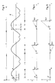
- Fig. 2 illustrates a three stitches S1, S2, S3 comprehensive sequence.
- the position O ' is selected as the starting position and the end position of the sequence corresponds to point C.
- the path components S xn and S yn assigned to the individual stitches S n can be seen directly from the diagram in FIG. You can choose a positive value (moving forward) or a negative value (moving backwards) exhibit. Depending on the length of a stitch S n and its position within the right-angled coordinate system XY, these path components are very different, both in terms of their size and their direction.
- FIG. 3 illustrates the course of the needle N and it should be noted here that the drive motor M N rotates at a constant speed depending on the step program to be carried out, so that the movement of the needle over time t shows a sinusoidal course and The time period T during which the needle makes a complete movement is referred to as the period.
- the speed of the motor M N for the needle drive is set manually via a controller P and depends on the type of program to be carried out.
- line E illustrates the level of the sewing material and it can be seen from the position of this line E in the diagram that the time period t a during which the needle is outside the sewing material is considerably less than the period of time t i during which the needle is inserted into the sewing material and during which the actual stitch is formed, during which the upper and lower threads are intertwined, the means used for this purpose being known boats or grippers.
- the time period t a during which the needle lies outside the sewing material and during which the sewing material can be displaced relative to the needle is only half as long as that time period t i , during which the threads are entwined.
- the two time-distance diagrams according to FIGS. 4 and 5 assigned to the time-path diagram according to FIG. 3 illustrate the stitch components S xn and S yn .
- the first stitch S 1 which extends from O '- A (FIG. 2) and which has only one path component, namely the path component S x1 , it can be seen from the diagrams associated with one another according to FIGS. 3 to 5 that during the first period t a , 3, the sewing material must have traveled the path S x1 in the X direction, whereas no movement is carried out in the Y direction.
- the sewing material must have traveled the path S x1 in the X direction, whereas no movement is carried out in the Y direction.
- these stitches S2 and S3 are preceded by movements in both the X and Y directions.
- the time period available for the respective displacement movement in both the X and Y directions is always t a , this is the time during which the needle, which is driven at a constant speed, lies outside the material to be sewn. Since - as already mentioned - the needle drive is constant, the time period t a available for the respective displacement movement in both the X and Y directions is constant. However, since the distances to be covered during this constant time span are very different (see S xn and S yn in FIGS . 2, 4 and 5), the speed of the adjustment of the sewing material, which is effected by the motors M X and M Y , is per Stitch very different.
- the angles ⁇ and ⁇ in the diagrams according to FIGS. 4 and 5 represent a measure of the respective speed at which this adjustment must be carried out.
- the drive motors M X and M Y can travel the necessary distance depending on the position and length of the respective stitch during the time t a available for the adjustment of the sewing material, they have to track the needle movement continuously.
- the time period t a during which the needle is outside the sewing material corresponds to a pulse sequence of, for example, a hundred pulses.
- Each stitch component S xn or S yn is also assigned a pulse sequence, the number of which is proportional to the length of the respective path, for example the stitch component S x1 is assumed here as a unit length, with a pulse sequence of one hundred pulses.
- the adjustment path in the X direction actually forced by the motor M X is determined by the number of pulses coming from the pulse generator G X.
- the number of pulses I N and I X arriving in the computer CR must be the same, in which case it is guaranteed that at point in time A on the time line t according to FIG. 3, that is, when the needle sticks into the sewing material, the motor M X has adjusted the sewing material by the amount S x1 relative to the needle.
- the controller RM x is activated via the computer CR and the speed of the motor M X is thereby dependent on whether the difference is positive or negative is reduced or increased, so that by the end of the time period t a , that is when the time A is reached, the sewing material in the X direction has completely passed through the path S x1 provided for the stitch S 1 .
- pulse numbers to the time span t a and the unit path length of a stitch, for example a hundred pulses for the time span t a and two hundred pulses for the unit path length S x1 .
- the pulse quantities continuously summed and compared with one another during the time period t a must correspond to one another at the end of the time period t a , that is to say the point A on the time line according to the time-distance diagram according to FIG. 3, that is, at the time A hundred pulses from encoder G N and two hundred pulses from encoder G X have arrived in the computer.
- the path component S y3 is approximately 2.3 times larger than the component S x1 assumed here as the unit path length , that This means that the pulse sequence assigned to the path component S y3 must therefore be 2.3 times larger than that of the standard path length, which is two hundred and thirty pulses here.
- the motor M Y must therefore deliver two hundred and thirty pulses via its pulse generator G Y to the computer CR during the time t a given to it for this distance, which is given to it by the step program that is input via the reader L.
- time t y see FIG.
- the X component S x3 assigned to the stitch S 3 is considerably shorter than the Y component, so that the material can be moved more slowly at the same time in the X direction.
- the difference in speeds results from the comparison of the angles ⁇ '' and ⁇ '', which represent a measure of the adjustment speed.
- control according to the invention is advantageously provided in new embroidery, quilting or sewing machines.
- this control it is entirely possible to design this control as a kit with which existing machines of this type can be retrofitted and equipped in order to design them for a higher working capacity.
- this time period t a can change, since the speed of the needle movement on the respective pattern to be manufactured or on the respective one is to be adapted to the materials to be processed, as has already been mentioned above.
- a ratio of 1: 2 was specified for the two time periods t a and t i .
- the invention can also be used successfully in machines in which this ratio is a different numerical value, for example 1: 3.
Landscapes
- Engineering & Computer Science (AREA)
- Mechanical Engineering (AREA)
- Textile Engineering (AREA)
- Sewing Machines And Sewing (AREA)
Claims (5)
- Commande d'entraînement de la ou des barres d'aiguille et du ou des transporteurs du matériau à piquer sur des machines à coudre ou à broder équipées de moteurs distincts entraînant séparément la barre à aiguille et le transporteur du matériau à piquer, le dispositif de commande comportant des unités de mémoire ainsi que des émetteurs d'impulsions (GN, GX, GY) reliés aux moteurs d'entraînement (MN, MX, MY) de la barre à aiguille et du transporteur du matériau à piquer, les impulsions (IN) pendant un intervalle de temps constant (ta) séparant la sortie de l'aiguille du matériau et sa rentrée dans celui-ci, par l'émetteur (GN) associé au moteur (MN) d'entraînement de la barre à aiguille étant totalisées dans un calculateur (CR), caractérisée en ce qu'à chaque pas de piqûre qui doit être effectué, plus exactement à chacune des composantes (X, Y) de ce pas est associée une série d'impulsions, correspondant à la longueur de la composante, cette série d'impulsions étant adressée par un programmateur contenant le programme de piqûre, par l'intermédiaire d'un lecteur (L) au calculateur (CR), de sorte que s'effectue la comparaison de cette somme, c'est-à-dire de sa valeur instantanée avec le nombre d'impulsions issues des émetteurs (GX, GY) du ou des moteurs (MX, MY) entraînant le transporteur du matériau à coudre et avec le nombre d'impulsions délivrées par l'émetteur (GN) associé au moteur (MN) entraînant la barre à aiguille, de sorte que, à l'apparition d'une différence, le calculateur (CR) fait intervenir un ou plusieurs régulateurs (RMX, RMY) agissant sur les vitesses des moteurs (MX, MY) entraînant le transporteur pour mettre en correspondance le nombre d'impulsions délivrées, pendant un intervalle de temps constant (ta) par le générateur d'impulsions (GN) associé au moteur (MN) entraînant la barre à aiguille et le nombre d'impulsions délivrées par les émetteurs (GX, GY) associés au transporteur du matériau et représentant la longueur du pas de piqûre (SN) suivant à effectuer.
- Commande selon la revendication 1, caractérisée en ce que le transporteur du matériau à piquer est équipé, de manière connue, de moteurs individuels d'entraînement (MX, MY) assurant respectivement une des composantes (X, Y) du mouvement et associés respectivement à un générateur d'impulsions (GX, GY).
- Commande selon une des revendications 1 ou 2, caractérisée en ce que l'entraînement de l'aiguille et/ou du transporteur est assuré par des moteurs (MX, MY) à courant alternatif ou triphasé, a fréquence pilotée.
- Commande selon une des revendications 1 ou 2, caractérisée en ce que l'entraînement de l'aiguille et/ou du transporteur du matériau est associé, de manière connue en soi, par des moteurs pas à pas, à impulsions pilotées.
- Commande selon une des revendications 1 ou 2, caractérisée en ce que l'entraînement de l'aiguille et/ou du transporteur du matériau à piquer est assuré par des moteurs à courant continu, à réglage de champ.
Applications Claiming Priority (2)
| Application Number | Priority Date | Filing Date | Title |
|---|---|---|---|
| AT392/86 | 1986-02-14 | ||
| AT39286A AT399170B (de) | 1986-02-14 | 1986-02-14 | Steuerung für den antrieb der nadelstange bzw. -stangen und des nähguttransportes bzw. der nähguttransporte an stick-, stepp, oder nähmaschinen |
Publications (3)
| Publication Number | Publication Date |
|---|---|
| EP0234397A2 EP0234397A2 (fr) | 1987-09-02 |
| EP0234397A3 EP0234397A3 (en) | 1989-05-24 |
| EP0234397B1 true EP0234397B1 (fr) | 1993-06-16 |
Family
ID=3489380
Family Applications (1)
| Application Number | Title | Priority Date | Filing Date |
|---|---|---|---|
| EP19870101807 Expired - Lifetime EP0234397B1 (fr) | 1986-02-14 | 1987-02-10 | Commande numérique des fonctions des machines à coudre ou à broder |
Country Status (3)
| Country | Link |
|---|---|
| EP (1) | EP0234397B1 (fr) |
| AT (1) | AT399170B (fr) |
| DE (1) | DE3786180D1 (fr) |
Family Cites Families (12)
| Publication number | Priority date | Publication date | Assignee | Title |
|---|---|---|---|---|
| US3450076A (en) * | 1966-10-07 | 1969-06-17 | Thomas A E Bender | Stitching,tufting and carving machine |
| US4120254A (en) * | 1977-09-14 | 1978-10-17 | The Singer Company | Direct drive feed system for sewing machines |
| JPS5923237B2 (ja) * | 1979-06-19 | 1984-05-31 | ユニテツク株式会社 | 自動縫製機における縫製対象物保持枠の駆動装置 |
| DE2942844C2 (de) * | 1979-10-24 | 1987-01-02 | Pfaff Haushaltmaschinen Gmbh, 7500 Karlsruhe | Nähmaschine mit einer Steuereinrichtung für den Antrieb eines Schrittmotors zur Verstellung der Überstichbreite und/oder der Vorschublänge |
| JPS6015354B2 (ja) * | 1979-11-28 | 1985-04-18 | ブラザー工業株式会社 | ミシン |
| DE3020721C2 (de) * | 1980-05-31 | 1982-08-12 | Maschinenfabrik Carl Zangs Ag, 4150 Krefeld | Drehzahlsteuerung des Antriebsmotors für die Bewegung der Nadelstange oder Nadelstangen an Stick-, Stepp- oder Nähmaschinen |
| JPS5789885A (en) * | 1980-11-21 | 1982-06-04 | Janome Sewing Machine Co Ltd | Electronic sewing machine |
| JPS6055148B2 (ja) * | 1981-04-10 | 1985-12-03 | 三菱電機株式会社 | 工業用模様縫いミシン |
| DE3206731C1 (de) * | 1982-02-25 | 1983-04-14 | Maschinenfabrik Carl Zangs Ag, 4150 Krefeld | Stick-, Stepp- oder Nähmaschine |
| DE3222716C2 (de) * | 1982-06-14 | 1986-02-27 | Ortwein, Heinz, Dipl.-Ing., 1000 Berlin | Nähvorrichtung |
| US4413577A (en) * | 1982-11-08 | 1983-11-08 | The Singer Company | Pattern feed balancing arrangement in an electronically controlled sewing machine |
| FR2539431B1 (fr) * | 1983-01-17 | 1986-07-04 | Prouvost Sa | Procede d'automatisation au moins partielle d'une operation de couture et machine partiellement automatisee pour sa mise en oeuvre |
-
1986
- 1986-02-14 AT AT39286A patent/AT399170B/de not_active IP Right Cessation
-
1987
- 1987-02-10 EP EP19870101807 patent/EP0234397B1/fr not_active Expired - Lifetime
- 1987-02-10 DE DE8787101807T patent/DE3786180D1/de not_active Expired - Fee Related
Also Published As
| Publication number | Publication date |
|---|---|
| ATA39286A (de) | 1994-08-15 |
| DE3786180D1 (de) | 1993-07-22 |
| EP0234397A3 (en) | 1989-05-24 |
| EP0234397A2 (fr) | 1987-09-02 |
| AT399170B (de) | 1995-03-27 |
Similar Documents
| Publication | Publication Date | Title |
|---|---|---|
| EP0102524B1 (fr) | Entraînement et dispositif de contrôle de pilotage d'une machine à coudre | |
| DE2646831C2 (de) | Steueranordnung für eine automatische Profilnähmaschine | |
| DE3111113C2 (de) | Regelvorrichtung für den Motor einer das Gewirk beeinflussenden Wickelvorrichtung, wie Teilkettbaum, bei einer Kettenwirkmaschine | |
| DE2744562A1 (de) | Verfahren zur steuerung des einfahrens eines werkzeugs in ein werkstueck in einer zahnradbearbeitungsmaschine und einrichtung zur ausfuehrung des verfahrens | |
| DD213956A5 (de) | Verfahren zum einstellen der strickdichte | |
| DE1485502B2 (de) | Tuftingmaschine zur herstellung von tuftingerzeugnissen mit geschlossenen und aufgeschnittenen schlaufen | |
| DE3811330A1 (de) | Tuftingmaschine | |
| DE1685151A1 (de) | Verfahren und Vorrichtung zur Herstellung von Textilien aus ein- oder mehrfarbigem Flor,insbesondere Florteppichen | |
| DE2621759C3 (de) | Tuftingvorrichtung | |
| DE69619889T2 (de) | Vorrichtung zur Herstellung von Kleidung und Verfahren | |
| DE3039621A1 (de) | Vorrichtung zum tuften | |
| DE69413007T2 (de) | Verfahren zum Steuern vom horizontalen Versatz der Hülsentragbarren in Beziehung mit vorher bestimmten Distanzen zwischen den Nadelmitten an Strickmaschinen | |
| EP0234397B1 (fr) | Commande numérique des fonctions des machines à coudre ou à broder | |
| DE3702050C2 (fr) | ||
| DE1685112A1 (de) | Gesteuerte Zufuehrung des Garnes | |
| DE3020721C2 (de) | Drehzahlsteuerung des Antriebsmotors für die Bewegung der Nadelstange oder Nadelstangen an Stick-, Stepp- oder Nähmaschinen | |
| WO2000066825A1 (fr) | Procede permettant de faire fonctionner une machine a coudre pour assembler une premiere et une deuxieme piece de vetement avec embuvage de la largeur excedentaire | |
| EP0307769B1 (fr) | Métier à tricoter avec dispositif de changement de fils | |
| DE2846035A1 (de) | Steuervorrichtung fuer den transporteur einer naehmaschine | |
| DE3619105A1 (de) | Fadenwechsel-verfahren fuer textilmaschinen | |
| DE1760451A1 (de) | Vorrichtung zum Steppen oder Sticken von Stoffbahnen od.dgl. | |
| DE2361862A1 (de) | Herstellung von vliesstoffen | |
| DE4311531C2 (de) | Verfahren zum Steuern eines Nähautomaten | |
| DE2802527C2 (fr) | ||
| DE2616080C2 (de) | Steuereinheit für eine Flachstrickmaschine |
Legal Events
| Date | Code | Title | Description |
|---|---|---|---|
| PUAI | Public reference made under article 153(3) epc to a published international application that has entered the european phase |
Free format text: ORIGINAL CODE: 0009012 |
|
| AK | Designated contracting states |
Kind code of ref document: A2 Designated state(s): CH DE FR IT LI |
|
| PUAL | Search report despatched |
Free format text: ORIGINAL CODE: 0009013 |
|
| AK | Designated contracting states |
Kind code of ref document: A3 Designated state(s): CH DE FR IT LI |
|
| RHK1 | Main classification (correction) |
Ipc: D05B 19/00 |
|
| 17P | Request for examination filed |
Effective date: 19890713 |
|
| 17Q | First examination report despatched |
Effective date: 19910807 |
|
| GRAA | (expected) grant |
Free format text: ORIGINAL CODE: 0009210 |
|
| AK | Designated contracting states |
Kind code of ref document: B1 Designated state(s): CH DE FR IT LI |
|
| REF | Corresponds to: |
Ref document number: 3786180 Country of ref document: DE Date of ref document: 19930722 |
|
| ET | Fr: translation filed | ||
| ITF | It: translation for a ep patent filed | ||
| PLBE | No opposition filed within time limit |
Free format text: ORIGINAL CODE: 0009261 |
|
| STAA | Information on the status of an ep patent application or granted ep patent |
Free format text: STATUS: NO OPPOSITION FILED WITHIN TIME LIMIT |
|
| 26N | No opposition filed | ||
| PGFP | Annual fee paid to national office [announced via postgrant information from national office to epo] |
Ref country code: CH Payment date: 19960201 Year of fee payment: 10 |
|
| PGFP | Annual fee paid to national office [announced via postgrant information from national office to epo] |
Ref country code: DE Payment date: 19960227 Year of fee payment: 10 |
|
| PGFP | Annual fee paid to national office [announced via postgrant information from national office to epo] |
Ref country code: FR Payment date: 19960229 Year of fee payment: 10 |
|
| PG25 | Lapsed in a contracting state [announced via postgrant information from national office to epo] |
Ref country code: LI Effective date: 19970228 Ref country code: CH Effective date: 19970228 |
|
| REG | Reference to a national code |
Ref country code: CH Ref legal event code: PL |
|
| PG25 | Lapsed in a contracting state [announced via postgrant information from national office to epo] |
Ref country code: FR Effective date: 19971030 |
|
| PG25 | Lapsed in a contracting state [announced via postgrant information from national office to epo] |
Ref country code: DE Effective date: 19971101 |
|
| REG | Reference to a national code |
Ref country code: FR Ref legal event code: ST |
|
| PG25 | Lapsed in a contracting state [announced via postgrant information from national office to epo] |
Ref country code: IT Free format text: LAPSE BECAUSE OF NON-PAYMENT OF DUE FEES Effective date: 20050210 |