EP0234397B1 - Numeric control of sewing machine operation - Google Patents
Numeric control of sewing machine operation Download PDFInfo
- Publication number
- EP0234397B1 EP0234397B1 EP19870101807 EP87101807A EP0234397B1 EP 0234397 B1 EP0234397 B1 EP 0234397B1 EP 19870101807 EP19870101807 EP 19870101807 EP 87101807 A EP87101807 A EP 87101807A EP 0234397 B1 EP0234397 B1 EP 0234397B1
- Authority
- EP
- European Patent Office
- Prior art keywords
- needle
- sewn
- transport device
- drive
- motors
- Prior art date
- Legal status (The legal status is an assumption and is not a legal conclusion. Google has not performed a legal analysis and makes no representation as to the accuracy of the status listed.)
- Expired - Lifetime
Links
- 238000009958 sewing Methods 0.000 title claims description 46
- 239000000463 material Substances 0.000 claims description 43
- 230000001105 regulatory effect Effects 0.000 claims description 4
- 238000010586 diagram Methods 0.000 description 12
- 238000000034 method Methods 0.000 description 8
- 230000001419 dependent effect Effects 0.000 description 4
- 238000001208 nuclear magnetic resonance pulse sequence Methods 0.000 description 4
- 239000004744 fabric Substances 0.000 description 3
- 238000004519 manufacturing process Methods 0.000 description 3
- 230000004913 activation Effects 0.000 description 2
- 238000006073 displacement reaction Methods 0.000 description 2
- 238000005259 measurement Methods 0.000 description 2
- 230000003252 repetitive effect Effects 0.000 description 2
- 208000012266 Needlestick injury Diseases 0.000 description 1
- 230000003213 activating effect Effects 0.000 description 1
- 230000015572 biosynthetic process Effects 0.000 description 1
- 238000010276 construction Methods 0.000 description 1
- 238000005034 decoration Methods 0.000 description 1
- 230000003247 decreasing effect Effects 0.000 description 1
- 230000006735 deficit Effects 0.000 description 1
- 230000003111 delayed effect Effects 0.000 description 1
- 239000010985 leather Substances 0.000 description 1
- 230000001360 synchronised effect Effects 0.000 description 1
Images

Classifications
-
- D—TEXTILES; PAPER
- D05—SEWING; EMBROIDERING; TUFTING
- D05B—SEWING
- D05B69/00—Driving-gear; Control devices
- D05B69/22—Devices for stopping drive when sewing tools have reached a predetermined position
Definitions
- the invention relates to a controller for driving the needle bar or needle bars and the sewing material transport or the sewing material transport on embroidery or quilting machines.
- a speed control for the drive motor for the needle bar or needle bars on embroidery, quilting or sewing machines is known, in which the stitch lengths of several pending stitches are queried one after the other from an information carrier, stored serially and measured in cycles. Then the speed of the needle bar drive motor is adapted to the highest of the values measured in a series.
- the needle bar drive motor is designed as a three-phase motor, the speed of which is directly dependent on the frequency of a power supply, which in turn is controlled by the result of each cyclical measurement.
- the power supply for the needle bar drive motor is controlled by a frequency generated in a computer depending on the result of the cyclical measurement.
- a pattern information carrier which has the required values for a contains sample good movement.
- the control generates the command to delay when the next following stitch length retrieved from the pattern information carrier exceeds a value that cannot be carried out for the good of a normal working cycle within the shift phase (German patent specification 32 06 731).
- the disadvantage of this known measure is the fact that the needle drive must be accelerated and decelerated constantly, although it represents the greater mass than that which is predetermined by the transport device for the sewing material.
- This previously known invention therefore relates to a method for at least partially automating a seam production, which is carried out by means of a sewing machine, which has a speed control by means of a step-by-step element and which is equipped with a timer, a sensor for the position of the seam speed control element and a sensor which interacts with a fabric, according to which one first carries out a recording phase of the independent sewing, in order to subsequently produce the seam in a repetitive manner .
- the sensor that interacts with the fabric is a seam length sensor that is used to measure the length of the fabric passing under the needle.
- the recording phase after generally activating the timer, the seam speed control position transmitter and the seam length transmitter, includes storing the instantaneous value of each of these three parameters with each user controlled change in the position of the speed control element, whereas the playback phase consists of continuously recording the time and to record the distance of the seam after a general activation of the sensors.
- the elapsed time is gradually compared with the stored time when the determined position of the speed control element is a zero speed position by reading its stored value, and the seam distance is compared with the stored seam distance when the detected position of the speed control is a non-zero speed position.
- the activation of the three sensors mentioned is controlled at the same time as the lowering of the machine's needle lifter.
- sewing machines are known, both for domestic use and for industrial use, which have a sewing head with thread tensioner, a presser foot, a lower thread roller with a gripper for guiding the lower thread and transport devices for further transport of the sewing material and optionally have additional sewing aids (DE-OS 32 22 716).
- the individual elements have separate drives that can be controlled synchronously by a control device.
- the control device can be constructed on a hydraulic basis or on an electronic basis.
- the aim of this measure is to separate the individual elements such as the sewing head, bobbin thread, looper and transport devices from the other elements, and to position them largely flexibly so that each sewing workstation is optimally equipped in accordance with the respective sewing tasks can be, ie there should not be any impairments caused by systems that are not required for the special sewing work station and sewing operation.
- the present invention is based on the prior art discussed at the outset and aims to simplify control on the one hand and, above all, to even out the running of the machine, in order to achieve a higher working speed in this way.
- this object is achieved by those measures which are the content and subject of claim 1. This ensures that the needle in the subject matter of the invention runs at a predetermined, selectable speed, whereas the sewing material transport is tracked depending on the length of the respective components of the lockstitch, so as to make the running of the machine as uniform as possible and at the same time maximize the working speed achieve.
- the quilting machine which is not shown in detail here, has a needle drive and a drive for the path components X and Y of the sewing material.
- the construction of the quilting machine corresponds to the conventional design.
- a drive motor M N is provided, the speed of which is entered manually via a controller P depending on the respective sewing or step program.
- Two further drive motors M X and M Y serve to move the sewing material, one drive motor M X for the forward and backward movement (X component) of the sewing material and the other drive motor M Y for the lateral back and forth movement (Y -Component).
- Frequency-controlled asynchronous machines, field-regulated DC machines, stepper motors or pulse-controlled synchronous motors are suitable as drive motors.
- AC drive machines are used here, the speed of which is directly dependent on the frequency of the supply voltage, which in turn is influenced by the control device. Such frequency controls are known and are offered on the market.
- Each of the three drive motors M N , M X , M Y is connected to a pulse generator G N , G X , G Y , which feed their pulses to a computer CR during operational use, the number of pulses counting from a certain point in time corresponding adjustment path of the motors M X , M Y corresponds, or a predetermined period of time during which the needle travels a predetermined distance.
- the computer receives the comparison values necessary for it via an information carrier containing the step program, for example a punched tape or a magnetic tape, the respective program values of which are read by a reader L to the computer CR.
- control variables determined by the computer are then partially fed in comparison with the counting pulses of the drive motor to the control elements RM Y and RM X , which in turn act on the drive motors M X and M Y assigned to them in the sense of a speed increase or speed reduction.
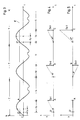
- Fig. 2 illustrates a three stitches S1, S2, S3 comprehensive sequence.
- the position O ' is selected as the starting position and the end position of the sequence corresponds to point C.
- the path components S xn and S yn assigned to the individual stitches S n can be seen directly from the diagram in FIG. You can choose a positive value (moving forward) or a negative value (moving backwards) exhibit. Depending on the length of a stitch S n and its position within the right-angled coordinate system XY, these path components are very different, both in terms of their size and their direction.
- FIG. 3 illustrates the course of the needle N and it should be noted here that the drive motor M N rotates at a constant speed depending on the step program to be carried out, so that the movement of the needle over time t shows a sinusoidal course and The time period T during which the needle makes a complete movement is referred to as the period.
- the speed of the motor M N for the needle drive is set manually via a controller P and depends on the type of program to be carried out.
- line E illustrates the level of the sewing material and it can be seen from the position of this line E in the diagram that the time period t a during which the needle is outside the sewing material is considerably less than the period of time t i during which the needle is inserted into the sewing material and during which the actual stitch is formed, during which the upper and lower threads are intertwined, the means used for this purpose being known boats or grippers.
- the time period t a during which the needle lies outside the sewing material and during which the sewing material can be displaced relative to the needle is only half as long as that time period t i , during which the threads are entwined.
- the two time-distance diagrams according to FIGS. 4 and 5 assigned to the time-path diagram according to FIG. 3 illustrate the stitch components S xn and S yn .
- the first stitch S 1 which extends from O '- A (FIG. 2) and which has only one path component, namely the path component S x1 , it can be seen from the diagrams associated with one another according to FIGS. 3 to 5 that during the first period t a , 3, the sewing material must have traveled the path S x1 in the X direction, whereas no movement is carried out in the Y direction.
- the sewing material must have traveled the path S x1 in the X direction, whereas no movement is carried out in the Y direction.
- these stitches S2 and S3 are preceded by movements in both the X and Y directions.
- the time period available for the respective displacement movement in both the X and Y directions is always t a , this is the time during which the needle, which is driven at a constant speed, lies outside the material to be sewn. Since - as already mentioned - the needle drive is constant, the time period t a available for the respective displacement movement in both the X and Y directions is constant. However, since the distances to be covered during this constant time span are very different (see S xn and S yn in FIGS . 2, 4 and 5), the speed of the adjustment of the sewing material, which is effected by the motors M X and M Y , is per Stitch very different.
- the angles ⁇ and ⁇ in the diagrams according to FIGS. 4 and 5 represent a measure of the respective speed at which this adjustment must be carried out.
- the drive motors M X and M Y can travel the necessary distance depending on the position and length of the respective stitch during the time t a available for the adjustment of the sewing material, they have to track the needle movement continuously.
- the time period t a during which the needle is outside the sewing material corresponds to a pulse sequence of, for example, a hundred pulses.
- Each stitch component S xn or S yn is also assigned a pulse sequence, the number of which is proportional to the length of the respective path, for example the stitch component S x1 is assumed here as a unit length, with a pulse sequence of one hundred pulses.
- the adjustment path in the X direction actually forced by the motor M X is determined by the number of pulses coming from the pulse generator G X.
- the number of pulses I N and I X arriving in the computer CR must be the same, in which case it is guaranteed that at point in time A on the time line t according to FIG. 3, that is, when the needle sticks into the sewing material, the motor M X has adjusted the sewing material by the amount S x1 relative to the needle.
- the controller RM x is activated via the computer CR and the speed of the motor M X is thereby dependent on whether the difference is positive or negative is reduced or increased, so that by the end of the time period t a , that is when the time A is reached, the sewing material in the X direction has completely passed through the path S x1 provided for the stitch S 1 .
- pulse numbers to the time span t a and the unit path length of a stitch, for example a hundred pulses for the time span t a and two hundred pulses for the unit path length S x1 .
- the pulse quantities continuously summed and compared with one another during the time period t a must correspond to one another at the end of the time period t a , that is to say the point A on the time line according to the time-distance diagram according to FIG. 3, that is, at the time A hundred pulses from encoder G N and two hundred pulses from encoder G X have arrived in the computer.
- the path component S y3 is approximately 2.3 times larger than the component S x1 assumed here as the unit path length , that This means that the pulse sequence assigned to the path component S y3 must therefore be 2.3 times larger than that of the standard path length, which is two hundred and thirty pulses here.
- the motor M Y must therefore deliver two hundred and thirty pulses via its pulse generator G Y to the computer CR during the time t a given to it for this distance, which is given to it by the step program that is input via the reader L.
- time t y see FIG.
- the X component S x3 assigned to the stitch S 3 is considerably shorter than the Y component, so that the material can be moved more slowly at the same time in the X direction.
- the difference in speeds results from the comparison of the angles ⁇ '' and ⁇ '', which represent a measure of the adjustment speed.
- control according to the invention is advantageously provided in new embroidery, quilting or sewing machines.
- this control it is entirely possible to design this control as a kit with which existing machines of this type can be retrofitted and equipped in order to design them for a higher working capacity.
- this time period t a can change, since the speed of the needle movement on the respective pattern to be manufactured or on the respective one is to be adapted to the materials to be processed, as has already been mentioned above.
- a ratio of 1: 2 was specified for the two time periods t a and t i .
- the invention can also be used successfully in machines in which this ratio is a different numerical value, for example 1: 3.
Landscapes
- Engineering & Computer Science (AREA)
- Mechanical Engineering (AREA)
- Textile Engineering (AREA)
- Sewing Machines And Sewing (AREA)
Description
Die Erfindung bezieht sich auf eine Steuerung für den Antrieb der Nadelstange bzw. der Nadelstangen und des Nähguttransportes bzw. der Nähguttransporte an Stick- oder Steppmaschinen.The invention relates to a controller for driving the needle bar or needle bars and the sewing material transport or the sewing material transport on embroidery or quilting machines.
Aus der deutschen Patentschrift 30 20 721 ist eine Drehzahlsteuerung für den Antriebsmotor für die Nadelstange oder Nadelstangen an Stick-, Stepp- oder Nähmaschinen bekannt, bei welcher die Stichlängen mehrerer anstehender Stiche aus einem Informationsträger nacheinander abgefragt, seriell gespeichert und taktweise gemessen werden. Dann wird die Drehzahl des Nadelstangenantriebsmotors jeweils dem höchsten der in einer Serie gemessenen Werte angepaßt. Der Nadelstangenantriebsmotor ist als Drehstrommotor ausgebildet, dessen Drehzahl unmittelbar von der Frequenz einer Stromversorgung abhängt, die wiederum vom Ergebnis jeder taktweisen Messung gesteuert wird. Die Steuerung der Stromversorgung für den Nadelstangenantriebsmotor erfolgt dabei durch eine in einem Rechner in Abhängigkeit vom Ergebnis der taktweisen Messung erzeugten Frequenz.From the German patent 30 20 721 a speed control for the drive motor for the needle bar or needle bars on embroidery, quilting or sewing machines is known, in which the stitch lengths of several pending stitches are queried one after the other from an information carrier, stored serially and measured in cycles. Then the speed of the needle bar drive motor is adapted to the highest of the values measured in a series. The needle bar drive motor is designed as a three-phase motor, the speed of which is directly dependent on the frequency of a power supply, which in turn is controlled by the result of each cyclical measurement. The power supply for the needle bar drive motor is controlled by a frequency generated in a computer depending on the result of the cyclical measurement.
Bekannt ist weiterhin eine Stick-, Stepp- oder Nähmaschine, bei der die Verknüpfung von Oberfaden und Unterfaden mittels Greifer bzw. Schiffchen erfolgt, während sich die Nadel im Gut befindet, mit einer Steuerung der Stichbildungsantriebe mittels eines Musterinformationsträgers, der die erforderlichen Werte für eine mustergemäße Gutbewegung enthält. Bei dieser vorbekannten Stick- und Steppmaschine ist der Wiedereintritt der Nadel nach ihrem Austritt aus dem Gut beliebig verzögerbar. Die Steuerung erzeugt den Befehl zur Verzögerung, wenn die nächstfolgende aus dem Musterinformationsträger abgerufene Stichlänge einen Wert übersteigt, der innerhalb der Verschiebephase für das Gut eines normalen Arbeitszyklus nicht durchführbar ist (deutsche Patentschrift 32 06 731). Der Nachteil dieser bekannten Maßnahme ist darin zu sehen, daß der Nadelantrieb ständig beschleunigt und verzögert werden muß, obgleich er die größere Masse darstellt als jene, die mit der Transporteinrichtung für das Nähgut vorgegeben ist.Also known is an embroidery, quilting or sewing machine, in which the upper thread and lower thread are linked by means of a hook or shuttle, while the needle is in the material, with a control of the stitch formation drives by means of a pattern information carrier, which has the required values for a contains sample good movement. With this known embroidery and quilting machine, the re-entry of the needle after it has left the material can be delayed as desired. The control generates the command to delay when the next following stitch length retrieved from the pattern information carrier exceeds a value that cannot be carried out for the good of a normal working cycle within the shift phase (German patent specification 32 06 731). The disadvantage of this known measure is the fact that the needle drive must be accelerated and decelerated constantly, although it represents the greater mass than that which is predetermined by the transport device for the sewing material.
Vor allem ist hier aber das wenigstens zum Teil automatisierte Nähverfahren und die dafür vorgesehene Näheinrichtung nach der EU-OS 117 170 zu erwähnen. Die Erfindung nach dieser Vorveröffentlichung geht von folgenden Gedanken und Überlegungen aus: In der Konfektionsindustrie, bei der Herstellung von Strumpfwirkwaren und von Schuhen, von Lederartikeln, von Erzeugnissen des Sattlerhandwerks, im Bereich von Artikeln der Kinderpflege und selbst bei Möbeln und bei der Dekoration, arbeitet das Personal mit großen Serien völlig identischer Arbeitsvorgänge unter Verwendung von Maschinen zum Nähen oder zum Durchstechen. Dies trifft besonders bei der Kleiderherstellung zu, wo die Aufgaben auf eine Vielzahl von Arbeitsposten verteilt sind, an welchen jeweils eine Arbeiterin den gleichen Vorgang durchführt. Bei jedem dieser Vorgänge ist ein Abschnitt vorhanden, der eine besondere Aufmerksamkeit der Benutzerin der Maschine verlangt, wie beispielsweise ein Nahtende, eine Richtungsänderung oder die Erstellung eines Kragenendes, was eine sehr bedeutsame nervliche Anstrengung darstellt. Die Suche nach einer Erleichterung dieser Anstrengung hat zur Automatisierung dieser sich wiederholenden Vorgänge geführt. Diese vorbekannte Erfindung betrifft daher ein Verfahren zur zumindest teilweisen Automatisierung einer Nahtherstellung, die mittels einer Nähmaschine erfolgt, die eine Geschwindigkeitssteuerung mittels eines stufenweise arbeitenden Elements aufweist und die mit einem Zeitgeber, einem Geber für die Position des Nahtgeschwindigkeitssteuerelementes und einem mit einem Stoff zusammenwirkenden Geber ausgestattet ist, gemäß welchem man zuerst eine Aufzeichnungsphase der selbständig vorzunehmenden Nahtherstellung durchführt, um anschließend in sich wiederholender Weise die Naht herzustellen. Der mit dem Stoff zusammenwirkende Geber ist ein Geber für Nahtlänge, der dazu dient, die Länge des unter der Nadel hindurchtretenden Stoffes zu erfassen. Die Aufzeichnungsphase umfaßt nach allgemeiner Aktivierung des Zeitgebers, des Gebers für die Position des Nahtgeschwindigkeitssteuerelements und des Nahtlängengebers die Speicherung des Augenblickswertes eines jeden dieser drei Parameter bei jeder vom Benutzer gesteuerten Änderung der Position des Geschwindigkeitssteuerelements, wogegen die Wiedergabephase darin besteht, in kontinuierlicher Weise die Zeit und die Strecke der Naht nach einer allgemeinen Aktivierung der Geber zu erfassen. Zur Steuerung der Position des Geschwindigkeitssteuerelements wird die abgelaufene Zeit schrittweise mit der gespeicherten Zeit verglichen, wenn die ermittelte Position des Geschwindigkeitssteuerelements durch Lesen seines gespeicherten Werts eine Position mit der Geschwindigkeit Null ist, und die Nahtstrecke wird mit der gespeicherten Nahtstrecke verglichen, wenn die erfaßte Position des Geschwindigkeitssteuerelements eine Position mit einer Geschwindigkeit ungleich Null ist. Dabei wird die Aktivierung der drei genannten Geber zur gleichen Zeit gesteuert, wie auch das Absenken des Nadelhebers der Maschine. Vereinfacht und mit anderen Worten ausgedrückt handelt es sich also darum, einzelne Arbeitsabläufe innerhalb eines Konfektionsbetriebes im Zuge der Arbeitsvorbereitung aufzunehmen und zu speichern, und die gespeicherten Arbeitsabläufe den einzelnen Näherinnen zuzuteilen. Hier wird also ein sich X-fach wiederholender Nähvorgang im Rahmen eines Konfektionsbetriebes aufgenommen und gespeichert und dann den Näherinnen zur Verfügung gestellt, um ihre Arbeit zu erleichtern.Above all, however, the at least partially automated sewing process and the sewing device provided for it according to EU-OS 117 170 should be mentioned. The invention according to this prior publication is based on the following ideas and considerations: Works in the clothing industry, in the manufacture of hosiery and shoes, of leather articles, of upholstery products, in the area of articles for child care and even for furniture and decoration the staff with large series of completely identical operations using machines for sewing or piercing. This is particularly true in clothing manufacturing, where tasks are spread across a variety of work stations, each with one worker performing the same process. In each of these operations there is a section that requires special attention from the user of the machine, such as a seam end, a change of direction, or the creation of a collar end, which is a very significant nervous effort. The search for a relief from this effort has automated these repetitive processes. This previously known invention therefore relates to a method for at least partially automating a seam production, which is carried out by means of a sewing machine, which has a speed control by means of a step-by-step element and which is equipped with a timer, a sensor for the position of the seam speed control element and a sensor which interacts with a fabric, according to which one first carries out a recording phase of the independent sewing, in order to subsequently produce the seam in a repetitive manner . The sensor that interacts with the fabric is a seam length sensor that is used to measure the length of the fabric passing under the needle. The recording phase, after generally activating the timer, the seam speed control position transmitter and the seam length transmitter, includes storing the instantaneous value of each of these three parameters with each user controlled change in the position of the speed control element, whereas the playback phase consists of continuously recording the time and to record the distance of the seam after a general activation of the sensors. To control the position of the speed control element, the elapsed time is gradually compared with the stored time when the determined position of the speed control element is a zero speed position by reading its stored value, and the seam distance is compared with the stored seam distance when the detected position of the speed control is a non-zero speed position. The activation of the three sensors mentioned is controlled at the same time as the lowering of the machine's needle lifter. In simple terms, in other words, it is a question of recording and saving individual work processes within a clothing factory in the course of work preparation, and of allocating the stored work processes to the individual seamstresses. Here, an X-fold repeating sewing process is recorded and saved as part of a ready-made clothing shop and then made available to the seamstresses to make their work easier.
Schlußendlich ist zum Stand der Technik noch zu erwähnen, daß Nähmaschinen bekannt sind, sowohl für den Hausgebrauch wie auch für den industriellen Einsatz, die einen Nähkopf mit Fadenspanner, einen Drückerfuß, eine Unterfadenrolle mit einem Greifer zur Führung des Unterfadens und Transporteinrichtungen zum Weitertransport des Nähgutes und gegebenenfalls zusätzlicher Nähhilfen aufweisen (DE-OS 32 22 716). Die einzelnen Elemente besitzen dabei getrennte Antriebe, die von einer Steuereinrichtung synchron ansteuerbar sind. Die Steuereinrichtung kann auf hydraulischer Basis oder auf elektronischer Basis aufgebaut sein. Ziel dieser Maßnahme ist es, durch die Trennung der bislang formschlüssigen Kraft- und Bewegungsübertragung die einzelnen Elemente wie Nähkopf, Unterfadenrolle, Greifer und Transporteinrichtungen unabhängig von den anderen Elementen konstruktiv auszugestalten und sie weitgehend flexibel zu positionieren, damit jeder Näharbeitsplatz entsprechend den jeweiligen Nähaufgaben optimal ausgerüstet werden kann, d.h. es sollen keine Beeinträchtigungen durch Systeme entstehen, die für den speziellen Näharbeitsplatz und Näharbeitsgang nicht benötigt werden.Finally, it should be mentioned in relation to the prior art that sewing machines are known, both for domestic use and for industrial use, which have a sewing head with thread tensioner, a presser foot, a lower thread roller with a gripper for guiding the lower thread and transport devices for further transport of the sewing material and optionally have additional sewing aids (DE-OS 32 22 716). The individual elements have separate drives that can be controlled synchronously by a control device. The control device can be constructed on a hydraulic basis or on an electronic basis. The aim of this measure is to separate the individual elements such as the sewing head, bobbin thread, looper and transport devices from the other elements, and to position them largely flexibly so that each sewing workstation is optimally equipped in accordance with the respective sewing tasks can be, ie there should not be any impairments caused by systems that are not required for the special sewing work station and sewing operation.
Die gegenständliche Erfindung geht von dem eingangs erörterten Stand der Technik aus und zielt darauf ab, einerseits die Steuerung zu vereinfachen und andererseits vor allem den Lauf der Maschine zu vergleichmäßigen, um auf diese Weise eine höhere Arbeitsgeschwindigkeit zu erzielen. Gemäß der Erfindung gelingt die Lösung dieser Aufgabe durch jene Maßnahmen, die Inhalt und Gegenstand des Patentanspruches 1 sind. Dadurch wird erreicht, daß die Nadel beim Erfindungsgegenstand mit vorgegebener, wählbarer Geschwindigkeit läuft, wogegen der Nähguttransport in Abhängigkeit der Länge der jeweiligen Komponenten des Steppstiches nachgeführt wird, um so den Lauf der Maschine möglichst zu vergleichmäßigen und dabei gleichzeitig eine maximale Arbeitsgeschwindigkeit zu erzielen.The present invention is based on the prior art discussed at the outset and aims to simplify control on the one hand and, above all, to even out the running of the machine, in order to achieve a higher working speed in this way. According to the invention, this object is achieved by those measures which are the content and subject of claim 1. This ensures that the needle in the subject matter of the invention runs at a predetermined, selectable speed, whereas the sewing material transport is tracked depending on the length of the respective components of the lockstitch, so as to make the running of the machine as uniform as possible and at the same time maximize the working speed achieve.
Anhand der Zeichnung wird die Erfindung im Zusammenhang mit der Steuerung für eine Steppmaschine näher erläutert. Es zeigen:
- Fig. 1 ein Blockschaltbild der Steuerung;
- Fig. 2 eine drei Stiche umfassende Stichfolge und die
- Fig. 3, 4 und 5 Weg-Zeit-Diagramme und zwar für die Nadel und für die X- und Y-Komponenten der Stiche nach der Stichfolge gemäß Fig. 2.
- Fig. 1 is a block diagram of the controller;
- Fig. 2 is a three-stitch sequence and
- 3, 4 and 5 path-time diagrams for the needle and for the X and Y components of the stitches according to the sequence shown in FIG. 2.
Die Steppmaschine, die hier im einzelnen nicht dargestellt ist, besitzt einen Nadelantrieb, sowie je einen Antrieb für die Wegkomponenten X und Y des Nähgutes. Der Aufbau der Steppmaschine entspricht der herkömmlichen Bauart. Für den Antrieb der Nadeln ist ein Antriebsmotor MN vorgesehen, dessen Drehzahl in Abhängigkeit vom jeweiligen Näh- oder Stepprogramm manuell über einen Regler P eingegeben wird. Zwei weitere Antriebsmotoren MX und MY dienen der Bewegung des Nähgutes, wobei der eine Antriebsmotor MX für die Vor- und die Rückwärtsbewegung (X-Komponente) des Nähgutes sorgt und der andere Antriebsmotor MY für die seitliche Hin- und Herbewegung (Y-Komponente). Als Antriebsmotoren eignen sich frequenzgeregelte Asynchronmaschinen, feldgeregelte Gleichstrommaschinen, Schrittmotoren oder pulsrichtergeregelte Synchronmotoren. Im vorstehend beschriebenen Ausführungsbeispiel wird davon ausgegangen, daß hier Wechselstromantriebsmaschinen verwendet werden, deren Drehzahl unmittelbar von der Frequenz der Speisespannung abhängig ist, die ihrerseits durch die Regeleinrichtung beeinflußt wird. Solche Frequenzsteuerungen sind bekannt und werden auf dem Markt angeboten.The quilting machine, which is not shown in detail here, has a needle drive and a drive for the path components X and Y of the sewing material. The construction of the quilting machine corresponds to the conventional design. For driving the needles a drive motor M N is provided, the speed of which is entered manually via a controller P depending on the respective sewing or step program. Two further drive motors M X and M Y serve to move the sewing material, one drive motor M X for the forward and backward movement (X component) of the sewing material and the other drive motor M Y for the lateral back and forth movement (Y -Component). Frequency-controlled asynchronous machines, field-regulated DC machines, stepper motors or pulse-controlled synchronous motors are suitable as drive motors. In the exemplary embodiment described above, it is assumed that AC drive machines are used here, the speed of which is directly dependent on the frequency of the supply voltage, which in turn is influenced by the control device. Such frequency controls are known and are offered on the market.
Jeder der drei Antriebsmotoren MN, MX, MY ist mit einem Impulsgeber GN, GX, GY verbunden, die beim betriebsmäßigen Einsatz ihre Impulse einem Rechner CR zuführen, wobei die Anzahl der von einem bestimmten Zeitpunkt ausgehende Zählung der Impulse einem entsprechenden Verstellweg der Motoren MX, MY entspricht, bzw. einer vorgegebenen Zeitspanne, während der die Nadel einen vorgegebenen Weg zurücklegt. Der Rechner erhält die für ihn notwendigen Vergleichswerte über einen, das Stepprogramm beinhaltenden Informationsträger, beispielsweise einen Lochstreifen oder ein Magnetband, dessen jeweilige Programmwerte von einem Leser L dem Rechner CR zugeleitet werden. Die vom Rechner ermittelten Regelgrößen werden dann partiell im Vergleich mit den Zählimpulsen des Antriebsmotors den Regelgliedern RMY und RMX zugeleitet, die ihrerseits auf die ihnen zugeordneten Antriebsmotoren MX und MY im Sinne einer Drehzahlsteigerung bzw. Drehzahlreduzierung einwirken.Each of the three drive motors M N , M X , M Y is connected to a pulse generator G N , G X , G Y , which feed their pulses to a computer CR during operational use, the number of pulses counting from a certain point in time corresponding adjustment path of the motors M X , M Y corresponds, or a predetermined period of time during which the needle travels a predetermined distance. The computer receives the comparison values necessary for it via an information carrier containing the step program, for example a punched tape or a magnetic tape, the respective program values of which are read by a reader L to the computer CR. The control variables determined by the computer are then partially fed in comparison with the counting pulses of the drive motor to the control elements RM Y and RM X , which in turn act on the drive motors M X and M Y assigned to them in the sense of a speed increase or speed reduction.
Fig. 2 veranschaulicht ein drei Stiche S₁, S₂, S₃ umfassende Stichfolge. Die Position O' ist als Ausgangsposition gewählt und der Endstellung der Stichfolge entspricht Punkt C. Die den einzelnen Stichen Sn zugeordneten Wegkomponenten Sxn und Syn sind dem Diagramm nach Fig.2 direkt entnehmbar. Sie können einen positiven Wert (Vorwärtsbewegung) oder einen negativen Wert (Rückwärtsbewegung) aufweisen. Entsprechend der jeweiligen Länge eines Stiches Sn und entsprechend seiner Lage innerhalb des rechtwinkligen Koordinatensystems X-Y sind diese Wegkomponenten sehr unterschiedlich, sowohl was ihre Größe als auch was ihre Richtung betrifft.Fig. 2 illustrates a three stitches S₁, S₂, S₃ comprehensive sequence. The position O 'is selected as the starting position and the end position of the sequence corresponds to point C. The path components S xn and S yn assigned to the individual stitches S n can be seen directly from the diagram in FIG. You can choose a positive value (moving forward) or a negative value (moving backwards) exhibit. Depending on the length of a stitch S n and its position within the right-angled coordinate system XY, these path components are very different, both in terms of their size and their direction.
Das Diagramm nach Fig. 3 veranschaulicht den Lauf der Nadel N und es ist hier festzuhalten, daß sich der Antriebsmotor MN in Abhängigkeit des durchzuführenden Stepprogrammes mit konstanter Geschwindigkeit dreht, so daß die Bewegung der Nadel über die Zeit t einen sinusartig Verlauf zeigt und die Zeitspanne T, während der die Nadel eine vollständige Bewegung durchführt, als Periode bezeichnet ist. Die Geschwindigkeit des Motors MN für den Nadelantrieb wird über einen Regler P manuell eingestellt und hängt von der Art des abzuführenden Programmes ab. Im Zeit-Weg-Diagramm nach Fig. 3 veranschaulicht die Linie E die Ebene des Nähgutes und es ist aus der Lage dieser Linie E im Diagramm erkennbar, daß die Zeitspanne ta, während der die Nadel außerhalb des Nähgutes ist, erheblich kleiner ist als die Zeitspanne ti, während der die Nadel in das Nähgut eingestochen ist und während der der eigentliche Stich gebildet wird, während der also Ober- und Unterfaden miteinander verschlungen werden, wobei die dazu dienenden Mittel bekannte Schiffchen oder Greifer sind. Das Verhältnis dieser beiden Zeitspannen ![]()
![]()
Die beiden dem Zeit-Weg-Diagramm nach Fig. 3 zugeordneten Zeit-Weg-Diagramme nach den Fig. 4 und 5 veranschaulichen die Stichkomponenten Sxn bzw. Syn.The two time-distance diagrams according to FIGS. 4 and 5 assigned to the time-path diagram according to FIG. 3 illustrate the stitch components S xn and S yn .
Wird der erste Stich S₁ betrachtet, der sich von O' - A erstreckt (Fig. 2) und der nur eine Wegkomponente nämlich die Wegkomponente Sx1 besitzt, so ist aus den einander zugeordneten Diagrammen nach den Fig. 3 bis 5 erkennbar, daß während der ersten Zeitspanne ta, die sich vom Punkt O' - A auf der Zeitlinie t des Diagrammes nach Fig. 3 erstreckt, das Nähgut in der X-Richtung den Weg Sx1 zurückgelegt haben muß, wogegen in der Y-Richtung keine Bewegung durchgeführt wird. Korrespondierendes gilt auch für die nachfolgenden Stiche S₂ und S₃ bzw. der diesen Stichen zugeordneten Wegkomponenten. Diesen Stichen S₂ und S₃ gehen jedoch Bewegungen sowohl in der X- wie auch in der Y-Richtung voraus. Die für die jeweilige Verschiebebewegung sowohl in der X- wie auch in der Y-Richtung zur Verfügung stehende Zeitspanne ist stets ta, dies ist jene Zeit, während der die mit konstanter Geschwindigkeit angetriebene Nadel außerhalb des Nähgutes liegt. Da - wie schon erwähnt - der Nadelantrieb konstant ist, ist die für die jeweilige Verschiebebewegung sowohl in X- wie auch in Y-Richtung zur Verfügung stehende Zeitspanne ta konstant. Da aber die während dieser konstanten Zeitspanne zurückzulegenden Wege sehr unterschiedlich sind (siehe Sxn und Syn in den Fig. 2, 4 und 5) ist die Geschwindigkeit der Verstellung des Nähgutes, die durch die Motoren MX und MY erwirkt wird, pro Stich sehr unterschiedlich. Ein Maß für die jeweilige Geschwindigkeit, in der diese Verstellung abgewickelt werden muß, stellen die Winkel α und β in den Diagrammen nach den Fig. 4 und 5 dar.If the first stitch S 1 is considered, which extends from O '- A (FIG. 2) and which has only one path component, namely the path component S x1 , it can be seen from the diagrams associated with one another according to FIGS. 3 to 5 that during the first period t a , 3, the sewing material must have traveled the path S x1 in the X direction, whereas no movement is carried out in the Y direction. The same applies to the following stitches S₂ and S₃ or the path components assigned to these stitches. However, these stitches S₂ and S₃ are preceded by movements in both the X and Y directions. The time period available for the respective displacement movement in both the X and Y directions is always t a , this is the time during which the needle, which is driven at a constant speed, lies outside the material to be sewn. Since - as already mentioned - the needle drive is constant, the time period t a available for the respective displacement movement in both the X and Y directions is constant. However, since the distances to be covered during this constant time span are very different (see S xn and S yn in FIGS . 2, 4 and 5), the speed of the adjustment of the sewing material, which is effected by the motors M X and M Y , is per Stitch very different. The angles α and β in the diagrams according to FIGS. 4 and 5 represent a measure of the respective speed at which this adjustment must be carried out.
Damit die Antriebsmotoren MX und MY während der für die Verstellung des Nähgutes zur Verfügung stehenden Zeitspanne ta die notwendige und von der Lage und der Länge des jeweiligen Stiches abhängige Wegstrecke durchfahren können, müssen sie ständig der Nadelbewegung nachgeführt werden. Zu diesem Zweck entspricht der Zeitspanne ta, während der die Nadel außerhalb des Nähgutes ist, eine Impulsfolge von beispielsweise hundert Impulsen. Jeder Stichkomponente Sxn bzw. Syn ist ferner eine Impulsfolge zugeordnet, deren Anzahl proportional der Länge der jeweiligen Strecke ist, beispielsweise sei hier die Stichkomponente Sx1 als Einheitslänge vorausgesetzt, mit einer Impulsfolge von hundert Impulsen. Während der ersten Zeitspanne ta (O' - A) gelangen somit vom Impulsgeber GN des Nadelantriebmotors MN hundert Impulse zum Rechner CR. Während dieser Zeit werden vom Informationsträger über den Leser L dem Rechner CR für die Wegkomponente Sx1 hundert Impulse vorgegeben.So that the drive motors M X and M Y can travel the necessary distance depending on the position and length of the respective stitch during the time t a available for the adjustment of the sewing material, they have to track the needle movement continuously. For this purpose, the time period t a during which the needle is outside the sewing material corresponds to a pulse sequence of, for example, a hundred pulses. Each stitch component S xn or S yn is also assigned a pulse sequence, the number of which is proportional to the length of the respective path, for example the stitch component S x1 is assumed here as a unit length, with a pulse sequence of one hundred pulses. During the first period of time t a (O '- A), a hundred pulses thus arrive at the computer CR from the pulse generator G N of the needle drive motor M N. During this time, the information carrier, via the reader L, gives the computer CR a hundred pulses for the path component S x1 .
Der tatsächlich durch den Motor MX erzwungene Verstellweg in der X-Richtung wird durch die Anzahl der vom Impulsgeber GX kommenden Impulse ermittelt. Zu jedem Zeitpunkt tx während der Zeitspanne ta (Fig. 3) müssen die im Rechner CR eintreffenden Impulse IN und IX hinsichtlich ihrer Anzahl gleich sein, in welchem Falle gewährleistet ist, daß zum Zeitpunkt A auf der Zeitlinie t nach Fig. 3, also wenn die Nadel in das Nähgut einsticht, der Motor MX das Nähgut um den Betrag Sx1 gegenüber der Nadel verstellt hat. Liegen zu einem beliebigen Zeitpunkt tx hinsichtlich der Anzahl der eintreffenden Impulse IN und IX Unterschiede vor, so wird über den Rechner CR der Regler RMx aktiviert und dadurch die Drehzahl des Motors MX je nach dem, ob der Unterschied positiv oder negativ ist, reduziert bzw. erhöht, so daß bis zum Ende der Zeitspanne ta, also wenn der Zeitpunkt A erreicht ist, das Nähgut in der X-Richtung den für den Stich S₁ vorgesehenen Weg Sx1 zur Gänze durchfahren hat. In analoger Weise gilt das für den Stich S₁ Geschilderte auch für die nachfolgenden Stiche S₂ und S₃, wobei bei diesen Stichen bzw. bei den für diese Stiche vorgesehenen Verschiebebewegungen in den Richtungen X und Y im Rechner noch zusätzlich die vom Geber GY ankommenden Impulse verarbeitet werden, jedoch in der beschriebenen Weise.The adjustment path in the X direction actually forced by the motor M X is determined by the number of pulses coming from the pulse generator G X. At each point in time t x during the period t a (FIG. 3), the number of pulses I N and I X arriving in the computer CR must be the same, in which case it is guaranteed that at point in time A on the time line t according to FIG. 3, that is, when the needle sticks into the sewing material, the motor M X has adjusted the sewing material by the amount S x1 relative to the needle. If at any time t x there are differences in the number of incoming pulses I N and I X , the controller RM x is activated via the computer CR and the speed of the motor M X is thereby dependent on whether the difference is positive or negative is reduced or increased, so that by the end of the time period t a , that is when the time A is reached, the sewing material in the X direction has completely passed through the path S x1 provided for the stitch S 1 . The same applies to the stitch S₁ also for the subsequent stitches S₂ and S₃, with these stitches or the movement of the stitches provided for these stitches in the directions X and Y in the computer also processes the incoming pulses from the encoder G Y. be, but in the manner described.
Es ist durchaus möglich, der Zeitspanne ta und der Einheitsweglänge eines Stiches unterschiedliche Impulszahlen zuzuordnen, beispielsweise hundert Impulse für die Zeitspanne ta und zweihundert Impulse für die Einheitsweglänge Sx1. Die während der Zeitspanne ta laufend summierten und miteinander verglichenen Impulsmengen müssen am Ende der Zeitspanne ta, das ist der Punkt A auf der Zeitlinie nach dem Zeit-Weg-Diagramm nach Fig.3 einander entsprechen, das heißt, es müssen zum Zeitpunkt A hundert Impulse vom Geber GN und zweihundert Impulse vom Geber GX im Rechner eingelangt sein.It is entirely possible to assign different pulse numbers to the time span t a and the unit path length of a stitch, for example a hundred pulses for the time span t a and two hundred pulses for the unit path length S x1 . The pulse quantities continuously summed and compared with one another during the time period t a must correspond to one another at the end of the time period t a , that is to say the point A on the time line according to the time-distance diagram according to FIG. 3, that is, at the time A hundred pulses from encoder G N and two hundred pulses from encoder G X have arrived in the computer.
Es ist aus den Diagrammen nach den Fig. 4 und 5 ersichtlich, daß beispielsweise die Wegkomponente Sy3 zirka 2,3 mal größer ist, als die hier als Einheitsweglänge angenommene Komponente Sx1, das heißt, die der Wegkomponente Sy3 zugeordnete Impulsfolge muß daher 2,3 mal größer sein als jene der Einheitsweglänge, das ist hier zweihundertdreißig Impulse. Der Motor MY muß also während der ihm für die Zurücklegung dieses Weges vorgegebenen Zeit ta zweihundertdreißig Impulse über seinen Impulsgeber GY an den Rechner CR liefern, die ihm vom Stepprogramm, das über den Leser L eingegeben wird, vorgegeben ist. Zum Zeitpunkt ty (siehe Fig. 3), wenn also die Nadel die Hälfte ihres außerhalb des Nähgutes liegenden Weges zurückgelegt hat, wobei über den ihrem Antriebsmotor MN zugeordneten Impulsgeber GN fünfzig Impulse beim Rechner CR eingelangt sind, müssen über den Geber GY des Antriebsmotors MY hundertfünfzehn Impulse eingetroffen sein, die vom Stepprogramm vorgegeben sind. Falls jedoch zwischen der tatsächlich eingelangten Impulszahl und der vom Imformationsträger für den Weg Sy3 vorgegebenen Impulszahl eine Differenz besteht, wird, wie oben ausgeführt, über den Regler RMY die Drehzahl des Antriebsmotors MY erhöht bzw. erniedrigt, so daß gewährleistet ist, daß am Ende der Zeitspanne ta das Nähgut die Wegkomponente Sy3 zurückgelegt hat. Die dem Stich S₃ zugeordnete X-Komponente Sx3 ist erheblich kürzer als die Y-Komponente, so daß in der X-Richtung gleichzeitig das Nähgut langsamer bewegt werden kann. Der Unterschied der Geschwindigkeiten ergibt sich aus dem Vergleich der Winkel α'' und β'', die ein Maß für die Verstellgeschwindigkeit darstellen.It can be seen from the diagrams according to FIGS. 4 and 5 that, for example, the path component S y3 is approximately 2.3 times larger than the component S x1 assumed here as the unit path length , that This means that the pulse sequence assigned to the path component S y3 must therefore be 2.3 times larger than that of the standard path length, which is two hundred and thirty pulses here. The motor M Y must therefore deliver two hundred and thirty pulses via its pulse generator G Y to the computer CR during the time t a given to it for this distance, which is given to it by the step program that is input via the reader L. At time t y (see FIG. 3), when the needle has traveled half of its path outside the material to be sewn, fifty impulses having arrived at the computer CR via the pulse generator G N associated with its drive motor M N , the transmitter G Y of the drive motor M Y a hundred and fifteen pulses have arrived, which are specified by the step program. However, if there is a difference between the actually received number of pulses and the number of pulses specified by the information carrier for the path S y3 , the speed of the drive motor M Y is increased or decreased via the controller RM Y , so that it is ensured that at the end of the period t a the material has covered the path component S y3 . The X component S x3 assigned to the stitch S 3 is considerably shorter than the Y component, so that the material can be moved more slowly at the same time in the X direction. The difference in speeds results from the comparison of the angles α '' and β '', which represent a measure of the adjustment speed.
Auf diese Weise ist es möglich, den eine große Masse aufweisenden Nadelantrieb mit konstanter Geschwindigkeit anzutreiben und den Nähgutträger bzw. die Nähguttransporteinrichtung, die gegenüber dem Nadelantrieb eine viel geringere Masse aufweist, entsprechend den abzufahrenden Weglängen zu beschleunigen und zu verzögern, wodurch die Bewegung des Nähgutes in optimaler Weise der höchstmöglichen Nähgeschwindigkeit anpaßbar ist. Diese höchstmögliche Nähgeschwindigkeit wird aus der Art des Stepp- oder Nähprogrammes ermittelt und wird manuell über den Drehzahlregler P für den Antriebsmotor MN des Nadelantriebes eingestellt.In this way it is possible to drive the needle drive, which has a large mass, at a constant speed and to accelerate and decelerate the sewing material carrier or the sewing material transport device, which has a much lower mass compared to the needle drive, in accordance with the path lengths to be traveled, as a result of which the movement of the sewing material is optimally adaptable to the highest possible sewing speed. This highest possible sewing speed is determined from the type of quilting or sewing program and is set manually via the speed controller P for the drive motor M N of the needle drive.
Die erfindungsgemäße Steuerung wird zweckmäßig bei neuen Stick-, Stepp- oder Nähmaschinen vorgesehen. Es ist aber durchaus möglich, diese Steuerung als Bausatz zu gestalten, mit welchem bereits vorhandene Maschinen dieser Art nach- und ausgerüstet werden können, um sie so für eine höhere Arbeitskapazität auszulegen.The control according to the invention is advantageously provided in new embroidery, quilting or sewing machines. However, it is entirely possible to design this control as a kit with which existing machines of this type can be retrofitted and equipped in order to design them for a higher working capacity.
Wenn vorstehend von konstanten Zeitspannen die Rede ist, beispielsweise der Zeitspanne ta, während der die Nadel außerhalb des Nähgutes liegt, so gilt dies für ein bestimmtes Muster, das auf der Stick-, Stepp- oder Nähmaschine gerade zu fertigen ist. In Abhängigkeit der Größe und der Ausgestaltung des Musters und/oder in Abhängigkeit von den Materialien, die auf der Maschine verarbeitet werden, kann diese Zeitspanne ta sich ändern, da ja die Geschwindigkeit der Nadelbewegung an das jeweils zu fertigende Muster bzw. an die jeweils zu bearbeitenden Materialien anzupassen ist, wie dies vorstehend schon erwähnt wurde.If there is talk of constant time spans above, for example the time span t a during which the needle lies outside the material to be sewn, this applies to a specific pattern which is currently to be produced on the embroidery, quilting or sewing machine. Depending on the size and design of the pattern and / or depending on the materials that are processed on the machine, this time period t a can change, since the speed of the needle movement on the respective pattern to be manufactured or on the respective one is to be adapted to the materials to be processed, as has already been mentioned above.
Die Erfindung wurde definiert und erläutert unter Bezug auf die erwähnten Zeitspannen. Grundsätzlich ist es möglich, anstelle von Zeitspannen Wegstrecken als Definitionsgrößen heranzuziehen, denn diese beiden physikalischen Größen sind über die jeweilige Geschwindigkeit als Umrechnungsfaktor linear voneinander abhängig.The invention has been defined and explained with reference to the periods mentioned. In principle, it is possible to use distances as definition variables instead of time spans, because these two physical quantities are linearly dependent on each other as a conversion factor via the respective speed.
Beim beschriebenen Ausführungsbeispiel wurde für die beiden Zeitspannen ta und ti ein Verhältnis von 1:2 angegeben. Die Erfindung ist auch bei solchen Maschinen mit Erfolg einsetzbar, bei welchen dieses Verhältnis einen anderen Zahlenwert, beispielsweise 1:3 beträgt.In the exemplary embodiment described, a ratio of 1: 2 was specified for the two time periods t a and t i . The invention can also be used successfully in machines in which this ratio is a different numerical value, for example 1: 3.
Claims (5)
- Control system for the drive of the needle bar or needle bars and of the transport device or devices for the material to be sewn on embroidery or quilting machines, in which separate motors are provided for the needle bar and the transport device for the material to be sewn respectively, in which the control system incorporates impulse transmitters and storage units and the impulse transmitters (GN, GX, GY) are linked to the drive motors (MN, MX, MY) both for the needle bar and for the transport device for the material to be sewn and the pulses (IN) from the impulse transmitter (GN) of the needle bar drive motor (MN), which occur between the emergence of the sewing needle from and its reinsertion into the material to be sewn, are added together in a computer (CR), that a sequence of impulses in proportion to the particular length of the stitch is allocated to each stitch to be performed or its directional components (X, Y) and this sequence of impulses, which is input into the computer (CR) by a reader (L) from an information carrier containing the sewing program, or its instantaneous total is compared with the number of impulses supplied by the impulse transmitter (GX, GY) of the drive motor (MX, MY) or drive motors of the transport device for the material to be sewn and with the number of impulses supplied by the impulse transmitter (GN) of the drive motor (MN) of the needle bar and, in the event of differences, the computer (CR) activates one or more regulators (RMX, RMY), which increase or reduce the rotational speed of the drive motor (MX, MY) or drive motors for the transport device for the material to be sewn, with the result that at the end of the constant time interval (ta) the number of impulses supplied by the impulse transmitter (GN) of the needle drive (MN) and allocated to this time interval (ta) corresponds with the number of impulses supplied by the impulse transmitter (GX, GY) of the transport device for the material to be sewn and allocated to the length of the next stitch (Sn) to be performed.
- Control system in accordance with claim 1, characterised by the fact that the transport device for the material to be sewn incorporates a separate drive (MX, MY) for each component (X, Y) of the movement in a manner already known per se, and an impulse transmitter (GX, GY) is allocated to each of these drives.
- Control system in accordance with one of claims 1 or 2 characterised by the fact that frequency-regulated alternating-current or three-phase-current motors (MX, MY) are provided for driving the needle or for driving the transport device for the material to be sewn.
- Control system in accordance with one of claims 1 or 2, characterised by the fact that impulse-regulated stepping motors (MX, MY) are provided for driving the needle or for driving the transport device for the material to be sewn in a manner already known per se.
- Control system in accordance with one of claims 1 or 2, characterised by the fact that field-regulated direct-current motors (MX, MY) are provided for driving the needle or for driving the transport device for the material to be sewn.
Applications Claiming Priority (2)
| Application Number | Priority Date | Filing Date | Title |
|---|---|---|---|
| AT392/86 | 1986-02-14 | ||
| AT39286A AT399170B (en) | 1986-02-14 | 1986-02-14 | CONTROL FOR THE DRIVE OF THE NEEDLE ROD OR -STANDS AND THE SEWING MATERIAL TRANSPORT OR THE SEWING MATERIAL TRANSPORT ON EMBROIDERY, STEPP, OR SEWING MACHINES |
Publications (3)
| Publication Number | Publication Date |
|---|---|
| EP0234397A2 EP0234397A2 (en) | 1987-09-02 |
| EP0234397A3 EP0234397A3 (en) | 1989-05-24 |
| EP0234397B1 true EP0234397B1 (en) | 1993-06-16 |
Family
ID=3489380
Family Applications (1)
| Application Number | Title | Priority Date | Filing Date |
|---|---|---|---|
| EP19870101807 Expired - Lifetime EP0234397B1 (en) | 1986-02-14 | 1987-02-10 | Numeric control of sewing machine operation |
Country Status (3)
| Country | Link |
|---|---|
| EP (1) | EP0234397B1 (en) |
| AT (1) | AT399170B (en) |
| DE (1) | DE3786180D1 (en) |
Family Cites Families (12)
| Publication number | Priority date | Publication date | Assignee | Title |
|---|---|---|---|---|
| US3450076A (en) * | 1966-10-07 | 1969-06-17 | Thomas A E Bender | Stitching,tufting and carving machine |
| US4120254A (en) * | 1977-09-14 | 1978-10-17 | The Singer Company | Direct drive feed system for sewing machines |
| JPS5923237B2 (en) * | 1979-06-19 | 1984-05-31 | ユニテツク株式会社 | Drive device for holding frame for sewing object in automatic sewing machine |
| DE2942844C2 (en) * | 1979-10-24 | 1987-01-02 | Pfaff Haushaltmaschinen Gmbh, 7500 Karlsruhe | Sewing machine with a control device for driving a stepper motor for adjusting the stitch width and/or the feed length |
| JPS6015354B2 (en) * | 1979-11-28 | 1985-04-18 | ブラザー工業株式会社 | sewing machine |
| DE3020721C2 (en) * | 1980-05-31 | 1982-08-12 | Maschinenfabrik Carl Zangs Ag, 4150 Krefeld | Speed control of the drive motor for moving the needle bar or needle bars on embroidery, quilting or sewing machines |
| JPS5789885A (en) * | 1980-11-21 | 1982-06-04 | Janome Sewing Machine Co Ltd | Electronic sewing machine |
| JPS6055148B2 (en) * | 1981-04-10 | 1985-12-03 | 三菱電機株式会社 | industrial pattern sewing machine |
| DE3206731C1 (en) * | 1982-02-25 | 1983-04-14 | Maschinenfabrik Carl Zangs Ag, 4150 Krefeld | Embroidering, quilting or sewing machine |
| DE3222716C2 (en) * | 1982-06-14 | 1986-02-27 | Ortwein, Heinz, Dipl.-Ing., 1000 Berlin | Sewing device |
| US4413577A (en) * | 1982-11-08 | 1983-11-08 | The Singer Company | Pattern feed balancing arrangement in an electronically controlled sewing machine |
| FR2539431B1 (en) * | 1983-01-17 | 1986-07-04 | Prouvost Sa | METHOD FOR AT LEAST PARTIAL AUTOMATION OF A SEWING OPERATION AND PARTIALLY AUTOMATED MACHINE FOR ITS IMPLEMENTATION |
-
1986
- 1986-02-14 AT AT39286A patent/AT399170B/en not_active IP Right Cessation
-
1987
- 1987-02-10 EP EP19870101807 patent/EP0234397B1/en not_active Expired - Lifetime
- 1987-02-10 DE DE8787101807T patent/DE3786180D1/en not_active Expired - Fee Related
Also Published As
| Publication number | Publication date |
|---|---|
| ATA39286A (en) | 1994-08-15 |
| DE3786180D1 (en) | 1993-07-22 |
| EP0234397A3 (en) | 1989-05-24 |
| EP0234397A2 (en) | 1987-09-02 |
| AT399170B (en) | 1995-03-27 |
Similar Documents
| Publication | Publication Date | Title |
|---|---|---|
| EP0102524B1 (en) | Sewing machine driving and controlling device | |
| DE2646831C2 (en) | Control arrangement for an automatic profile sewing machine | |
| DE3111113C2 (en) | Control device for the motor of a winding device that influences the knitted fabric, such as a partial warp beam, in a warp knitting machine | |
| DE2744562A1 (en) | METHOD FOR CONTROLLING THE RUNNING OF A TOOL INTO A WORKPIECE IN A GEAR MACHINING MACHINE AND DEVICE FOR EXECUTING THE METHOD | |
| DD213956A5 (en) | METHOD FOR ADJUSTING THE KNITTED DENSITY | |
| DE1485502B2 (en) | TUFTING MACHINE FOR THE PRODUCTION OF TUFTING PRODUCTS WITH CLOSED AND CUT LOOPS | |
| DE3811330A1 (en) | TUFTING MACHINE | |
| DE1685151A1 (en) | Method and device for the production of textiles from single or multi-colored pile, in particular pile carpets | |
| DE2621759C3 (en) | Tufting device | |
| DE69619889T2 (en) | Device for the production of clothing and processes | |
| DE3039621A1 (en) | DEVICE FOR THE TUFT | |
| DE69413007T2 (en) | Method for controlling the horizontal offset of the core bars in relation to predetermined distances between the centers of the needles on knitting machines | |
| EP0234397B1 (en) | Numeric control of sewing machine operation | |
| DE3702050C2 (en) | ||
| DE1685112A1 (en) | Controlled feeding of the yarn | |
| DE3020721C2 (en) | Speed control of the drive motor for moving the needle bar or needle bars on embroidery, quilting or sewing machines | |
| WO2000066825A1 (en) | Method for operating a sewing machine for joining a first part of a sewn article to a second part of a sewn article and integrating excess width at the same time | |
| EP0307769B1 (en) | Knitting machine with a thread-changing device | |
| DE2846035A1 (en) | CONTROL DEVICE FOR THE CONVEYOR OF A SEWING MACHINE | |
| DE3619105A1 (en) | Thread-changing method for textile machines | |
| DE1760451A1 (en) | Device for quilting or embroidery of fabric or the like. | |
| DE2361862A1 (en) | MANUFACTURE OF NON-WOVEN FABRICS | |
| DE4311531C2 (en) | Process for controlling an automatic sewing machine | |
| DE2802527C2 (en) | ||
| DE2616080C2 (en) | Control unit for a flat knitting machine |
Legal Events
| Date | Code | Title | Description |
|---|---|---|---|
| PUAI | Public reference made under article 153(3) epc to a published international application that has entered the european phase |
Free format text: ORIGINAL CODE: 0009012 |
|
| AK | Designated contracting states |
Kind code of ref document: A2 Designated state(s): CH DE FR IT LI |
|
| PUAL | Search report despatched |
Free format text: ORIGINAL CODE: 0009013 |
|
| AK | Designated contracting states |
Kind code of ref document: A3 Designated state(s): CH DE FR IT LI |
|
| RHK1 | Main classification (correction) |
Ipc: D05B 19/00 |
|
| 17P | Request for examination filed |
Effective date: 19890713 |
|
| 17Q | First examination report despatched |
Effective date: 19910807 |
|
| GRAA | (expected) grant |
Free format text: ORIGINAL CODE: 0009210 |
|
| AK | Designated contracting states |
Kind code of ref document: B1 Designated state(s): CH DE FR IT LI |
|
| REF | Corresponds to: |
Ref document number: 3786180 Country of ref document: DE Date of ref document: 19930722 |
|
| ET | Fr: translation filed | ||
| ITF | It: translation for a ep patent filed | ||
| PLBE | No opposition filed within time limit |
Free format text: ORIGINAL CODE: 0009261 |
|
| STAA | Information on the status of an ep patent application or granted ep patent |
Free format text: STATUS: NO OPPOSITION FILED WITHIN TIME LIMIT |
|
| 26N | No opposition filed | ||
| PGFP | Annual fee paid to national office [announced via postgrant information from national office to epo] |
Ref country code: CH Payment date: 19960201 Year of fee payment: 10 |
|
| PGFP | Annual fee paid to national office [announced via postgrant information from national office to epo] |
Ref country code: DE Payment date: 19960227 Year of fee payment: 10 |
|
| PGFP | Annual fee paid to national office [announced via postgrant information from national office to epo] |
Ref country code: FR Payment date: 19960229 Year of fee payment: 10 |
|
| PG25 | Lapsed in a contracting state [announced via postgrant information from national office to epo] |
Ref country code: LI Effective date: 19970228 Ref country code: CH Effective date: 19970228 |
|
| REG | Reference to a national code |
Ref country code: CH Ref legal event code: PL |
|
| PG25 | Lapsed in a contracting state [announced via postgrant information from national office to epo] |
Ref country code: FR Effective date: 19971030 |
|
| PG25 | Lapsed in a contracting state [announced via postgrant information from national office to epo] |
Ref country code: DE Effective date: 19971101 |
|
| REG | Reference to a national code |
Ref country code: FR Ref legal event code: ST |
|
| PG25 | Lapsed in a contracting state [announced via postgrant information from national office to epo] |
Ref country code: IT Free format text: LAPSE BECAUSE OF NON-PAYMENT OF DUE FEES Effective date: 20050210 |