EP0234318B1 - Dispositif de préchauffage de l'air d'admission dans un moteur diesel à plusieurs cylindres - Google Patents
Dispositif de préchauffage de l'air d'admission dans un moteur diesel à plusieurs cylindres Download PDFInfo
- Publication number
- EP0234318B1 EP0234318B1 EP87101172A EP87101172A EP0234318B1 EP 0234318 B1 EP0234318 B1 EP 0234318B1 EP 87101172 A EP87101172 A EP 87101172A EP 87101172 A EP87101172 A EP 87101172A EP 0234318 B1 EP0234318 B1 EP 0234318B1
- Authority
- EP
- European Patent Office
- Prior art keywords
- engine
- pressure
- valve
- fuel
- preheating
- Prior art date
- Legal status (The legal status is an assumption and is not a legal conclusion. Google has not performed a legal analysis and makes no representation as to the accuracy of the status listed.)
- Expired - Lifetime
Links
Images


Classifications
-
- F—MECHANICAL ENGINEERING; LIGHTING; HEATING; WEAPONS; BLASTING
- F02—COMBUSTION ENGINES; HOT-GAS OR COMBUSTION-PRODUCT ENGINE PLANTS
- F02N—STARTING OF COMBUSTION ENGINES; STARTING AIDS FOR SUCH ENGINES, NOT OTHERWISE PROVIDED FOR
- F02N19/00—Starting aids for combustion engines, not otherwise provided for
- F02N19/02—Aiding engine start by thermal means, e.g. using lighted wicks
- F02N19/04—Aiding engine start by thermal means, e.g. using lighted wicks by heating of fluids used in engines
- F02N19/06—Aiding engine start by thermal means, e.g. using lighted wicks by heating of fluids used in engines by heating of combustion-air by flame generating means, e.g. flame glow-plugs
- F02N19/08—Arrangement thereof
-
- F—MECHANICAL ENGINEERING; LIGHTING; HEATING; WEAPONS; BLASTING
- F02—COMBUSTION ENGINES; HOT-GAS OR COMBUSTION-PRODUCT ENGINE PLANTS
- F02B—INTERNAL-COMBUSTION PISTON ENGINES; COMBUSTION ENGINES IN GENERAL
- F02B3/00—Engines characterised by air compression and subsequent fuel addition
- F02B3/06—Engines characterised by air compression and subsequent fuel addition with compression ignition
-
- Y—GENERAL TAGGING OF NEW TECHNOLOGICAL DEVELOPMENTS; GENERAL TAGGING OF CROSS-SECTIONAL TECHNOLOGIES SPANNING OVER SEVERAL SECTIONS OF THE IPC; TECHNICAL SUBJECTS COVERED BY FORMER USPC CROSS-REFERENCE ART COLLECTIONS [XRACs] AND DIGESTS
- Y02—TECHNOLOGIES OR APPLICATIONS FOR MITIGATION OR ADAPTATION AGAINST CLIMATE CHANGE
- Y02T—CLIMATE CHANGE MITIGATION TECHNOLOGIES RELATED TO TRANSPORTATION
- Y02T10/00—Road transport of goods or passengers
- Y02T10/10—Internal combustion engine [ICE] based vehicles
- Y02T10/12—Improving ICE efficiencies
Definitions
- the invention relates to a device for preheating the intake air of a multi-cylinder diesel engine, in which a thermoelectric ignition device and a high-pressure fuel atomizer are arranged in the intake manifold of the engine, which via a pipeline and a high-pressure bleed valve with the pressure side of the injection pump of the engine can be connected, the injection nozzles of which are connected to the injection pump via pressure pipes.
- start pilots in which a material (gas) with a low ignition point (low compression tolerance) is admixed with the intake air.
- a generic device for preheating the intake air in which the total amount of fuel delivered by all the injection pumps is either taken from the pressure chamber of a distributor injection pump or taken from each high-pressure line between the injection pump and the injection nozzle and is led into a common manifold, after which in the first start phase the diverted fuel is finely atomized via the flame candle and injected into the intake manifold of the engine via a heating coil that ignites the fuel.
- the fuel supply to the intake manifold is interrupted in the second starting phase and the engine can run idle for a few revolutions, which means that the exhaust gases in the intake manifold and cylinder compartment are flushed out by the fresh air drawn in.
- the third start phase in which fuel is finally injected into the cylinder, which can ignite solely by compression.
- a disadvantage of this preheating device is that the fresh air is not heated up at the same time and the ignition can take place, which has a long starting time.
- you have to heat more than is actually necessary since the fresh air sucked in in the third starting phase to start the engine is only heated by the heated suction pipe and the heated cylinder.
- the combustion of the total amount of fuel delivered by all injection pumps in the intake manifold is often accompanied by soot.
- the invention solves the problem of creating a generic device for preheating the intake air of a multi-cylinder diesel engine, in which simultaneous starting of the engine and preheating of the intake fresh air is ensured with optimal combustion of the fuel fed into the intake manifold for this purpose.
- the high-pressure bleed valve is an adjustable, the preheating fuel quantity controlling valve, which is switched into the pressure pipe between the injection pump of the engine and the injection nozzle, only one of the cylinders, with the high-pressure bleed valve only such a partial quantity of the fuel is fed into the intake manifold, that the hot air / combustion product mixture has the oxygen content necessary for the engine to start and that the engine injection nozzles are supplied with the amount of fuel required for starting during this preheating phase.
- the device according to the invention advantageously has such a high-pressure bleed valve, in the valve housing of which pressure pipe connections with screw threads are connected to one another via flow bores, and which have a valve body arranged on a valve seat which is formed on one of these flow bores and arranged on the valve housing and in the valve housing valve press connected via a screw thread and provided with a driver connection.
- An actuating bolt which is provided with a driver and a valve disk, is connected to this valve press and is pressed by a spring against the perforated cover provided with the valve seat.
- the valve chamber is connected via a bore to a threaded tap on the valve housing.
- Any atomizer that works on the principle of pressure atomization and is known per se can be used as the fuel atomizer connected to the intake manifold, including an injection nozzle commonly used in diesel engines.
- the fuel atomizer connected to the intake manifold and the thermoelectric ignition device can be designed as one structural unit.
- a construction can advantageously be used in which one end of the atomizer body has a threaded connection, which is connected via a bore to an annular channel formed at the other end of the atomizer body and surrounding a wart, which channel is connected to the wart by means of a bore provided membrane is completed.
- This membrane mentioned is pressed against the atomizer body by an atomizer housing, a perforated jacket being connected to the atomizer housing, which surrounds one opposite the bore of the membrane, one end being grounded and the other end surrounding an electric filament which is insulated for electrical connection.
- the device according to the invention finds its primary application in diesel engines with direct injection, where the electrical glow plug which facilitates cold starting (starting under cold temperatures) cannot be arranged in the combustion chamber for design reasons.
- the device according to the invention can Any diesel engine provided with an injection pump can be easily and subsequently installed, so the cold start properties of the diesel motor vehicles already in operation can be significantly increased.
- the temperature limit for the startability of the diesel engine is reduced by the use of the inventive device by approximately 10-20 0th
- thermoelectric ignition device due to the low electrical power consumption of the thermoelectric ignition device, the accumulator is hardly loaded during starting and therefore more electrical power remains for the starter.
- the device according to the invention is also advantageous because the intake air or the engine is preheated by the heat generated during the combustion of the fuel of the engine, that is, the cold start does not require any separate additional material, means or external energy source.
- the device according to the invention can be designed in such a way that it can be operated (operated) by one person from the driver's seat and that the operation (operation) as a whole with the operation of the starting aid used in diesel engines with a divided combustion chamber (preheating with glow plug) agrees what is a routine practice for all drivers.
- a fuel atomizer 2 is connected to an intake manifold 1 of a diesel engine, and a thermoelectric ignition device 3 (electric filament) is arranged in the atomizing jet.
- a pipeline 4 is connected to the fuel atomizer 2 and is connected via a bleed valve 5 to a pressure pipe 8 leading from an injection pump 6 to an injection nozzle 7 associated with a cylinder.
- the bleed valve 5 is suitable for partially or wholly guiding the fuel dose to the injector 7 to the fuel atomizer 2.
- the bleed valve 5 Before starting, the bleed valve 5 is brought into such a position that it opens the pressure pipe 8 to the fuel atomizer 2.
- the thermoelectric ignition device 3 is energized and after the thermoelectric ignition device (the electric filament) has been heated up, the diesel engine is started.
- the fuel When metering takes place in the pressure pipe 8, the fuel is brought by the fuel atomizer 2 in the form of a fine trickle into the air in the suction pipe and onto the electric filament 3, upon the action of which the fuel is ignited and burned, thereby causing the suction pipe and the air therein air is heated.
- the piston which is just moving in the intake stroke, sucks in this mixture of warm air and combustion product, which has sufficient heat content that at the end of the compression stroke of the same cylinder the ignition temperature of the injected fuel is exceeded and the engine starts.
- the oxygen content of the warm air / combustion product mixture sucked into the cylinder, which is necessary for starting the engine, is ensured by the appropriate choice of the arrangement of the fuel atomizer 2 and by an adapted amount of fuel which is drawn off by opening the bleed valve 5.
- the fuel burned in the intake manifold heats the intake manifold to such an extent during a few engine revolutions that air with a heat content required for temperability not only gets into the cylinder after the atomization in the intake manifold but also into the other cylinders.
- the thermoelectric ignition device 3 is de-energized and the bleed valve 5 is brought into the closed state, so that the injection nozzle 7 connected to the pressure pipe 8 can also start metering into the associated cylinder.
- the bleed valve 5 is also suitable for a partial bleeding of the fuel quantity (dose) delivered by the injection pump 6 through the pressure pipe 8 to the injection nozzle 7. This can expediently be achieved by means of a variable throttle. Furthermore, it should be ensured that the bleed valve 5 is appropriately sealed against the outside space both in the closed and in the open state and during operation against the pressure occurring therein (in some cases a few hundred bars).
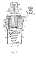
- FIG. 2 a high-pressure bleed valve
- suitable pressure pipe connections 10 with threads are formed for connecting the pressure pipe 8, which are connected to one another via flow bores 11.
- the end of a flow bore 11 is designed as a valve seat 12.
- a valve body 13, which is preferably a steel ball, is arranged above the valve seat 12.
- a valve chamber 14 surrounding the valve body 13 is connected via a bore 15 to the threaded tap connection 16 formed in the valve housing 9, which connection acts as a connection to the fuel atomization About 2 leading pipeline 4 is used.
- a valve press 17 is arranged above the valve 13, which is preferably a screw provided with a driver connection 18.
- the valve housing 9 is closed with a cover 19 with a bore, the inner flange of the bore of the cover 19 being designed as a valve seat 20.
- an actuating bolt 21 is arranged, on the part of which is located within the cover 19, a valve disk 22 resting on the valve seat 20 and a driver connection 23 connected to the driver connection 18 of the valve press 17 are formed.
- the valve disk 22 of the actuating pin 21 is pressed by a flexible element 24 (a spring) against the valve seat 20 of the perforated cover 19.
- the known and conventional injection nozzle of a diesel engine can also be used if its opening pressure is set to a lower value than that of the injection nozzles used for the individual cylinders of the engine.
- thermoelectric ignition device 3 The use of the device according to the invention, which can be installed subsequently, is facilitated in that the fuel atomizer 2 arranged in the intake manifold 1 and the thermoelectric ignition device 3 are designed as one structural unit.
- FIG. 3 An embodiment of the fuel atomizer 2 connected to the intake manifold 1 that corresponds to the requirements of the invention is shown in FIG. 3 as an example.
- a threaded connection 26 suitable for connecting the pipeline 4 and at the other end a ring channel 27 surrounding a wart 28 are formed, which are connected to one another via a bore 37.
- the annular channel 27 is closed off by means of a membrane 29 which lies on the surface of the wart 28 and on which a bore 30 opposite the surface of the wart 28 is formed.
- the membrane 29 is pressed against the atomizer body 25 by an atomizer housing 31.
- the atomizer housing 31 is designed to be connected to the suction pipe 1 and is preferably provided with an external thread.
- An electric filament 32 of the bore 30 of the membrane 29 is arranged opposite a fuel atomizer 2 and a thermoelectric ignition device 3, one end 33 of the electric filament 32 on one body, the other end 34 with an insulated design on one electrical connection 35 is connected.
- the spiral electric filament 32 is covered by a perforated jacket 36 protected against mechanical damage and against the excessive cooling effect of the air flowing in the intake manifold.
- the fuel atomizer 2 works as follows:
- the high-pressure fuel reaching the threaded connection 26 of the atomizer fuselage 25 via the pipeline 4 passes through the bore 37 into the annular channel 27.
- the membrane 29 is deformed by the pressure acting on it, so that the membrane 26 is lifted off the wart 28 and the bore 30 is exposed ; in this way, the fuel in the form of a fine trickle can get into the air flowing in the intake manifold 1 and onto the filament 32.
- the fineness (grain size) of the atomization, the shape and the dimension of the atomized fuel jet can be influenced by the material, the thickness, the diameter (spring constant) of the membrane 29 and the diameter (shape) of the bore 30.
Landscapes
- Engineering & Computer Science (AREA)
- Chemical & Material Sciences (AREA)
- Combustion & Propulsion (AREA)
- Mechanical Engineering (AREA)
- General Engineering & Computer Science (AREA)
- Fuel-Injection Apparatus (AREA)
- Output Control And Ontrol Of Special Type Engine (AREA)
- Exhaust Gas After Treatment (AREA)
- Combustion Methods Of Internal-Combustion Engines (AREA)
- Control Of Throttle Valves Provided In The Intake System Or In The Exhaust System (AREA)
- Exhaust-Gas Circulating Devices (AREA)
Claims (4)
Priority Applications (1)
| Application Number | Priority Date | Filing Date | Title |
|---|---|---|---|
| AT87101172T ATE56504T1 (de) | 1986-02-14 | 1987-01-28 | Vorrichtung zum vorwaermen der ansaugluft eines mehrzylinder-dieselmotors. |
Applications Claiming Priority (2)
| Application Number | Priority Date | Filing Date | Title |
|---|---|---|---|
| HU86639A HU194000B (en) | 1986-02-14 | 1986-02-14 | Method and apparatus for cold starting compression-ignition (diesel-system) internal combustion engines |
| HU63986 | 1986-02-14 |
Publications (2)
| Publication Number | Publication Date |
|---|---|
| EP0234318A1 EP0234318A1 (fr) | 1987-09-02 |
| EP0234318B1 true EP0234318B1 (fr) | 1990-09-12 |
Family
ID=10950590
Family Applications (1)
| Application Number | Title | Priority Date | Filing Date |
|---|---|---|---|
| EP87101172A Expired - Lifetime EP0234318B1 (fr) | 1986-02-14 | 1987-01-28 | Dispositif de préchauffage de l'air d'admission dans un moteur diesel à plusieurs cylindres |
Country Status (10)
| Country | Link |
|---|---|
| EP (1) | EP0234318B1 (fr) |
| JP (1) | JPS62261672A (fr) |
| AT (2) | AT386868B (fr) |
| DD (1) | DD255568A5 (fr) |
| DE (1) | DE3764818D1 (fr) |
| ES (1) | ES2000040A4 (fr) |
| GR (1) | GR880300012T1 (fr) |
| HU (1) | HU194000B (fr) |
| PL (1) | PL151630B1 (fr) |
| RU (1) | RU1779282C (fr) |
Cited By (1)
| Publication number | Priority date | Publication date | Assignee | Title |
|---|---|---|---|---|
| US8875685B2 (en) | 2008-03-20 | 2014-11-04 | Aquafuel Research Limited | Combustion method and apparatus |
Families Citing this family (1)
| Publication number | Priority date | Publication date | Assignee | Title |
|---|---|---|---|---|
| RU199249U1 (ru) * | 2019-12-24 | 2020-08-24 | Федеральное государственное автономное образовательное учреждение высшего образования "Южно-Уральский государственный университет" (национальный исследовательский университет) ФГАОУ ВО "ЮУрГУ (НИУ)" | Система питания топливом подогревателя воздуха на впуске дизеля |
Citations (1)
| Publication number | Priority date | Publication date | Assignee | Title |
|---|---|---|---|---|
| DE1576017A1 (de) * | 1967-08-31 | 1970-02-19 | Kloeckner Humboldt Deutz Ag | Verfahren und Einrichtung zum Betrieb von Brennkraftmaschinen,insbesondere Dieselmaschinen |
Family Cites Families (5)
| Publication number | Priority date | Publication date | Assignee | Title |
|---|---|---|---|---|
| DE1208116B (de) * | 1959-02-04 | 1965-12-30 | Maschf Augsburg Nuernberg Ag | Anwaermeeinrichtung fuer eine Einspritzbrennkraftmaschine |
| JPS52154530U (fr) * | 1976-05-18 | 1977-11-24 | ||
| DE2630863C3 (de) * | 1976-07-09 | 1981-06-25 | Cummins Engine Co., Inc., 47201 Columbus, Ind. | Ansaugluft-Vorwärmer für Dieselmotoren |
| GB1600285A (en) * | 1977-07-13 | 1981-10-14 | Lucas Industries Ltd | Internal combustion engine system |
| DE2743134C2 (de) * | 1977-09-24 | 1983-01-27 | M.A.N. Maschinenfabrik Augsburg-Nürnberg AG, 8500 Nürnberg | Einrichtung zum Vorwärmen der Ansaugluft für luftverdichtende Brennkraftmaschinen |
-
1986
- 1986-02-14 HU HU86639A patent/HU194000B/hu unknown
- 1986-07-10 AT AT0187686A patent/AT386868B/de not_active IP Right Cessation
-
1987
- 1987-01-28 ES ES87101172T patent/ES2000040A4/es active Pending
- 1987-01-28 DE DE8787101172T patent/DE3764818D1/de not_active Expired - Fee Related
- 1987-01-28 AT AT87101172T patent/ATE56504T1/de not_active IP Right Cessation
- 1987-01-28 EP EP87101172A patent/EP0234318B1/fr not_active Expired - Lifetime
- 1987-02-10 DD DD87299816A patent/DD255568A5/de unknown
- 1987-02-13 JP JP62031288A patent/JPS62261672A/ja active Granted
- 1987-02-13 RU SU874028988A patent/RU1779282C/ru active
- 1987-02-13 PL PL1987264101A patent/PL151630B1/pl unknown
-
1988
- 1988-05-20 GR GR88300012T patent/GR880300012T1/el unknown
Patent Citations (1)
| Publication number | Priority date | Publication date | Assignee | Title |
|---|---|---|---|---|
| DE1576017A1 (de) * | 1967-08-31 | 1970-02-19 | Kloeckner Humboldt Deutz Ag | Verfahren und Einrichtung zum Betrieb von Brennkraftmaschinen,insbesondere Dieselmaschinen |
Cited By (1)
| Publication number | Priority date | Publication date | Assignee | Title |
|---|---|---|---|---|
| US8875685B2 (en) | 2008-03-20 | 2014-11-04 | Aquafuel Research Limited | Combustion method and apparatus |
Also Published As
| Publication number | Publication date |
|---|---|
| PL151630B1 (en) | 1990-09-28 |
| JPH0511217B2 (fr) | 1993-02-12 |
| AT386868B (de) | 1988-10-25 |
| GR880300012T1 (en) | 1988-10-18 |
| HU194000B (en) | 1987-12-28 |
| DD255568A5 (de) | 1988-04-06 |
| ES2000040A4 (es) | 1987-10-16 |
| ATA187686A (de) | 1988-03-15 |
| ATE56504T1 (de) | 1990-09-15 |
| EP0234318A1 (fr) | 1987-09-02 |
| JPS62261672A (ja) | 1987-11-13 |
| RU1779282C (ru) | 1992-11-30 |
| DE3764818D1 (de) | 1990-10-18 |
| PL264101A1 (en) | 1987-12-28 |
Similar Documents
| Publication | Publication Date | Title |
|---|---|---|
| DE3236233C2 (de) | Anordnung zum Einspritzen von Wasser in eine Hubkolben-Brennkraftmaschine | |
| DE3633405A1 (de) | Verfahren zum betreiben einer abgas-truboaufgeladenen, niedrigverdichtenden mehrzylinder-dieselbrennkraftmaschine | |
| DE3800585A1 (de) | Vorrichtung zum alternativen betreiben einer dieselbrennkraftmaschine mit dieseloel und rapsoel | |
| DE112021002882T5 (de) | Brennkraftmaschine mit mehreren kraftstoffeinspritzungen ausserhalb einer vorkammer | |
| DE69720929T2 (de) | Vorrichtung zum integrierten einspritzen und zünden in einem verbrennungsmotor | |
| EP0151793B1 (fr) | Buse d'injection de combustible pour moteurs à combustion interne | |
| DE3121274A1 (de) | "vorrichtung zum reinigen eines filters fuer eine auspuffanlage einer waermekraftmaschine" | |
| DE2057972C3 (de) | Für fremdgezündete Brennkraftmaschinen bestimmte Kraftstoffeinspritzvorrichtung für den Kaltstart | |
| EP0234318B1 (fr) | Dispositif de préchauffage de l'air d'admission dans un moteur diesel à plusieurs cylindres | |
| DE907003C (de) | Vorrichtung zur Erleichterung des Anlassens bzw. des Wiederanlassens oder des Vorwaermens der Ansaugluft von Brennkraftmaschinen | |
| DE2536432A1 (de) | Kaltstart- und warmlaufeinrichtung | |
| EP0509982B1 (fr) | Moteur à combustion interne utilisant de l'alcool ou un mélange d'alcool avec d'autres carburants ayant un système de démarrage à froid | |
| DE4309833C2 (de) | Verfahren und Vorrichtung zum Betrieb einer Brennkraftmaschine oder Feuerungsstätte | |
| DE19743060A1 (de) | Verfahren zum Betrieb einer Brennkraftmaschine und Kraftstoffeinspritzsystem zur Durchführung des Verfahrens | |
| DE1912207A1 (de) | Luftvorwaermer fuer die Ansaugleitung von Dieselmotoren und damit ausgestattetes Startsystem | |
| DE640249C (de) | Verfahren zum Erleichtern des Anlassens von Einspritzdieselmotoren | |
| DE2424122B2 (de) | Kreiskolben-brennkraftmaschine | |
| DE2743134C2 (de) | Einrichtung zum Vorwärmen der Ansaugluft für luftverdichtende Brennkraftmaschinen | |
| DE102019006486A1 (de) | Verfahren zum Betreiben einer Brennkraftmaschine, aufweisend eine Hauptbrennkammer und eine Vorkammer, mit Gaskraftstoff. | |
| EP3953574B1 (fr) | Procédé pour faire fonctionner un moteur à combustion interne | |
| AT395265B (de) | Kaltstarteinrichtung fuer mit alkohol-kraftstoff betriebene brennkraftmaschinen | |
| DE102008041600B4 (de) | Verfahren und Vorrichtung zum Verbessern des Kaltstartverhaltens eines Verbrennungsmotors | |
| DE1043706B (de) | Anwaermeinrichtung fuer selbstansaugende Brennkraftmaschinen | |
| DE2630863C3 (de) | Ansaugluft-Vorwärmer für Dieselmotoren | |
| DE102021205452A1 (de) | Ansaugtrakt für einen Verbrennungsmotor |
Legal Events
| Date | Code | Title | Description |
|---|---|---|---|
| PUAI | Public reference made under article 153(3) epc to a published international application that has entered the european phase |
Free format text: ORIGINAL CODE: 0009012 |
|
| AK | Designated contracting states |
Kind code of ref document: A1 Designated state(s): AT BE CH DE ES FR GB GR IT LI LU NL SE |
|
| ITCL | It: translation for ep claims filed |
Representative=s name: CALVANI SALVI VERONELLI |
|
| TCNL | Nl: translation of patent claims filed | ||
| EL | Fr: translation of claims filed | ||
| 17P | Request for examination filed |
Effective date: 19880301 |
|
| 17Q | First examination report despatched |
Effective date: 19880728 |
|
| GRAA | (expected) grant |
Free format text: ORIGINAL CODE: 0009210 |
|
| AK | Designated contracting states |
Kind code of ref document: B1 Designated state(s): AT BE CH DE ES FR GB GR IT LI LU NL SE |
|
| PG25 | Lapsed in a contracting state [announced via postgrant information from national office to epo] |
Ref country code: NL Effective date: 19900912 Ref country code: GR Free format text: LAPSE BECAUSE OF FAILURE TO SUBMIT A TRANSLATION OF THE DESCRIPTION OR TO PAY THE FEE WITHIN THE PRESCRIBED TIME-LIMIT Effective date: 19900912 Ref country code: BE Effective date: 19900912 |
|
| REF | Corresponds to: |
Ref document number: 56504 Country of ref document: AT Date of ref document: 19900915 Kind code of ref document: T |
|
| ITF | It: translation for a ep patent filed |
Owner name: CALVANI SALVI E VERONELLI S.R.L. |
|
| GBT | Gb: translation of ep patent filed (gb section 77(6)(a)/1977) | ||
| REF | Corresponds to: |
Ref document number: 3764818 Country of ref document: DE Date of ref document: 19901018 |
|
| ET | Fr: translation filed | ||
| PG25 | Lapsed in a contracting state [announced via postgrant information from national office to epo] |
Ref country code: AT Effective date: 19910128 |
|
| PG25 | Lapsed in a contracting state [announced via postgrant information from national office to epo] |
Ref country code: ES Free format text: THE PATENT HAS BEEN ANNULLED BY A DECISION OF A NATIONAL AUTHORITY Effective date: 19910129 |
|
| ITTA | It: last paid annual fee | ||
| PG25 | Lapsed in a contracting state [announced via postgrant information from national office to epo] |
Ref country code: LU Free format text: LAPSE BECAUSE OF NON-PAYMENT OF DUE FEES Effective date: 19910131 Ref country code: LI Effective date: 19910131 Ref country code: CH Effective date: 19910131 |
|
| NLV1 | Nl: lapsed or annulled due to failure to fulfill the requirements of art. 29p and 29m of the patents act | ||
| PLBE | No opposition filed within time limit |
Free format text: ORIGINAL CODE: 0009261 |
|
| STAA | Information on the status of an ep patent application or granted ep patent |
Free format text: STATUS: NO OPPOSITION FILED WITHIN TIME LIMIT |
|
| 26N | No opposition filed | ||
| REG | Reference to a national code |
Ref country code: CH Ref legal event code: PL |
|
| PGFP | Annual fee paid to national office [announced via postgrant information from national office to epo] |
Ref country code: GB Payment date: 19940125 Year of fee payment: 8 |
|
| PGFP | Annual fee paid to national office [announced via postgrant information from national office to epo] |
Ref country code: FR Payment date: 19940128 Year of fee payment: 8 |
|
| PGFP | Annual fee paid to national office [announced via postgrant information from national office to epo] |
Ref country code: SE Payment date: 19950119 Year of fee payment: 9 |
|
| PG25 | Lapsed in a contracting state [announced via postgrant information from national office to epo] |
Ref country code: GB Effective date: 19950128 |
|
| EAL | Se: european patent in force in sweden |
Ref document number: 87101172.2 |
|
| GBPC | Gb: european patent ceased through non-payment of renewal fee |
Effective date: 19950128 |
|
| PG25 | Lapsed in a contracting state [announced via postgrant information from national office to epo] |
Ref country code: FR Effective date: 19950929 |
|
| REG | Reference to a national code |
Ref country code: FR Ref legal event code: ST |
|
| PG25 | Lapsed in a contracting state [announced via postgrant information from national office to epo] |
Ref country code: SE Effective date: 19960129 |
|
| EUG | Se: european patent has lapsed |
Ref document number: 87101172.2 |
|
| PGFP | Annual fee paid to national office [announced via postgrant information from national office to epo] |
Ref country code: DE Payment date: 19980331 Year of fee payment: 12 |
|
| PG25 | Lapsed in a contracting state [announced via postgrant information from national office to epo] |
Ref country code: DE Free format text: LAPSE BECAUSE OF NON-PAYMENT OF DUE FEES Effective date: 19991103 |
|
| REG | Reference to a national code |
Ref country code: ES Ref legal event code: FD2A Effective date: 20020204 |
|
| PG25 | Lapsed in a contracting state [announced via postgrant information from national office to epo] |
Ref country code: IT Free format text: LAPSE BECAUSE OF NON-PAYMENT OF DUE FEES;WARNING: LAPSES OF ITALIAN PATENTS WITH EFFECTIVE DATE BEFORE 2007 MAY HAVE OCCURRED AT ANY TIME BEFORE 2007. THE CORRECT EFFECTIVE DATE MAY BE DIFFERENT FROM THE ONE RECORDED. Effective date: 20050128 |