EP0233835B1 - Planelement-Verbund - Google Patents
Planelement-Verbund Download PDFInfo
- Publication number
- EP0233835B1 EP0233835B1 EP87730015A EP87730015A EP0233835B1 EP 0233835 B1 EP0233835 B1 EP 0233835B1 EP 87730015 A EP87730015 A EP 87730015A EP 87730015 A EP87730015 A EP 87730015A EP 0233835 B1 EP0233835 B1 EP 0233835B1
- Authority
- EP
- European Patent Office
- Prior art keywords
- grooves
- plane
- plane elements
- elements
- fitting shapes
- Prior art date
- Legal status (The legal status is an assumption and is not a legal conclusion. Google has not performed a legal analysis and makes no representation as to the accuracy of the status listed.)
- Expired - Lifetime
Links
- 238000003780 insertion Methods 0.000 claims description 6
- 230000037431 insertion Effects 0.000 claims description 6
- 239000002131 composite material Substances 0.000 abstract description 3
- 238000000465 moulding Methods 0.000 abstract 3
- 239000004570 mortar (masonry) Substances 0.000 description 3
- 238000010276 construction Methods 0.000 description 2
- 210000001503 joint Anatomy 0.000 description 2
- 238000007654 immersion Methods 0.000 description 1
- 238000002347 injection Methods 0.000 description 1
- 239000007924 injection Substances 0.000 description 1
- 238000004519 manufacturing process Methods 0.000 description 1
- 230000035515 penetration Effects 0.000 description 1
- 230000000630 rising effect Effects 0.000 description 1
- 239000007787 solid Substances 0.000 description 1
- 238000011179 visual inspection Methods 0.000 description 1
Images


Classifications
-
- E—FIXED CONSTRUCTIONS
- E04—BUILDING
- E04B—GENERAL BUILDING CONSTRUCTIONS; WALLS, e.g. PARTITIONS; ROOFS; FLOORS; CEILINGS; INSULATION OR OTHER PROTECTION OF BUILDINGS
- E04B2/00—Walls, e.g. partitions, for buildings; Wall construction with regard to insulation; Connections specially adapted to walls
- E04B2/02—Walls, e.g. partitions, for buildings; Wall construction with regard to insulation; Connections specially adapted to walls built-up from layers of building elements
- E04B2/04—Walls having neither cavities between, nor in, the solid elements
- E04B2/06—Walls having neither cavities between, nor in, the solid elements using elements having specially-designed means for stabilising the position
- E04B2/08—Walls having neither cavities between, nor in, the solid elements using elements having specially-designed means for stabilising the position by interlocking of projections or inserts with indentations, e.g. of tongues, grooves, dovetails
-
- E—FIXED CONSTRUCTIONS
- E04—BUILDING
- E04B—GENERAL BUILDING CONSTRUCTIONS; WALLS, e.g. PARTITIONS; ROOFS; FLOORS; CEILINGS; INSULATION OR OTHER PROTECTION OF BUILDINGS
- E04B2/00—Walls, e.g. partitions, for buildings; Wall construction with regard to insulation; Connections specially adapted to walls
- E04B2/02—Walls, e.g. partitions, for buildings; Wall construction with regard to insulation; Connections specially adapted to walls built-up from layers of building elements
- E04B2002/0202—Details of connections
- E04B2002/0204—Non-undercut connections, e.g. tongue and groove connections
- E04B2002/0208—Non-undercut connections, e.g. tongue and groove connections of trapezoidal shape
-
- E—FIXED CONSTRUCTIONS
- E04—BUILDING
- E04B—GENERAL BUILDING CONSTRUCTIONS; WALLS, e.g. PARTITIONS; ROOFS; FLOORS; CEILINGS; INSULATION OR OTHER PROTECTION OF BUILDINGS
- E04B2/00—Walls, e.g. partitions, for buildings; Wall construction with regard to insulation; Connections specially adapted to walls
- E04B2/02—Walls, e.g. partitions, for buildings; Wall construction with regard to insulation; Connections specially adapted to walls built-up from layers of building elements
- E04B2002/0202—Details of connections
- E04B2002/0243—Separate connectors or inserts, e.g. pegs, pins or keys
Definitions
- the invention relates to a plan element assembly with plan elements and for aligning the same circular fitting pieces which engage in recesses of mutually facing bearing surface plan elements arranged one above the other, the recesses on the lower and upper bearing surface of the plan elements being formed by a constant cross-section, continuous grooves whose side surfaces have at least in the vicinity of the groove base parallel guide surfaces for opposing parallel end faces or at least end face sections of fitting pieces, the fitting pieces and grooves of the plan elements being provided with insertion guide surfaces tapering towards the groove base, which guide the insertion of the fitting pieces into the grooves of the plan elements facilitate.
- a plan element composite of the above type is known from SE-PS 2 21 810.
- fitting pieces are used which have to be pressed into the grooves serving to receive them, since their thickness is somewhat larger than the width of the grooves. Pressing in the fitting pieces not only represents an additional burden for the construction worker, but also complicates the assembly of the plan elements.
- a disadvantage of the known construction is the fact that the grooves in the lower and upper bearing surfaces of the plan elements have the same depth, since it leads to the fact that comparatively thick layers of mortar can impair the accuracy of adjustment because the immersion depth of the fittings in each lower, with Inserts provided grooves of the plan elements leaves something to be desired. The risk of an unsatisfactory alignment of the plan elements increases if the outer diameters of the fitting pieces are kept within reasonable limits for reasons of economy of manufacture and for reasons of stability.
- the invention has for its object to provide a plan element composite of the type mentioned, the fit pieces ensure precise alignment of the plan elements despite the simplest shape.
- This object is achieved in that the slidably guided disc-shaped or annular fittings are provided on their outer edges with circumferential insertion guide surfaces and the depth of the lower grooves of the plan elements is greater than the depth of the upper grooves of the plan elements.
- the plan element assembly according to the invention offers the advantage that its simply shaped, easy-to-handle fittings make it possible to align the plan elements quickly and precisely regardless of the thickness of the mortar bed.
- the perfect fit of the fittings in the upper, i.e. Less deep grooves can be checked by visual inspection, while a perfect fit in the respective lower grooves is guaranteed due to the larger protrusion of the fitting pieces over the upper bearing joint surfaces compared to the depth of penetration in the upper grooves.
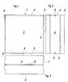
- Fig. 1 generally designates a plan element which has two opposing flat side surfaces 2 and 3, two opposing bearing surfaces 4 and 5 and two opposing butt joint surfaces 6 and 7.
- the plane elements 1 are provided with grooves 8 and 9 which only extend over a fraction of the width of the bearing joint surfaces 4, 5 and which have a constant cross section over their entire length.
- the grooves 8 each form the upper grooves of a lower plan element, while the grooves 9 form the respective lower grooves of an upper or so-called rising plan element.
- 4 to 7 show details of the grooves and the fitting pieces used for aligning the plan elements 1.
- the respective lower plan element is designated 1 and the respective upper plan element 1 '.
- the lower grooves 9 of the respective upper plan elements have parallel guide surfaces 11 and 12 running to the groove base 10.
- the adapters have opposite parallel end faces 22 and 23, of which at least sections are supported against the guide surfaces 11 and 12 of the grooves 9 or the guide surfaces 24 and 25 of the grooves 8.
- the fit pieces 15, 16 and 17 are circular. Due to the circular shape, as indicated in FIG. 7, they push aside thin-bed mortar 26 that has penetrated into the upper groove of the planar element 1.
- the depth T of the lower grooves 9 of the plan elements 1 ' is greater than the depth t of the upper grooves 8 of the plan elements 1, and the sum of the depths T + t is greater than the diameter D of the fitting pieces 15, 16 and 17.
- the diameter D the fitting pieces 15, 16 and 17 must be at least large enough that parallel end face sections of the fitting pieces protrude between the guide surfaces 11, 12 and 24, 25 of the grooves 8 and 9, respectively.
- the maximum Width b of the fitting pieces 15, 16, 17 is approximately 0.1 to 0.3 mm smaller than the distance A between the side surfaces of the grooves 8 and 9 forming the guide surfaces 11, 12 and 24.25.
- the fittings are preferably made of plastic. They can be injection molded, but it is also possible to cut them from a bar or tube. As the figures show, it is possible to design the fitments as solid bodies or as annular bodies.
Landscapes
- Engineering & Computer Science (AREA)
- Architecture (AREA)
- Physics & Mathematics (AREA)
- Electromagnetism (AREA)
- Civil Engineering (AREA)
- Structural Engineering (AREA)
- Toys (AREA)
- Finishing Walls (AREA)
- Piezo-Electric Or Mechanical Vibrators, Or Delay Or Filter Circuits (AREA)
- Inorganic Insulating Materials (AREA)
- Led Devices (AREA)
- Invalid Beds And Related Equipment (AREA)
- Impact Printers (AREA)
- Table Devices Or Equipment (AREA)
- Particle Accelerators (AREA)
- Joining Of Building Structures In Genera (AREA)
- Connection Of Plates (AREA)
Priority Applications (1)
| Application Number | Priority Date | Filing Date | Title |
|---|---|---|---|
| AT87730015T ATE82348T1 (de) | 1986-02-14 | 1987-02-13 | Planelement-verbund. |
Applications Claiming Priority (2)
| Application Number | Priority Date | Filing Date | Title |
|---|---|---|---|
| DE19863605166 DE3605166A1 (de) | 1986-02-14 | 1986-02-14 | Planelement-verbund |
| DE3605166 | 1986-02-14 |
Publications (3)
| Publication Number | Publication Date |
|---|---|
| EP0233835A2 EP0233835A2 (de) | 1987-08-26 |
| EP0233835A3 EP0233835A3 (en) | 1989-10-04 |
| EP0233835B1 true EP0233835B1 (de) | 1992-11-11 |
Family
ID=6294383
Family Applications (1)
| Application Number | Title | Priority Date | Filing Date |
|---|---|---|---|
| EP87730015A Expired - Lifetime EP0233835B1 (de) | 1986-02-14 | 1987-02-13 | Planelement-Verbund |
Country Status (4)
| Country | Link |
|---|---|
| EP (1) | EP0233835B1 (enExample) |
| AT (1) | ATE82348T1 (enExample) |
| DD (1) | DD253444A5 (enExample) |
| DE (2) | DE3605166A1 (enExample) |
Families Citing this family (5)
| Publication number | Priority date | Publication date | Assignee | Title |
|---|---|---|---|---|
| DE4120853A1 (de) * | 1990-06-26 | 1992-01-02 | Ver Sueddeutscher Kalksand | Verbund von bauelementen |
| FR2663661B1 (fr) * | 1990-06-26 | 1994-04-01 | Verein Suddeutscher Kalksandstei | Assemblage d'elements de construction. |
| DE19633593A1 (de) * | 1996-08-21 | 1998-02-26 | Bruno Lampka | Verfahren zum Aufmauern einer Kachelwand und bei diesem verwendete Einlagekörper |
| DE19714193C2 (de) * | 1997-04-07 | 2000-03-23 | Bosch Gmbh Robert | Vorrichtung zum Befestigen von Bauelementen |
| DE10255335A1 (de) * | 2002-11-27 | 2004-06-17 | Zipp House Gmbh | Aus einzelnen Baumodulen aufgebautes Gebäude |
Family Cites Families (6)
| Publication number | Priority date | Publication date | Assignee | Title |
|---|---|---|---|---|
| DE1664438U (enExample) * | ||||
| DE221810C (enExample) * | ||||
| US1106584A (en) * | 1913-07-26 | 1914-08-11 | Harry G Robbins | Wall construction. |
| DE2739017A1 (de) * | 1977-08-30 | 1979-03-08 | Michele Montanelli | Mauer sowie mauerelemente mit bloecken |
| US4514949A (en) * | 1983-05-06 | 1985-05-07 | Crespo Jorge L N | Interlocking system for building walls |
| NL8303223A (nl) * | 1983-09-19 | 1984-08-01 | Roelfsema Kalkzandsteenfab | Wand. |
-
1986
- 1986-02-14 DE DE19863605166 patent/DE3605166A1/de active Granted
-
1987
- 1987-02-13 AT AT87730015T patent/ATE82348T1/de not_active IP Right Cessation
- 1987-02-13 EP EP87730015A patent/EP0233835B1/de not_active Expired - Lifetime
- 1987-02-13 DE DE8787730015T patent/DE3782509D1/de not_active Expired - Fee Related
- 1987-02-16 DD DD87299940A patent/DD253444A5/de unknown
Also Published As
| Publication number | Publication date |
|---|---|
| DE3605166A1 (de) | 1987-08-27 |
| DE3782509D1 (de) | 1992-12-17 |
| DE3605166C2 (enExample) | 1990-02-15 |
| EP0233835A2 (de) | 1987-08-26 |
| ATE82348T1 (de) | 1992-11-15 |
| EP0233835A3 (en) | 1989-10-04 |
| DD253444A5 (de) | 1988-01-20 |
Similar Documents
| Publication | Publication Date | Title |
|---|---|---|
| DE29924260U1 (de) | Arretierungssystem und Bodenpaneel | |
| DE2626907A1 (de) | Kupplung fuer optische fasern | |
| DE3431462A1 (de) | Kreuzschlitten-linearlager-baugruppe | |
| DE1784533B2 (de) | Verbindung eines stabs mit einem vierkantrohr | |
| EP0233835B1 (de) | Planelement-Verbund | |
| DE2646020A1 (de) | Bauteilsatz zur herstellung von kastenmauern | |
| DE19920488A1 (de) | Längsverbinder zur Verbindung von Profilstäben | |
| DE3221866A1 (de) | Abstandshalter | |
| DE8809540U1 (de) | Abstandshalter | |
| DE9200496U1 (de) | Schalung für zylindrische Betonelemente | |
| DE4212786A1 (de) | Schienenanordnung | |
| DE60012484T2 (de) | Plattiertes Stahlrohr | |
| DE8604340U1 (de) | Planelement-Verbund | |
| DE2656481A1 (de) | Unterlegscheibe | |
| EP0341346A2 (de) | Betonabstandshalter | |
| DE2539356A1 (de) | Zargenprofil, insbesondere fuer feuerschutztueren | |
| DE2319211A1 (de) | Kunststoffrohr und verfahren zu dessen herstellung | |
| DE8614067U1 (de) | Dehnungsfugenleiste | |
| DE1912668A1 (de) | Bauelement zur Errichtung von Stuetzpfeilern,insbesondere im bergbaulichen Untertagebetrieb | |
| DE2030109A1 (de) | Fugendichtung für Bauteile | |
| DE1976776U (de) | Wandanschlussschiene fuer insbesondere flachdachabschlusskonstruktionen. | |
| DE20119042U1 (de) | Hohlkammerprofil für ein System für Präzisionsaufbauten | |
| DE19957069A1 (de) | Abstandhalter zur Festlegung der Fugenbreite zwischen Formsteinen | |
| DE202021103738U1 (de) | System zum Verbinden von Betonfertigteilen | |
| DE1559388A1 (de) | Stossverbindung von Wandplatten |
Legal Events
| Date | Code | Title | Description |
|---|---|---|---|
| PUAI | Public reference made under article 153(3) epc to a published international application that has entered the european phase |
Free format text: ORIGINAL CODE: 0009012 |
|
| AK | Designated contracting states |
Kind code of ref document: A2 Designated state(s): AT BE CH DE ES FR GB GR IT LI LU NL SE |
|
| PUAL | Search report despatched |
Free format text: ORIGINAL CODE: 0009013 |
|
| AK | Designated contracting states |
Kind code of ref document: A3 Designated state(s): AT BE CH DE ES FR GB GR IT LI LU NL SE |
|
| 17P | Request for examination filed |
Effective date: 19900131 |
|
| 17Q | First examination report despatched |
Effective date: 19910410 |
|
| GRAA | (expected) grant |
Free format text: ORIGINAL CODE: 0009210 |
|
| RAP1 | Party data changed (applicant data changed or rights of an application transferred) |
Owner name: HANIEL BAUSTOFF-INDUSTRIE KALKSANDSTEIN GMBH |
|
| AK | Designated contracting states |
Kind code of ref document: B1 Designated state(s): AT BE CH DE ES FR GB GR IT LI LU NL SE |
|
| PG25 | Lapsed in a contracting state [announced via postgrant information from national office to epo] |
Ref country code: IT Free format text: LAPSE BECAUSE OF FAILURE TO SUBMIT A TRANSLATION OF THE DESCRIPTION OR TO PAY THE FEE WITHIN THE PRE;WARNING: LAPSES OF ITALIAN PATENTS WITH EFFECTIVE DATE BEFORE 2007 MAY HAVE OCCURRED AT ANY TIME BEFORE 2007. THE CORRECT EFFECTIVE DATE MAY BE DIFFERENT FROM THE ONE RECORDED.SCRIBED TIME-LIMIT Effective date: 19921111 Ref country code: GB Effective date: 19921111 Ref country code: FR Effective date: 19921111 Ref country code: GR Free format text: LAPSE BECAUSE OF FAILURE TO SUBMIT A TRANSLATION OF THE DESCRIPTION OR TO PAY THE FEE WITHIN THE PRESCRIBED TIME-LIMIT Effective date: 19921111 |
|
| REF | Corresponds to: |
Ref document number: 82348 Country of ref document: AT Date of ref document: 19921115 Kind code of ref document: T |
|
| REF | Corresponds to: |
Ref document number: 3782509 Country of ref document: DE Date of ref document: 19921217 |
|
| PG25 | Lapsed in a contracting state [announced via postgrant information from national office to epo] |
Ref country code: ES Free format text: LAPSE BECAUSE OF FAILURE TO SUBMIT A TRANSLATION OF THE DESCRIPTION OR TO PAY THE FEE WITHIN THE PRESCRIBED TIME-LIMIT Effective date: 19930222 |
|
| PG25 | Lapsed in a contracting state [announced via postgrant information from national office to epo] |
Ref country code: LU Free format text: LAPSE BECAUSE OF NON-PAYMENT OF DUE FEES Effective date: 19930228 |
|
| EN | Fr: translation not filed | ||
| GBV | Gb: ep patent (uk) treated as always having been void in accordance with gb section 77(7)/1977 [no translation filed] |
Effective date: 19921111 |
|
| PLBE | No opposition filed within time limit |
Free format text: ORIGINAL CODE: 0009261 |
|
| STAA | Information on the status of an ep patent application or granted ep patent |
Free format text: STATUS: NO OPPOSITION FILED WITHIN TIME LIMIT |
|
| 26N | No opposition filed | ||
| PGFP | Annual fee paid to national office [announced via postgrant information from national office to epo] |
Ref country code: AT Payment date: 19940222 Year of fee payment: 8 |
|
| EAL | Se: european patent in force in sweden |
Ref document number: 87730015.2 |
|
| PG25 | Lapsed in a contracting state [announced via postgrant information from national office to epo] |
Ref country code: AT Effective date: 19950213 |
|
| PGFP | Annual fee paid to national office [announced via postgrant information from national office to epo] |
Ref country code: BE Payment date: 19960220 Year of fee payment: 10 Ref country code: SE Payment date: 19960220 Year of fee payment: 10 |
|
| PGFP | Annual fee paid to national office [announced via postgrant information from national office to epo] |
Ref country code: CH Payment date: 19960227 Year of fee payment: 10 |
|
| PGFP | Annual fee paid to national office [announced via postgrant information from national office to epo] |
Ref country code: NL Payment date: 19960228 Year of fee payment: 10 |
|
| PG25 | Lapsed in a contracting state [announced via postgrant information from national office to epo] |
Ref country code: SE Effective date: 19970214 |
|
| PG25 | Lapsed in a contracting state [announced via postgrant information from national office to epo] |
Ref country code: CH Effective date: 19970228 Ref country code: BE Effective date: 19970228 Ref country code: LI Effective date: 19970228 |
|
| BERE | Be: lapsed |
Owner name: HANIEL BAUSTOFF-INDUSTRIE KALKSANDSTEIN G.M.B.H. Effective date: 19970228 |
|
| PG25 | Lapsed in a contracting state [announced via postgrant information from national office to epo] |
Ref country code: NL Effective date: 19970901 |
|
| REG | Reference to a national code |
Ref country code: CH Ref legal event code: PL |
|
| EUG | Se: european patent has lapsed |
Ref document number: 87730015.2 |
|
| NLV4 | Nl: lapsed or anulled due to non-payment of the annual fee |
Effective date: 19970901 |
|
| PGFP | Annual fee paid to national office [announced via postgrant information from national office to epo] |
Ref country code: DE Payment date: 20030320 Year of fee payment: 17 |
|
| PG25 | Lapsed in a contracting state [announced via postgrant information from national office to epo] |
Ref country code: DE Free format text: LAPSE BECAUSE OF NON-PAYMENT OF DUE FEES Effective date: 20040901 |