EP0233835B1 - Plain element connection - Google Patents
Plain element connection Download PDFInfo
- Publication number
- EP0233835B1 EP0233835B1 EP87730015A EP87730015A EP0233835B1 EP 0233835 B1 EP0233835 B1 EP 0233835B1 EP 87730015 A EP87730015 A EP 87730015A EP 87730015 A EP87730015 A EP 87730015A EP 0233835 B1 EP0233835 B1 EP 0233835B1
- Authority
- EP
- European Patent Office
- Prior art keywords
- grooves
- plane
- plane elements
- elements
- fitting shapes
- Prior art date
- Legal status (The legal status is an assumption and is not a legal conclusion. Google has not performed a legal analysis and makes no representation as to the accuracy of the status listed.)
- Expired - Lifetime
Links
Images


Classifications
-
- E—FIXED CONSTRUCTIONS
- E04—BUILDING
- E04B—GENERAL BUILDING CONSTRUCTIONS; WALLS, e.g. PARTITIONS; ROOFS; FLOORS; CEILINGS; INSULATION OR OTHER PROTECTION OF BUILDINGS
- E04B2/00—Walls, e.g. partitions, for buildings; Wall construction with regard to insulation; Connections specially adapted to walls
- E04B2/02—Walls, e.g. partitions, for buildings; Wall construction with regard to insulation; Connections specially adapted to walls built-up from layers of building elements
- E04B2/04—Walls having neither cavities between, nor in, the solid elements
- E04B2/06—Walls having neither cavities between, nor in, the solid elements using elements having specially-designed means for stabilising the position
- E04B2/08—Walls having neither cavities between, nor in, the solid elements using elements having specially-designed means for stabilising the position by interlocking of projections or inserts with indentations, e.g. of tongues, grooves, dovetails
-
- E—FIXED CONSTRUCTIONS
- E04—BUILDING
- E04B—GENERAL BUILDING CONSTRUCTIONS; WALLS, e.g. PARTITIONS; ROOFS; FLOORS; CEILINGS; INSULATION OR OTHER PROTECTION OF BUILDINGS
- E04B2/00—Walls, e.g. partitions, for buildings; Wall construction with regard to insulation; Connections specially adapted to walls
- E04B2/02—Walls, e.g. partitions, for buildings; Wall construction with regard to insulation; Connections specially adapted to walls built-up from layers of building elements
- E04B2002/0202—Details of connections
- E04B2002/0204—Non-undercut connections, e.g. tongue and groove connections
- E04B2002/0208—Non-undercut connections, e.g. tongue and groove connections of trapezoidal shape
-
- E—FIXED CONSTRUCTIONS
- E04—BUILDING
- E04B—GENERAL BUILDING CONSTRUCTIONS; WALLS, e.g. PARTITIONS; ROOFS; FLOORS; CEILINGS; INSULATION OR OTHER PROTECTION OF BUILDINGS
- E04B2/00—Walls, e.g. partitions, for buildings; Wall construction with regard to insulation; Connections specially adapted to walls
- E04B2/02—Walls, e.g. partitions, for buildings; Wall construction with regard to insulation; Connections specially adapted to walls built-up from layers of building elements
- E04B2002/0202—Details of connections
- E04B2002/0243—Separate connectors or inserts, e.g. pegs, pins or keys
Definitions
- the invention relates to a plan element assembly with plan elements and for aligning the same circular fitting pieces which engage in recesses of mutually facing bearing surface plan elements arranged one above the other, the recesses on the lower and upper bearing surface of the plan elements being formed by a constant cross-section, continuous grooves whose side surfaces have at least in the vicinity of the groove base parallel guide surfaces for opposing parallel end faces or at least end face sections of fitting pieces, the fitting pieces and grooves of the plan elements being provided with insertion guide surfaces tapering towards the groove base, which guide the insertion of the fitting pieces into the grooves of the plan elements facilitate.
- a plan element composite of the above type is known from SE-PS 2 21 810.
- fitting pieces are used which have to be pressed into the grooves serving to receive them, since their thickness is somewhat larger than the width of the grooves. Pressing in the fitting pieces not only represents an additional burden for the construction worker, but also complicates the assembly of the plan elements.
- a disadvantage of the known construction is the fact that the grooves in the lower and upper bearing surfaces of the plan elements have the same depth, since it leads to the fact that comparatively thick layers of mortar can impair the accuracy of adjustment because the immersion depth of the fittings in each lower, with Inserts provided grooves of the plan elements leaves something to be desired. The risk of an unsatisfactory alignment of the plan elements increases if the outer diameters of the fitting pieces are kept within reasonable limits for reasons of economy of manufacture and for reasons of stability.
- the invention has for its object to provide a plan element composite of the type mentioned, the fit pieces ensure precise alignment of the plan elements despite the simplest shape.
- This object is achieved in that the slidably guided disc-shaped or annular fittings are provided on their outer edges with circumferential insertion guide surfaces and the depth of the lower grooves of the plan elements is greater than the depth of the upper grooves of the plan elements.
- the plan element assembly according to the invention offers the advantage that its simply shaped, easy-to-handle fittings make it possible to align the plan elements quickly and precisely regardless of the thickness of the mortar bed.
- the perfect fit of the fittings in the upper, i.e. Less deep grooves can be checked by visual inspection, while a perfect fit in the respective lower grooves is guaranteed due to the larger protrusion of the fitting pieces over the upper bearing joint surfaces compared to the depth of penetration in the upper grooves.
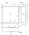
- Fig. 1 generally designates a plan element which has two opposing flat side surfaces 2 and 3, two opposing bearing surfaces 4 and 5 and two opposing butt joint surfaces 6 and 7.
- the plane elements 1 are provided with grooves 8 and 9 which only extend over a fraction of the width of the bearing joint surfaces 4, 5 and which have a constant cross section over their entire length.
- the grooves 8 each form the upper grooves of a lower plan element, while the grooves 9 form the respective lower grooves of an upper or so-called rising plan element.
- 4 to 7 show details of the grooves and the fitting pieces used for aligning the plan elements 1.
- the respective lower plan element is designated 1 and the respective upper plan element 1 '.
- the lower grooves 9 of the respective upper plan elements have parallel guide surfaces 11 and 12 running to the groove base 10.
- the adapters have opposite parallel end faces 22 and 23, of which at least sections are supported against the guide surfaces 11 and 12 of the grooves 9 or the guide surfaces 24 and 25 of the grooves 8.
- the fit pieces 15, 16 and 17 are circular. Due to the circular shape, as indicated in FIG. 7, they push aside thin-bed mortar 26 that has penetrated into the upper groove of the planar element 1.
- the depth T of the lower grooves 9 of the plan elements 1 ' is greater than the depth t of the upper grooves 8 of the plan elements 1, and the sum of the depths T + t is greater than the diameter D of the fitting pieces 15, 16 and 17.
- the diameter D the fitting pieces 15, 16 and 17 must be at least large enough that parallel end face sections of the fitting pieces protrude between the guide surfaces 11, 12 and 24, 25 of the grooves 8 and 9, respectively.
- the maximum Width b of the fitting pieces 15, 16, 17 is approximately 0.1 to 0.3 mm smaller than the distance A between the side surfaces of the grooves 8 and 9 forming the guide surfaces 11, 12 and 24.25.
- the fittings are preferably made of plastic. They can be injection molded, but it is also possible to cut them from a bar or tube. As the figures show, it is possible to design the fitments as solid bodies or as annular bodies.
Abstract
Description
Die Erfindung betrifft ein Planelement-Verbund mit Planelementen und zum Ausrichten derselben dienenden kreisrunden Paßformstücken, die in Ausnehmungen einander zugewandter Lagerfugenflächen jeweils übereinander angeordneter Planelemente greifen, wobei die Ausnehmungen an den jeweils unteren und oberen Lagerfugenflächen der Planelemente von einen konstanten Querschnitt aufweisenden, durchgehenden Nuten gebildet werden, deren Seitenflächen mindestens in der Nähe des Nutgrundes parallele Führungsflächen für sich gegenüberliegende parallele Stirnflächen oder zumindest Stirnflächenabschnitte von Paßformstücken aufweisen, wobei die Paßformstücke und Nuten der Planelemente mit sich zum Nutgrund verjüngenden Einschubleitflächen versehen sind, die das Einführen der Paßformstücke in die Nuten der Planelemente erleichtern.The invention relates to a plan element assembly with plan elements and for aligning the same circular fitting pieces which engage in recesses of mutually facing bearing surface plan elements arranged one above the other, the recesses on the lower and upper bearing surface of the plan elements being formed by a constant cross-section, continuous grooves whose side surfaces have at least in the vicinity of the groove base parallel guide surfaces for opposing parallel end faces or at least end face sections of fitting pieces, the fitting pieces and grooves of the plan elements being provided with insertion guide surfaces tapering towards the groove base, which guide the insertion of the fitting pieces into the grooves of the plan elements facilitate.
Ein Planelement-Verbund der vorstehenden Art ist aus der SE-PS 2 21 810 bekannt. Bei dem bekannten Planelement-Verbund werden Paßformstücke verwendet, die in zu ihrer Aufnahme dienende Nuten eingepreßt werden müssen, da ihre Dicke etwas größer als die Breite der Nuten ist. Das Einpressen der Paßformstücke stellt nicht nur eine zusätzliche Belastung für den Bauhandwerker dar, sondern es erschwert auch das Zusammenfügen der Planelemente. Als nachteilig erweist sich bei der bekannten Konstruktion außerdem der Umstand, daß die Nuten in den unteren und oberen Lagerfugenflächen der Planelemente die gleiche Tiefe haben, führt er doch dazu, daß vergleichsweise starke Mörtelschichten die Justiergenauigkeit beeinträchtigen können, weil die Eintauchtiefe der Paßformstücke in die jeweils unteren, mit Einschubflächen versehenen Nuten der Planelemente zu wünschen übrig läßt. Das Risiko einer nicht befriedigenden Ausrichtung der Planelemente nimmt dabei zu, wenn man die Außendurchmesser der Paßformstücke aus Gründen der Wirtschaftlichkeit ihrer Herstellung und aus Gründen der Stabilität in vertretbaren Grenzen hält.A plan element composite of the above type is known from SE-
Der Erfindung liegt die Aufgabe zugrunde, einen Planelement-Verbund der eingangs genannten Gattung zu schaffen, dessen Paßformstücke trotz einfachster Form ein genaues Ausrichten der Planelemente sicherstellen. Diese Aufgabe wird erfindungsgemäß dadurch gelöst, daß die in den Nuten verschiebbar geführten scheiben- oder ringförmigen Paßformstücke an ihren Außenrändern mit umlaufenden Einschubleitflächen versehen sind und die Tiefe der unteren Nuten der Planelemente größer ist als die Tiefe der oberen Nuten der Planelemente.The invention has for its object to provide a plan element composite of the type mentioned, the fit pieces ensure precise alignment of the plan elements despite the simplest shape. This object is achieved in that the slidably guided disc-shaped or annular fittings are provided on their outer edges with circumferential insertion guide surfaces and the depth of the lower grooves of the plan elements is greater than the depth of the upper grooves of the plan elements.
Der erfindungsgemäße Planelement-Verbund bietet den Vorteil, daß seine einfach geformten, leicht handhabbaren Paßformstücke unabhängig von der Dicke des Mörtelbettes ein schnelles und genaues Ausrichten der Planelemente ermöglichen. Der einwandfreie Sitz der Paßformstücke in den jeweils oberen, d.h. weniger tiefen Nuten kann durch Sichtkontrolle überprüft werden, während der einwandfreie Sitz in den jeweils unteren Nuten aufgrund des gegenüber der Eindringtiefe in den oberen Nuten größeren Überstandes der Paßformstücke über die oberen Lagerfugenflächen gewährleistet ist.The plan element assembly according to the invention offers the advantage that its simply shaped, easy-to-handle fittings make it possible to align the plan elements quickly and precisely regardless of the thickness of the mortar bed. The perfect fit of the fittings in the upper, i.e. Less deep grooves can be checked by visual inspection, while a perfect fit in the respective lower grooves is guaranteed due to the larger protrusion of the fitting pieces over the upper bearing joint surfaces compared to the depth of penetration in the upper grooves.
Weitere Einzelheiten und Merkmale der Erfindung ergeben sich aus den Unteransprüchen und der nachfolgenden Beschreibung der in der Zeichnung dargestellten Ausführungsbeispiele. Es zeigt
- Fig. 1
- die Seitenansicht eines Planelementes;
- Fig. 2
- die Ansicht einer Stoßfugenfläche des Planelementes gemäß Fig. 1;
- Fig. 3
- die Ansicht einer Lagerfugenfläche des Planelementes gemäß Fig. 1
- Fig. 4
- wiederum in vergrößertem Maßstab Teile zweier übereinander angeordneter Planelemente vor dem Ausrichten;
- Fig. 5
- die Teile der Planelemente gemäß Fig. 4 nach dem Ausrichten;
- Fig. 6
- Teile zweier durch ein anderes Paßformstück ausgerichteter Planelemente und
- Fig. 7
- einen Schnitt längs der Linie VIII-VIII in Fig. 6
- Fig. 1
- the side view of a plan element;
- Fig. 2
- the view of a butt joint surface of the plan element according to FIG. 1;
- Fig. 3
- the view of a bed joint surface of the plan element according to FIG. 1
- Fig. 4
- again on an enlarged scale, parts of two plan elements arranged one above the other before alignment;
- Fig. 5
- the parts of the plan elements according to Figure 4 after alignment.
- Fig. 6
- Parts of two plan elements aligned by another fitting and
- Fig. 7
- a section along the line VIII-VIII in Fig. 6
In Fig. 1 ist mit 1 allgemein ein Planelement bezeichnet, welches zwei sich gegenüberliegende plane Seitenflächen 2 und 3, zwei sich gegenüberliegende Lagerflächen 4 und 5 sowie zwei sich gegenüberliegende Stoßfugenflächen 6 und 7 aufweist. Im Bereich der Lagerfugenflächen 4 und 5 sind die Planelemente 1 mit sich lediglich über einen Bruchteil der Breite der Lagerfugenflächen 4,5 erstreckenden Nuten 8 und 9 versehen, die über ihre gesamte Länge einen konstanten Querschnitt haben. Die Nuten 8 bilden dabei die jeweils oberen Nuten eines unteren Planelementes, während die Nuten 9 die jeweils unteren Nuten eines oberen oder auch sogenannten aufgehenden Planelementes formen. Einzelheiten der Nuten und der zum Ausrichten zusammenzufügender Planelemente 1 dienenden Paßformstücke zeigen die Fig. 4 bis 7. In diesen Figuren ist das jeweils untere Planelement mit 1 und das jeweils obere Planelement mit 1' bezeichnet.In Fig. 1, 1 generally designates a plan element which has two opposing
Die unteren Nuten 9 der jeweils oberen Planelemente weisen zum Nutgrund 10 verlaufende parallele Führungsflächen 11 und 12 auf. An die Führungsflächen 11 und 12 schließen sich Einschubleitflächen 13 und 14 für Paßformstücke 15 bzw. 16 bzw. 17 an. Die Paßstücke besitzen sich gegenüberliegende parallele Stirnflächen 22 und 23, von denen sich mindestens Abschnitte gegen die Führungsflächen 11 und 12 der Nuten 9 bzw. die Führungsflächen 24 und 25 der Nuten 8 abstützen.The
Die Paßformstücke 15, 16 und 17 sind kreisrund. Aufgrund der kreisrunden Form drücken sie, wie in Fig. 7 angedeutet, in die obere Nut des Planelementes 1 eingedrungenen Dünnbettmörtel 26 beiseite.The
Die Tiefe T der unteren Nuten 9 der Planelemente 1' ist größer als die Tiefe t der oberen Nuten 8 der Planelemente 1, und die Summe der Tiefen T + t ist größer als der Durchmesser D der Paßformstücke 15, 16 und 17. Der Durchmesser D der Paßformstücke 15, 16 und 17 muß mindestens so groß sein, daß parallele Stirnflächenabschnitte der Paßformstücke zwischen die Führungsflächen 11,12 bzw. 24,25 der Nuten 8 bzw. 9 ragen. In der Praxis ist die maximale Breite b der Paßformstücke 15,16,17 etwa 0,1 bis 0,3 mm kleiner als der Abstand A zwischen den die Führungsflächen 11,12 bzw. 24,25 bildenden Seitenflächen der Nuten 8 bzw. 9.The depth T of the
Die Paßformstücke bestehen vorzugsweise aus Kunststoff. Sie können im Spritzgußverfahren hergestellt werden, es ist jedoch auch möglich, sie von einer Stange oder einem Rohr abzuschneiden. Wie die Figuren zeigen, ist sowohl eine Ausbildung der Paßformstücke als Vollkörper als auch als Ringkörper möglich.The fittings are preferably made of plastic. They can be injection molded, but it is also possible to cut them from a bar or tube. As the figures show, it is possible to design the fitments as solid bodies or as annular bodies.
Claims (4)
- Plane element connection having plane elements (1) and circular fitting shapes (15, 16, 17) which serve for aligning said plane elements and engage in recesses of mutually facing bed joint surfaces (4, 5) of plane elements (1) arranged one above the other in each case, the recesses on the respective lower and upper bed joint surfaces (5) of the plane elements (1) being formed by continuous grooves (8, 9) which have a constant crosssection and whose side surfaces have parallel guide surfaces (11, 12), at least in the vicinity of the groove base, for parallel end faces (22, 23) located opposite one another or at least end-face portions of fitting shapes (16, 17, 18), the fitting shapes (16, 17, 18) and the grooves (9) of the plane elements (1) being provided with insertion guide surfaces (13, 14) which taper towards the groove base and facilitate the introduction of the fitting shapes (16, 17, 18) into the grooves (9) of the plane elements (1), characterised in that the disc-shaped or annular fitting shapes (15, 16, 17), which are guided displaceably in the grooves (8, 9), are provided on their outer edges with circumferential insertion guide surfaces (18, 19; 20, 21), and the depth (T) of the lower grooves (9) of the plane elements (1') is greater than the depth (t) of the upper grooves (8) of the plane elements (1).
- Plane element connection according to Claim 1, characterised in that the maximum width (b) of the fitting shapes (15, 16, 17) is approximately 0.1 to 0.3 mm smaller than the spacing (A) between the parallel side surfaces (11, 12; 24, 25) or side surface portions of the grooves (8, 9).
- Plane element connection according to Claim 1 or 2, characterised in that only the lower grooves (9) of the plane elements (1, 1') are provided with insertion guide surfaces (13, 14).
- Plane element connection according to one of Claims 1 to 3, characterised in that the fitting shapes (15, 16, 17) are composed of plastic.
Priority Applications (1)
| Application Number | Priority Date | Filing Date | Title |
|---|---|---|---|
| AT87730015T ATE82348T1 (en) | 1986-02-14 | 1987-02-13 | PLAN ELEMENT COMPOSITION. |
Applications Claiming Priority (2)
| Application Number | Priority Date | Filing Date | Title |
|---|---|---|---|
| DE3605166 | 1986-02-14 | ||
| DE19863605166 DE3605166A1 (en) | 1986-02-14 | 1986-02-14 | PLANELEMENT COMPOSITE |
Publications (3)
| Publication Number | Publication Date |
|---|---|
| EP0233835A2 EP0233835A2 (en) | 1987-08-26 |
| EP0233835A3 EP0233835A3 (en) | 1989-10-04 |
| EP0233835B1 true EP0233835B1 (en) | 1992-11-11 |
Family
ID=6294383
Family Applications (1)
| Application Number | Title | Priority Date | Filing Date |
|---|---|---|---|
| EP87730015A Expired - Lifetime EP0233835B1 (en) | 1986-02-14 | 1987-02-13 | Plain element connection |
Country Status (4)
| Country | Link |
|---|---|
| EP (1) | EP0233835B1 (en) |
| AT (1) | ATE82348T1 (en) |
| DD (1) | DD253444A5 (en) |
| DE (2) | DE3605166A1 (en) |
Families Citing this family (5)
| Publication number | Priority date | Publication date | Assignee | Title |
|---|---|---|---|---|
| DE4120853A1 (en) * | 1990-06-26 | 1992-01-02 | Ver Sueddeutscher Kalksand | Union between stone blocks for building wall - involves grooves on one horizontal face side of each block to accommodate two-armed slide |
| NL9101109A (en) * | 1990-06-26 | 1992-01-16 | Ver Sueddeutscher Kalksand | CONNECTED COLLECTION OF BUILDING ELEMENTS. |
| DE19633593A1 (en) * | 1996-08-21 | 1998-02-26 | Bruno Lampka | Tiled wall completion for plate and body tile designs |
| DE19714193C2 (en) * | 1997-04-07 | 2000-03-23 | Bosch Gmbh Robert | Device for fastening components |
| DE10255335A1 (en) * | 2002-11-27 | 2004-06-17 | Zipp House Gmbh | Building constructed from individual building modules |
Family Cites Families (6)
| Publication number | Priority date | Publication date | Assignee | Title |
|---|---|---|---|---|
| DE1664438U (en) * | ||||
| DE221810C (en) * | ||||
| US1106584A (en) * | 1913-07-26 | 1914-08-11 | Harry G Robbins | Wall construction. |
| DE2739017A1 (en) * | 1977-08-30 | 1979-03-08 | Michele Montanelli | Interlocking wall building blocks - have lengthways grooves engaged by base panel rib or narrow strips between rows |
| US4514949A (en) * | 1983-05-06 | 1985-05-07 | Crespo Jorge L N | Interlocking system for building walls |
| NL8303223A (en) * | 1983-09-19 | 1984-08-01 | Roelfsema Kalkzandsteenfab | WALL. |
-
1986
- 1986-02-14 DE DE19863605166 patent/DE3605166A1/en active Granted
-
1987
- 1987-02-13 EP EP87730015A patent/EP0233835B1/en not_active Expired - Lifetime
- 1987-02-13 AT AT87730015T patent/ATE82348T1/en not_active IP Right Cessation
- 1987-02-13 DE DE8787730015T patent/DE3782509D1/en not_active Expired - Fee Related
- 1987-02-16 DD DD87299940A patent/DD253444A5/en unknown
Also Published As
| Publication number | Publication date |
|---|---|
| EP0233835A3 (en) | 1989-10-04 |
| DE3782509D1 (en) | 1992-12-17 |
| EP0233835A2 (en) | 1987-08-26 |
| ATE82348T1 (en) | 1992-11-15 |
| DD253444A5 (en) | 1988-01-20 |
| DE3605166C2 (en) | 1990-02-15 |
| DE3605166A1 (en) | 1987-08-27 |
Similar Documents
| Publication | Publication Date | Title |
|---|---|---|
| DE3141807C1 (en) | Component with a rectangular plate, for example a panel or sign | |
| DE2626907A1 (en) | COUPLING FOR OPTICAL FIBERS | |
| DE3406722A1 (en) | MULTI-PIECE THERMAL INSULATED METAL PROFILE FOR FACADE OR ROOF CONSTRUCTIONS | |
| DE1784533B2 (en) | CONNECTING A ROD TO A SQUARE TUBE | |
| DE2826032A1 (en) | MOUNTING DEVICE FOR LIGHT GUIDE CABLE | |
| EP0233835B1 (en) | Plain element connection | |
| DE2646020A1 (en) | Prefabricated concrete building components - are used for making composite walls and concrete foundations | |
| DE3221866A1 (en) | Spacer | |
| DE19920488A1 (en) | Longitudinal connector for connecting profiled rods is plate-shaped element with holes or milled area along bending line to produce required angle | |
| DE3241424A1 (en) | CONNECTING DEVICE | |
| CH682341A5 (en) | Connector for joining two corner profile rails - involves insertion of connector in hollow space of rails which aligns two ends exactly with each other | |
| DE4212786A1 (en) | Rail arrangement for permanent way - has intermediate layer with flexible section between rail foot and ribbed base plate | |
| DE60012484T2 (en) | Clad steel pipe | |
| EP0341346A2 (en) | Concrete reinforcement spacer | |
| DE2539356A1 (en) | Fire screen door case metal shaped unit - has separated section joined by narrow connectors to prevent heat transfer | |
| DE2319211A1 (en) | PLASTIC PIPE AND METHOD FOR MANUFACTURING IT | |
| DE8614067U1 (en) | Expansion joint strip | |
| DE1912668A1 (en) | Construction element for the erection of supporting pillars, especially in underground mining | |
| DE2030109A1 (en) | Joint sealing for components | |
| AT371524B (en) | REINFORCEMENT ELEMENT AND METHOD FOR LAYING IT | |
| DE202018104679U1 (en) | furniture | |
| DE202021103738U1 (en) | System for connecting precast concrete parts | |
| DE1976776U (en) | WALL CONNECTION RAIL FOR FLAT ROOF END CONSTRUCTIONS IN PARTICULAR. | |
| DE102018130981A1 (en) | Profile rail of a linear guide | |
| DE1559388A1 (en) | Butt joint of wall panels |
Legal Events
| Date | Code | Title | Description |
|---|---|---|---|
| PUAI | Public reference made under article 153(3) epc to a published international application that has entered the european phase |
Free format text: ORIGINAL CODE: 0009012 |
|
| AK | Designated contracting states |
Kind code of ref document: A2 Designated state(s): AT BE CH DE ES FR GB GR IT LI LU NL SE |
|
| PUAL | Search report despatched |
Free format text: ORIGINAL CODE: 0009013 |
|
| AK | Designated contracting states |
Kind code of ref document: A3 Designated state(s): AT BE CH DE ES FR GB GR IT LI LU NL SE |
|
| 17P | Request for examination filed |
Effective date: 19900131 |
|
| 17Q | First examination report despatched |
Effective date: 19910410 |
|
| GRAA | (expected) grant |
Free format text: ORIGINAL CODE: 0009210 |
|
| RAP1 | Party data changed (applicant data changed or rights of an application transferred) |
Owner name: HANIEL BAUSTOFF-INDUSTRIE KALKSANDSTEIN GMBH |
|
| AK | Designated contracting states |
Kind code of ref document: B1 Designated state(s): AT BE CH DE ES FR GB GR IT LI LU NL SE |
|
| PG25 | Lapsed in a contracting state [announced via postgrant information from national office to epo] |
Ref country code: IT Free format text: LAPSE BECAUSE OF FAILURE TO SUBMIT A TRANSLATION OF THE DESCRIPTION OR TO PAY THE FEE WITHIN THE PRE;WARNING: LAPSES OF ITALIAN PATENTS WITH EFFECTIVE DATE BEFORE 2007 MAY HAVE OCCURRED AT ANY TIME BEFORE 2007. THE CORRECT EFFECTIVE DATE MAY BE DIFFERENT FROM THE ONE RECORDED.SCRIBED TIME-LIMIT Effective date: 19921111 Ref country code: GB Effective date: 19921111 Ref country code: FR Effective date: 19921111 Ref country code: GR Free format text: LAPSE BECAUSE OF FAILURE TO SUBMIT A TRANSLATION OF THE DESCRIPTION OR TO PAY THE FEE WITHIN THE PRESCRIBED TIME-LIMIT Effective date: 19921111 |
|
| REF | Corresponds to: |
Ref document number: 82348 Country of ref document: AT Date of ref document: 19921115 Kind code of ref document: T |
|
| REF | Corresponds to: |
Ref document number: 3782509 Country of ref document: DE Date of ref document: 19921217 |
|
| PG25 | Lapsed in a contracting state [announced via postgrant information from national office to epo] |
Ref country code: ES Free format text: LAPSE BECAUSE OF FAILURE TO SUBMIT A TRANSLATION OF THE DESCRIPTION OR TO PAY THE FEE WITHIN THE PRESCRIBED TIME-LIMIT Effective date: 19930222 |
|
| PG25 | Lapsed in a contracting state [announced via postgrant information from national office to epo] |
Ref country code: LU Free format text: LAPSE BECAUSE OF NON-PAYMENT OF DUE FEES Effective date: 19930228 |
|
| EN | Fr: translation not filed | ||
| GBV | Gb: ep patent (uk) treated as always having been void in accordance with gb section 77(7)/1977 [no translation filed] |
Effective date: 19921111 |
|
| PLBE | No opposition filed within time limit |
Free format text: ORIGINAL CODE: 0009261 |
|
| STAA | Information on the status of an ep patent application or granted ep patent |
Free format text: STATUS: NO OPPOSITION FILED WITHIN TIME LIMIT |
|
| 26N | No opposition filed | ||
| PGFP | Annual fee paid to national office [announced via postgrant information from national office to epo] |
Ref country code: AT Payment date: 19940222 Year of fee payment: 8 |
|
| EAL | Se: european patent in force in sweden |
Ref document number: 87730015.2 |
|
| PG25 | Lapsed in a contracting state [announced via postgrant information from national office to epo] |
Ref country code: AT Effective date: 19950213 |
|
| PGFP | Annual fee paid to national office [announced via postgrant information from national office to epo] |
Ref country code: BE Payment date: 19960220 Year of fee payment: 10 Ref country code: SE Payment date: 19960220 Year of fee payment: 10 |
|
| PGFP | Annual fee paid to national office [announced via postgrant information from national office to epo] |
Ref country code: CH Payment date: 19960227 Year of fee payment: 10 |
|
| PGFP | Annual fee paid to national office [announced via postgrant information from national office to epo] |
Ref country code: NL Payment date: 19960228 Year of fee payment: 10 |
|
| PG25 | Lapsed in a contracting state [announced via postgrant information from national office to epo] |
Ref country code: SE Effective date: 19970214 |
|
| PG25 | Lapsed in a contracting state [announced via postgrant information from national office to epo] |
Ref country code: CH Effective date: 19970228 Ref country code: BE Effective date: 19970228 Ref country code: LI Effective date: 19970228 |
|
| BERE | Be: lapsed |
Owner name: HANIEL BAUSTOFF-INDUSTRIE KALKSANDSTEIN G.M.B.H. Effective date: 19970228 |
|
| PG25 | Lapsed in a contracting state [announced via postgrant information from national office to epo] |
Ref country code: NL Effective date: 19970901 |
|
| REG | Reference to a national code |
Ref country code: CH Ref legal event code: PL |
|
| EUG | Se: european patent has lapsed |
Ref document number: 87730015.2 |
|
| NLV4 | Nl: lapsed or anulled due to non-payment of the annual fee |
Effective date: 19970901 |
|
| PGFP | Annual fee paid to national office [announced via postgrant information from national office to epo] |
Ref country code: DE Payment date: 20030320 Year of fee payment: 17 |
|
| PG25 | Lapsed in a contracting state [announced via postgrant information from national office to epo] |
Ref country code: DE Free format text: LAPSE BECAUSE OF NON-PAYMENT OF DUE FEES Effective date: 20040901 |