EP0230503A2 - Wellendichtung - Google Patents
Wellendichtung Download PDFInfo
- Publication number
- EP0230503A2 EP0230503A2 EP86105636A EP86105636A EP0230503A2 EP 0230503 A2 EP0230503 A2 EP 0230503A2 EP 86105636 A EP86105636 A EP 86105636A EP 86105636 A EP86105636 A EP 86105636A EP 0230503 A2 EP0230503 A2 EP 0230503A2
- Authority
- EP
- European Patent Office
- Prior art keywords
- sealing
- shaft
- shaft seal
- sealing element
- sealing surface
- Prior art date
- Legal status (The legal status is an assumption and is not a legal conclusion. Google has not performed a legal analysis and makes no representation as to the accuracy of the status listed.)
- Granted
Links
- 238000007789 sealing Methods 0.000 claims abstract description 68
- 239000000463 material Substances 0.000 claims abstract description 4
- 238000009434 installation Methods 0.000 description 2
- 238000004519 manufacturing process Methods 0.000 description 2
- 239000007769 metal material Substances 0.000 description 2
- OKTJSMMVPCPJKN-UHFFFAOYSA-N Carbon Chemical compound [C] OKTJSMMVPCPJKN-UHFFFAOYSA-N 0.000 description 1
- 230000015572 biosynthetic process Effects 0.000 description 1
- 229910052799 carbon Inorganic materials 0.000 description 1
- 230000000295 complement effect Effects 0.000 description 1
- 230000008021 deposition Effects 0.000 description 1
- 230000000694 effects Effects 0.000 description 1
- 230000005489 elastic deformation Effects 0.000 description 1
- 239000013013 elastic material Substances 0.000 description 1
- 239000000314 lubricant Substances 0.000 description 1
- 239000010687 lubricating oil Substances 0.000 description 1
- 238000005461 lubrication Methods 0.000 description 1
- 239000003921 oil Substances 0.000 description 1
- 239000004810 polytetrafluoroethylene Substances 0.000 description 1
- 229920001343 polytetrafluoroethylene Polymers 0.000 description 1
- 238000004073 vulcanization Methods 0.000 description 1
Images


Classifications
-
- F—MECHANICAL ENGINEERING; LIGHTING; HEATING; WEAPONS; BLASTING
- F16—ENGINEERING ELEMENTS AND UNITS; GENERAL MEASURES FOR PRODUCING AND MAINTAINING EFFECTIVE FUNCTIONING OF MACHINES OR INSTALLATIONS; THERMAL INSULATION IN GENERAL
- F16J—PISTONS; CYLINDERS; SEALINGS
- F16J15/00—Sealings
- F16J15/16—Sealings between relatively-moving surfaces
- F16J15/32—Sealings between relatively-moving surfaces with elastic sealings, e.g. O-rings
- F16J15/3204—Sealings between relatively-moving surfaces with elastic sealings, e.g. O-rings with at least one lip
-
- Y—GENERAL TAGGING OF NEW TECHNOLOGICAL DEVELOPMENTS; GENERAL TAGGING OF CROSS-SECTIONAL TECHNOLOGIES SPANNING OVER SEVERAL SECTIONS OF THE IPC; TECHNICAL SUBJECTS COVERED BY FORMER USPC CROSS-REFERENCE ART COLLECTIONS [XRACs] AND DIGESTS
- Y10—TECHNICAL SUBJECTS COVERED BY FORMER USPC
- Y10S—TECHNICAL SUBJECTS COVERED BY FORMER USPC CROSS-REFERENCE ART COLLECTIONS [XRACs] AND DIGESTS
- Y10S277/00—Seal for a joint or juncture
- Y10S277/935—Seal made of a particular material
- Y10S277/944—Elastomer or plastic
Definitions
- the invention relates to a shaft seal, comprising a sealing element made of polymeric material and with a sealing surface that contacts the shaft with an elastic contact area, wherein in the area of the contact zone formed in this way at least one integrally formed ring projection encompassing the shaft is provided.
- a shaft seal of the aforementioned type is known from US-PS 28 04 325.
- the sealing element used is made of PTFE and thus a material that is characterized by a horn-like, inelastic nature.
- the surface of the sealed shaft is only touched by the inwardly facing part of the ring projections arranged in a close axial succession on the sealing surface, which are separated from one another by deep grooves of a size and profile design similar to the ring projections. They can thus complement each other in their effectiveness, which gives the shaft seal an excellent effectiveness in the new, unused condition of the ring projections.
- the service life is still unsatisfactory due to the considerable wear of the ring projections.
- the invention has for its object to develop a shaft seal of the type mentioned in such a way that there is an improved service life.
- the annular projection of the sealing element of the shaft seal according to the invention is of extreme fineness and generally only has a height of 0.04 to 0.8 mm, expediently that of 0.05 to 0.09 mm with a comparatively short length in the axial direction.
- the normal pressing forces are sufficient and at the same time cause mutual contact between the sealing surface and the surface of the shaft to be sealed at a small axial distance from the ring projection.
- the wear occurring in this critical zone there is a significant improvement. Even with the sealing of lubricating oil, the deposition of oil carbon in the area of the lubricant pockets formed in this way, concentrically surrounding the shaft, was not observed.
- the sealing element is preferably made of rubber with a Shore A hardness of 70 to 80, and is characterized in particular in this case by a long service life.
- the sealing element can be pressed against the shaft by a spring element, for example by a helical spring, and in this case a design similar to the design according to DE-AS 1007130 is recommended, in which instead of the sealing lip provided there contacting the shaft with a shaft sealing edge, a sealing surface with the characterizing features of claim 1 is provided. It is also possible to limit the sealing surface in the axial direction by means of conical surfaces.
- the cone angle on the side facing the sealed space should be larger than the opposite cone angle and can be approximately 90-120 °.
- sealing surface has a profile which is axially curved and which only touches the shaft in the region of the end facing the sealed space.
- the curvature can be similar to that of the sealing element according to US-PS 28 04 325.
- the ring projection is expediently formed by a sealing lip, for example a sealing lip, which is formed by the intersection of two conical surfaces intersecting one another.
- the cone surface facing the medium to be sealed is provided with a larger cone angle than the opposite surface with a corresponding design.
- Useful values are in the range between 120 and 130 °.
- a plurality of ring projections which are at a mutual axial distance can be provided.
- the mutual distance in these cases is to be coordinated with the dimensions of the individual ring projections and the hardness of the rubber used for the production of the sealing element, so that there is mutual contact between the sealing surface and the shaft to be sealed under the operating pressure in the spaces between the individual ring projections .
- the shaft seal shown in FIG. 1 comprises the outer ring 1, 2 and the sealing element 3 fixed therein in a liquid-tight and non-rotatable manner.
- the latter is made of rubber with a Shore A hardness of 75 and is provided on the inside with a bulge projecting in the direction of the sealed space.
- the sealing surface is interrupted by a ring projection which is axially spaced from one another and concentrically surround the shaft and has a height of 0.06 mm.
- These ring projections are delimited on both sides in the axial direction by a conical surface which cuts through the sealing lip, the conical angle of the conical surface facing the outside air being 58 °, the conical angle of the conical surface facing the sealed medium being approximately 122 °.
- the resulting total extent of each ring projection in the axial direction is 0.14 mm, the mutual distance between the sealing lips of adjacent ring projections is about 0.4 mm.
- the manufacturing-related shape of the sealing surface is illustrated by FIG. 2, whereby for the sake of clarity, a true-to-scale representation has been omitted.
- FIG. 3 serves to illustrate the elastic deformation of the sealing surface of a shaft seal according to the invention that results when the associated shaft is installed. It can be clearly seen that the sealing surface 5 located between the ring projections 4 comes into contact with the surface of the shaft to be sealed under the effect of the pressing of the sealing element which is necessary for operation. In this case, too, the deformations were not reproduced to scale.
- the axial succession of the concentric annular grooves 6 of different profiles and microscopic dimensions favors the usage properties such that the shaft seal 9 can be used for demanding purposes.
- FIG. 4 refers to an embodiment which is based on that according to DE-AS 10 07 130 in its external shape.
- the embodiment according to the invention consists of a sealing element 3 made of rubber, which is adhesively fixed to the outer ring 1 made of metallic material by vulcanization.
- the sealing element 3 is not provided with a sealing lip abutting the shaft with sharp edges, but rather with a sealing surface modified in the manner according to the invention. This is pressed against the shaft by the ring coil spring 7 made of metallic material placed on the outer circumference of the sealing element 3.
- the ring projections 4 projecting inward from the sealing surface in the radial direction before the shaft seal is installed are thereby countersunk in the sealing surface.
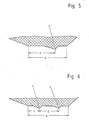
- FIGS. 5 and 6 Two exemplary design options for the formation of the sealing surface are shown in FIGS. 5 and 6. In the former case, there is only a single annular projection 4 in the area of the sealing surface, in the latter case there are two of them, the mutual, axial distance being denoted by D.
- the sealing surface B is limited on the side facing away from the sealed space by the line of action of the helical spring 7, as can be seen from FIG. 4. It has a length in the axial direction of 0.2 to 1.5 mm, advantageously that of 0.25 to 1.0 mm.
- the value A (FIG. 5) should correspond to approximately two thirds of the axial extent of the sealing surface B, the value C (FIG. 6) approximately to a quarter of the stated value and the value D approximately to half.
- the cone angle of the ring projection 4 facing the sealed space is approximately 2.5 times as large as the cone angle of the ring projection on the side facing the outside air.
- the rubber-elastic material forming the sealing element 3 has a Shore A hardness of approximately 80.
Landscapes
- Engineering & Computer Science (AREA)
- General Engineering & Computer Science (AREA)
- Mechanical Engineering (AREA)
- Sealing With Elastic Sealing Lips (AREA)
- Sealing Devices (AREA)
- Sealing Of Bearings (AREA)
- General Details Of Gearings (AREA)
- Devices For Conveying Motion By Means Of Endless Flexible Members (AREA)
- Organic Insulating Materials (AREA)
- Glass Compositions (AREA)
Abstract
Description
- Die Erfindung betrifft eine Wellendichtung, umfassend ein Dichtelement aus polymerem Werkstoff und mit einer Dichtfläche, die die Welle mit einer elastischen Anpressung flächenhaft berührt, wobei eim Bereich der so gebildeten Berührungszone wenigstens ein die Welle konzentrisch umschließender, einstückig angeformter Ringvorsprung vorgesehen ist.
- Eine Wellendichtung der vorgenannten Art ist aus der US-PS 28 04 325 bekannt. Das darin zur Anwendung gelangende Dichtelement besteht aus PTFE und damit einem Werkstoff, der durch eine hornähnliche, unelastische Beschaffenheit gekennzeichnet ist. Die Oberfläche der abgedichteten Welle wird nur von dem nach innen weisenden Teil der in einer engen axialen Aufeinanderfolge auf der Dichtfläche angeordneten Ringvorsprünge berührt, welche durch tiefe Nuten einer den Ringvorsprüngen ähnlichen Größe und Profilgestaltung voneinander getrennt sind. Sie vermögen dadurch einander in ihrer Wirksamkeit zu ergänzen, was der Wellendichtung im neuen, unverbrauchten Zustand der Ringvorsprünge eine ausgezeichnete Wirksamkeit verleiht. Die Gebrauchsdauer ist jedoch wegen des erheblichen Verschleißes der Ringvorsprünge noch wenig befriedigend.
- Der Erfindung liegt die Aufgabe zugrunde, eine Wellendichtung der eingangs genannten Art derart weiterzuentwickeln, daß sich eine verbesserte Gebrauchsdauer ergibt.
- Diese Aufgabe wird erfindungsgemäß bei einer Wellendichtung der eingangs genannten Art dadurch gelöst, daß das Dichtelement aus Gummi einer Härte Shore A von 65 bis 90 besteht und daß der Ringvorsprung durch die flächenhafte Anpressung des Dichtelementes an die Welle in die Dichtfläche versenkbar ist.
- Der Ringvorsprung des Dichtelementes der erfindungsgemäßen Wellendichtung ist von extremer Feinheit und weist im allgemeinen nur eine Höhe von 0,04 bis 0,8 mm auf, zweckmäßig eine solche von 0,05 bis 0,09 mm bei vergleichbar geringer Länge in axialer Richtung.
- Für das Versenken in dem weichelastis chen Gummikörper des Dichtelementes genügen dadurch die normalen Andrückkräfte und bewirken zugleich eine gegenseitige Berührung zwischen der Dichtfläche und der Oberfläche der abzudichtenden Welle in geringem axialen Abstand von dem Ringvorsprung. Die so erhaltenen, die Welle beiderseits des Ringvorsprunges konzentrisch umschließenden Hohlräume füllen sich unter normalen Betriebsbedingungen mit abzudichtendem Medium, wodurch eine gute Schmierung der dynamischen Abdichtungszone gewährleistet ist. Hinsichtlich des in dieser kritischen Zone auftretenden Verschleißes ergibt sich eine deutliche Verbesserung. Auch bei der Abdichtung von Schmieröl wurde die Ablagerung von Ölkohle im Bereich der so gebildeten, die Welle konzentrisch umschließenden Schmierstofftaschen nicht beobachtet.
- Das Dichtelement besteht bevorzugt aus Gummi einer Härte Shore A von 70 bis 80, und zeichnet sich insbesondere in diesem Falle durch eine große Gebrauchsdauer aus.
- Das Dichtelement kann durch ein Federlement an die Welle angepreßt sein, beispielsweise durch eine Ringwendelfeder, und in diesem Falle eimpfiehlt sich eine der Ausführung nach der DE-AS 1007130 ähnliche Gstaltung, bei der anstelle der dort vorgesehenen die Welle schaftkantig berührenden Dichtlippe eine Dichtfläche mit den kennzeichnenden Merkmalen des Patentanspruches 1 vorgesehen ist. Auch ist es möglich, die Dichtfläche in axialer Richtung durch Kegelflächen zu begrenzen.
- Der Kegelwinkel auf der dem abgedichteten Raum zugewandten Seite sollte in diesem Falle größer bemessen sein als der gegenüberliegende Kegelwinkel und kann etwa 90 - 120° betragen.
- Die Anwendung der Erfindung bei anders gestalteten Dichtelementen ist ebenfalls möglich und führt zu besonders guten Ergebnissen bei Ausführungen, bei denen die Dichtfläche ein Profil aufweist, das axial in sich gewölbt ist und das die Welle nur im Bereich des dem abgedichteten Raum zugewandten Endes berührt. Die Wölbung kann derjenigen des Dichtelementes nach der US-PS 28 04 325 ähnlich sein.
- Der Ringvorsprung wird zweckmäßig durch eine Dichtlippe gebildet, beispielsweise eine Dichtlippe, die durch die Schnittlinie zweier einander durchschneidender Kegelflächen gebildet wird. Die dem abzudichtenden Medium zugewandte Kegelfläche ist bei einer entsprechenden Ausbildung mit einem größeren Kegelwinkel versehen als die gegenüberliegende Fläche. Zweckmäßige Werte liegen im Bereich zwischen 120 und 130°.
- Im Bereich der Dichtfläche können mehrere, einen gegenseitigen axialen Abstand aufweisende Ringvorsprünge vorgesehen sein.
- Der gegenseitige Abstand ist in diesen Fällen so mit der Dimension der einzelnen Ringvorsprünge und der Härte des für die Herstellung des Dichtelementes verwendeten Gummis abzustimmen, daß sich unter der betriebsgedingten Anpressung in den Zwischenräumen der einzelnen Ringvorsprünge eine gegenseitige Berührung zwischen der Dichtfläche und der abzudichtenden Welle ergibt.
- Nur in diesem Falle wird die Entstehung von Anbackungserscheinungen im Bereich der dynamischen Abdichtungszone sicher vermieden und damit über lange Zeiträume ein zuverlässiges und weitgehend verschleißfreies Abdichtungsergebnis erzielt. Die Drehrichtung der abzudichtenden Welle ist dabei beliebig.
- Der Gegenstand der vorliegenden Erfindung wird nachfolgend anhand der als Anlage beigefügten Zeichnung weiter erläutert. Es zeigen:
- Figur 1 eine beispielhafte Ausführung der erfindungsgemäßen Wellendichtung in halbgeschnittener Darstellung nach dem Einbau.
- Figur 2 einen Ausschnitt eines in der erfindungsgemäßen Wellendichtung zur Anwendung gelangenden Dichtelementes im Bereich der Dichtfläche.
- Figur 3 den in Figur 2 gezeigten Bereich des Dichtelementes nach dem Einbau der zugehörigen Welle.
- Figur 4 eine andere Ausführung der erfindungsgemäßen Wellendichtung in halbgeschnittener Darstellung.
- Figuren 5 und 6
zwei voneinander verschied ene Auslegungen der Dichtfläche bei einer an Figur 4 angelehnten Gestaltung. - Die in Figur 1 gezeigte Wellendichtung umfaßt den Außenring 1,2 und das flüssigkeitsdicht und verdrehsicher darin festgelegte Dichtelement 3. Letzteres besteht aus Gummi einer Härte Shore A von 75 und ist innenseitig mit einer in Richtung des abgedichteten Raumes vorspringenden Einwölbung versehen.
- So ergibt sich eine im wesentlichen zylindrisch ausgebildete Dichtfläche, die an der Oberfläche der abgedichteten Welle anliegt.
- Die Dichtfläche wird durch einen gegenseitigen axialen Abstand aufweisende Ringvorsprünge unterbrochen, die die Welle konzentrisch umschließen und eine Höhe von 0,06 mm haben. Diese Ringvorsprünge werden in axialer Richtung beiderseits durch ein an der Dichtlippe durchschneidende Kegelflächen begrenzt, wobei der Kegelwinkel der der Außenluft zugewandten Kegelfläche 58° beträgt, der Kegelwinkel der dem abgedichteten Medium zugewandten Kegelfläche etwa 122°. Die hieraus resultierende Gesamterstreckung eines jeden Ringvorsprunges in axialer Richtung beträgt 0,14 mm, der gegenseitige Abstand der Dichtlippen benachbarter Ringvorsprünge etwa 0,4 mm. Die herstellungsbedingte Gestalt der Dichtfläche wird durch Figur 2 verdeutlicht, wobei aus Gründen der Anschaulichkeit auf eine maßstäbliche Wiedergabe verzichtet worden ist.
- Figur 3 dient der Verdeutlichung der sich bei dem Einbau der zugehörigen Welle ergebenden, elastischen Deformierung der Dichtfläche einer erfindungsgemäßen Wellendichtung. Es ist deutlich zu erkennen, daß die zwischen den Ringvorsprüngen 4 befindliche Dichtfläche 5 unter der Wirkung der betriebsnotwendigen Anpressung des Dichtelementes in einen Berührungskontakt zu der Oberfläche der abzudichtenden Welle gelangt. Auf eine maßstabgetreue Wiedergabe der Verformungen wurde auch in diesem Fall verzichtet. Die axiale Aufeinanderfolge der konzentrischen Ringnuten 6 unterschiedlichen Profils und mikroskopisch kleiner Dimensionierung begünstigt indessen die Gebrauchseigenschaften derart, daß die Wellendichtung 9 anspruchsvoller Verwendung zugeführt werden kann.
- Figur 4 nimmt Bezug auf eine Ausführung, die in ihrer äußerlichen Gestalt an diejenige nach der DE-AS 10 07 130 angelehnt ist. Ebenso wie die vorbekannte Ausführung besteht die erfindungsgemäße Ausführung aus einem Dichtelement 3 aus Gummi, welches durch Vulkanisation adhesiv an dem Außenring 1 aus metallischem Werkstoff festgelegt ist. Im Gegensatz zu der vorbekannten Ausführung ist das Dichtelement 3 jedoch nicht mit einer scharfkantig an der Welle anliegenden Dichtlippe versehen, sondern mit einer in der erfindungsgemäßen Weise modifizierten Dichtfläche. Diese wird durch die auf den Außenumfang des Dichtelementes 3 aufgelegte Ringwendelfeder 7 aus metallischem Werkstoff an die Welle angepreßt. Die vor dem Einbau der Wellendichtung aus der Dichtfläche in radialer Richtung nach innen vorspringenden Ringvorsprünge 4 werden dadurch in der Dichtfläche versenkt.
- Zwei beispielhafte Gestaltungsmöglichkeiten für die Ausbildung der Dichtfläche werden in Figuren 5 und 6 gezeigt. Im erstgenannten Fall ist im Bereich der Dichtfläche nur ein einziger Ringvorsprung 4 vorhanden, im letztgenannten Falle sind es deren 2, wobei der gegenseitige, axiale Abstand mit D bezeichnet ist.
- Die Dichtfläche B wird auf der von dem abgedichteten Raum abgewandten Seite durch die Wirkungslinie der Ringwendelfeder 7 begrenzt, wie anhand der Figur 4 ersichtlich. Sie hat eine Länge in axialer Richtung von 0,2 bis 1,5 mm, vorteilhaft eine solche von 0,25 bis 1,0 mm. Der Wert A (Figur 5) soll etwas zwei Drittel der axialen Erstreckung der Dichtfläche B entsprechen, der Wert C (Figur 6) etwa einem Viertel des genannten Wertes und der Wert D etwa der Hälfte. Der dem abgedichteten Raum zugewandte Kegelwinkel des Ringvorsprunges 4 ist etwa 2,5mal so groß wie der Kegelwinkel des Ringvorsprunges auf der der Außenluft zugewandten Seite.
- Er beträgt e twa 100° bei einer radialen Höhe des undeformierten Ringvorsprunges von etwa 0,06 mm. Der das Dichtelement 3 bildende, gummielastische Werkstoff hat eine Härte Shore A von etwa 80.
Claims (5)
Priority Applications (1)
| Application Number | Priority Date | Filing Date | Title |
|---|---|---|---|
| AT86105636T ATE51061T1 (de) | 1985-12-21 | 1986-04-23 | Wellendichtung. |
Applications Claiming Priority (2)
| Application Number | Priority Date | Filing Date | Title |
|---|---|---|---|
| DE3545683A DE3545683C1 (de) | 1985-12-21 | 1985-12-21 | Wellendichtung |
| DE3545683 | 1985-12-21 |
Publications (3)
| Publication Number | Publication Date |
|---|---|
| EP0230503A2 true EP0230503A2 (de) | 1987-08-05 |
| EP0230503A3 EP0230503A3 (en) | 1988-03-23 |
| EP0230503B1 EP0230503B1 (de) | 1990-03-14 |
Family
ID=6289320
Family Applications (1)
| Application Number | Title | Priority Date | Filing Date |
|---|---|---|---|
| EP86105636A Expired - Lifetime EP0230503B1 (de) | 1985-12-21 | 1986-04-23 | Wellendichtung |
Country Status (9)
| Country | Link |
|---|---|
| US (1) | US4886281A (de) |
| EP (1) | EP0230503B1 (de) |
| JP (1) | JPH0686906B2 (de) |
| AT (1) | ATE51061T1 (de) |
| BR (1) | BR8603792A (de) |
| CA (1) | CA1333918C (de) |
| DE (2) | DE3545683C1 (de) |
| ES (1) | ES295142Y (de) |
| MX (1) | MX168542B (de) |
Cited By (3)
| Publication number | Priority date | Publication date | Assignee | Title |
|---|---|---|---|---|
| GB2214576A (en) * | 1987-10-26 | 1989-09-06 | Taiho Kogyo Co Ltd | Lip seal device |
| US5083802A (en) * | 1988-01-11 | 1992-01-28 | Taiho Kogyo Co., Ltd. | Lip seal device |
| EP4356741A1 (de) * | 2022-10-21 | 2024-04-24 | Schröder Maschinenbau GmbH | Nadelregister und führungskörper für eine dichtungsanordnung eines nadelregisters |
Families Citing this family (36)
| Publication number | Priority date | Publication date | Assignee | Title |
|---|---|---|---|---|
| JPH02229966A (ja) * | 1989-02-28 | 1990-09-12 | Taiho Kogyo Co Ltd | リップシール装置 |
| DE3927589C2 (de) * | 1989-08-22 | 1994-09-29 | Kaco Gmbh Co | Dichtungseinheit |
| DE4125183C2 (de) * | 1991-07-30 | 1993-11-25 | Freudenberg Carl Fa | Kassettendichtung |
| DE9213374U1 (de) * | 1992-10-05 | 1994-02-10 | Martin Merkel GmbH & Co KG, 21107 Hamburg | Dichtring |
| DE4243828C2 (de) * | 1992-12-23 | 1994-11-24 | Busak & Luyken Gmbh & Co | Anordnung zum Abdichten eines Zwischenraumes |
| DE4333244C2 (de) * | 1993-09-30 | 1997-04-24 | Freudenberg Carl Fa | Stangen- oder Kolbendichtung |
| US5433453A (en) * | 1994-03-02 | 1995-07-18 | Imo Industries, Inc. Quabbin Division | Articulated snout rings having spaced teeth |
| JP3261275B2 (ja) * | 1994-12-28 | 2002-02-25 | エヌオーケー株式会社 | 密封装置 |
| DE19501724C1 (de) * | 1995-01-20 | 1996-10-10 | Bruss Dichtungstechnik | Wellendichtring sowie Verfahren und Vorrichtung zu seiner Herstellung |
| US6045138A (en) * | 1996-04-24 | 2000-04-04 | Nok Corporation | Sealing device for reciprocal movement |
| DE19836986C2 (de) * | 1998-08-14 | 2000-07-06 | Freudenberg Carl Fa | Radialwellendichtring |
| US6168164B1 (en) * | 1998-12-08 | 2001-01-02 | Federal-Mogul World Wide, Inc. | Hydrodynamic seal and method of manufacture |
| EP1024318A3 (de) * | 1999-01-29 | 2001-04-25 | Freudenberg-NOK General Partnership | Dichtring mit Förderwirkung |
| DE10033446C5 (de) * | 2000-07-10 | 2006-12-14 | Dichtungstechnik G. Bruss Gmbh & Co. Kg | Wellendichtring |
| US6705617B2 (en) * | 2001-11-28 | 2004-03-16 | Federal-Mogul World Wide, Inc. | Hydrodynamic seal and method of making the same |
| DE10215187A1 (de) * | 2002-04-05 | 2003-10-30 | Freudenberg Carl Kg | Dichtring |
| JPWO2004007983A1 (ja) * | 2002-07-12 | 2005-11-10 | 日本精工株式会社 | プーリ支持用複列玉軸受 |
| DE10234305A1 (de) * | 2002-07-26 | 2004-02-19 | Spicer Gelenkwellenbau Gmbh & Co. Kg | Dichtring zur Abdichtung eines Längenausgleichs einer Gelenkwelle |
| DE10235079A1 (de) * | 2002-07-31 | 2004-02-19 | Carl Freudenberg Kg | Manschettendichtung |
| DE10309907B4 (de) * | 2003-03-07 | 2007-02-01 | Carl Freudenberg Kg | Dichtring |
| US7093820B2 (en) * | 2004-04-19 | 2006-08-22 | Honeywell International, Inc. | Over center high deflection pressure energizing low leakage seal |
| DE102004040105A1 (de) * | 2004-08-18 | 2006-03-09 | Carl Freudenberg Kg | Dichtring mit Rückfördernuten deren Steigung in Richtung der Umgebung zunimmt |
| JP4877460B2 (ja) * | 2005-06-14 | 2012-02-15 | Nok株式会社 | リップタイプシール |
| US8376369B2 (en) * | 2006-02-10 | 2013-02-19 | Freudenberg-Nok General Partnership | Seal with spiral grooves and contamination entrapment dams |
| US8925927B2 (en) * | 2006-02-10 | 2015-01-06 | Freudenberg-Nok General Partnership | Seal with controllable pump rate |
| US8414215B2 (en) * | 2008-11-07 | 2013-04-09 | Trw Automotive U.S. Llc | Sealing structure for use with a ball and socket joint |
| US20110133412A1 (en) * | 2009-12-09 | 2011-06-09 | Schaeffler Technologies Gmbh & Co. Kg | Seal arrangement |
| US8454025B2 (en) * | 2010-02-24 | 2013-06-04 | Freudenberg-Nok General Partnership | Seal with spiral grooves and mid-lip band |
| US9103446B2 (en) | 2010-09-15 | 2015-08-11 | Aktiebolaget Skf | Fluid seal assembly |
| CN104169119A (zh) * | 2012-03-13 | 2014-11-26 | 大金工业株式会社 | 汽车用加油口盖 |
| US9016675B2 (en) * | 2012-07-06 | 2015-04-28 | Asm Technology Singapore Pte Ltd | Apparatus and method for supporting a workpiece during processing |
| US8919782B2 (en) | 2012-10-19 | 2014-12-30 | Freudenberg-Nok General Partnership | Dynamic lay down lip seal with bidirectional pumping feature |
| JP6000071B2 (ja) | 2012-11-06 | 2016-09-28 | 三菱日立パワーシステムズ株式会社 | 蒸気タービン |
| JP5726345B1 (ja) * | 2014-03-24 | 2015-05-27 | 三菱電線工業株式会社 | 軸シール |
| CN106090228A (zh) * | 2016-06-16 | 2016-11-09 | 安徽日亮氟塑密封件有限公司 | 宽唇动力型橡胶油封 |
| DE102022111844B3 (de) * | 2022-05-11 | 2023-09-14 | Trelleborg Sealing Solutions Germany Gmbh | Wellendichtring und Wellenanordnung für hohe Umlaufgeschwindigkeiten |
Family Cites Families (31)
| Publication number | Priority date | Publication date | Assignee | Title |
|---|---|---|---|---|
| FR876866A (fr) * | 1941-05-24 | 1942-11-19 | Perfectionnements aux joints d'étanchéité | |
| US2804325A (en) * | 1954-07-16 | 1957-08-27 | Gen Motors Corp | Fluid seal |
| US3195906A (en) * | 1961-03-28 | 1965-07-20 | Parker Hannifin Corp | Composite sealing ring with compression stop |
| US3166332A (en) * | 1961-05-26 | 1965-01-19 | Olson Richard Laurence | Pressure assembly comprising a sealing strip of elastomeric material having compressible gas cells |
| GB1040930A (en) * | 1963-07-11 | 1966-09-01 | Continental Gummi Werke Ag | A resilient shaft packing |
| GB1057629A (en) * | 1963-12-12 | 1967-02-01 | Super Oil Seals & Gaskets Ltd | Seals |
| FR1447749A (fr) * | 1965-09-23 | 1966-07-29 | Angus George Co Ltd | Joint d'étanchéité pour arbre |
| DE1270904B (de) * | 1966-04-30 | 1968-06-20 | Continental Gummi Werke Ag | Lippendichtung fuer Wellen |
| US3460874A (en) * | 1967-03-17 | 1969-08-12 | Eric W Johnson | Sealed bearing |
| SE326923B (de) * | 1968-12-06 | 1970-08-03 | Gustavsbergs Fabriker Ab | |
| DE1943086A1 (de) * | 1969-08-25 | 1971-03-04 | Schmid Leopold F | Abdichtung fuer Wellen und Stangen |
| DE1945366A1 (de) * | 1969-09-08 | 1971-03-11 | Schmid Leopold F | Abdichtung fuer Wellen und Stangen |
| US3647229A (en) * | 1970-02-12 | 1972-03-07 | Hamilton Kent Mfg Co | Resilient conduit seal |
| US3727923A (en) * | 1971-11-05 | 1973-04-17 | Gen Motors Corp | Double life shaft seal |
| US3929340A (en) * | 1972-04-24 | 1975-12-30 | Chicago Rawhide Mfg Co | Seal with pumping action |
| US3930656A (en) * | 1974-02-22 | 1976-01-06 | Parker-Hannifin Corporation | Sealed joint and gasket therefor |
| FR2288921A1 (fr) * | 1974-10-22 | 1976-05-21 | Everitube | Joint d'etancheite a emboitement |
| US4038359A (en) * | 1975-01-27 | 1977-07-26 | Garlock Inc. | Method of making a shaft seal with dual lip |
| US4037849A (en) * | 1976-02-11 | 1977-07-26 | The Mechanex Corporation | Lubricant seal |
| US4061346A (en) * | 1977-01-24 | 1977-12-06 | General Motors Corporation | Cup seal for use in a master cylinder |
| US4155560A (en) * | 1977-11-23 | 1979-05-22 | Garlock Inc. | Water pump seal and method |
| JPS5490441A (en) * | 1977-12-02 | 1979-07-18 | Jiee Etsuchi Fuennaa Ando Co L | Improvement in seal |
| US4317408A (en) * | 1978-06-22 | 1982-03-02 | Fmc Corporation | Wear resistant pump packing cup |
| JPS6143003Y2 (de) * | 1978-08-23 | 1986-12-05 | ||
| US4283063A (en) * | 1979-05-21 | 1981-08-11 | The Mechanex Corporation | Self aligning installation resistant lubricant seal |
| US4300778A (en) * | 1980-02-07 | 1981-11-17 | International Packings Corporation | High pressure shaft seal |
| DE3150472C2 (de) * | 1981-12-19 | 1983-12-08 | Fa. Carl Freudenberg, 6940 Weinheim | Radialwellendichtring |
| US4527673A (en) * | 1982-09-16 | 1985-07-09 | Chicago Rawhide Manufacturing Company | Multi-purpose fluid seal for movement control dampers and the like |
| DE3309538C2 (de) * | 1983-03-17 | 1986-05-28 | Fa. Carl Freudenberg, 6940 Weinheim | Dichtung |
| JPS60184461U (ja) * | 1984-05-17 | 1985-12-06 | エヌオーケー株式会社 | オイルシ−ル |
| US4560177A (en) * | 1984-08-09 | 1985-12-24 | Chicago Rawhide Mfg. Co. | Contoured shaft seal for high pressure applications |
-
1985
- 1985-12-21 DE DE3545683A patent/DE3545683C1/de not_active Expired
-
1986
- 1986-04-23 AT AT86105636T patent/ATE51061T1/de not_active IP Right Cessation
- 1986-04-23 EP EP86105636A patent/EP0230503B1/de not_active Expired - Lifetime
- 1986-04-23 DE DE8686105636T patent/DE3669574D1/de not_active Expired - Lifetime
- 1986-06-24 ES ES1986295142U patent/ES295142Y/es not_active Expired
- 1986-08-08 BR BR8603792A patent/BR8603792A/pt not_active IP Right Cessation
- 1986-10-21 MX MX004093A patent/MX168542B/es unknown
- 1986-11-10 JP JP61267434A patent/JPH0686906B2/ja not_active Expired - Fee Related
- 1986-12-18 CA CA000525796A patent/CA1333918C/en not_active Expired - Fee Related
-
1988
- 1988-03-23 US US07/172,998 patent/US4886281A/en not_active Expired - Lifetime
Cited By (4)
| Publication number | Priority date | Publication date | Assignee | Title |
|---|---|---|---|---|
| GB2214576A (en) * | 1987-10-26 | 1989-09-06 | Taiho Kogyo Co Ltd | Lip seal device |
| GB2214576B (en) * | 1987-10-26 | 1991-12-04 | Taiho Kogyo Co Ltd | Lip seal device |
| US5083802A (en) * | 1988-01-11 | 1992-01-28 | Taiho Kogyo Co., Ltd. | Lip seal device |
| EP4356741A1 (de) * | 2022-10-21 | 2024-04-24 | Schröder Maschinenbau GmbH | Nadelregister und führungskörper für eine dichtungsanordnung eines nadelregisters |
Also Published As
| Publication number | Publication date |
|---|---|
| ES295142Y (es) | 1987-08-16 |
| EP0230503B1 (de) | 1990-03-14 |
| JPH0686906B2 (ja) | 1994-11-02 |
| EP0230503A3 (en) | 1988-03-23 |
| ATE51061T1 (de) | 1990-03-15 |
| DE3669574D1 (de) | 1990-04-19 |
| MX168542B (es) | 1993-05-31 |
| DE3545683C1 (de) | 1987-07-16 |
| US4886281A (en) | 1989-12-12 |
| CA1333918C (en) | 1995-01-10 |
| BR8603792A (pt) | 1987-11-17 |
| JPS62147176A (ja) | 1987-07-01 |
| ES295142U (es) | 1986-12-16 |
Similar Documents
| Publication | Publication Date | Title |
|---|---|---|
| EP0230503B1 (de) | Wellendichtung | |
| EP0922888B1 (de) | Dichtungsring | |
| EP0033963B1 (de) | Radialwellendichtring | |
| DE3685800T2 (de) | Fluidumfilter und dessen fluidumdichte befestigung. | |
| EP0362468B1 (de) | Wellendichtung | |
| EP0139965B1 (de) | Dichtring für Kolbenstangen | |
| DE2736050C2 (de) | Dichtung für einen Schraubentrieb | |
| DE69522403T2 (de) | Stopfbüchsen-dichtpackung | |
| EP0299431A1 (de) | Gasfeder, welche mit einem schwimmend angeordneten Dichtring mit Ventilfunktion ausgerüstet ist | |
| EP1041318A2 (de) | Dichtring | |
| DE2745356A1 (de) | Dichtelement | |
| EP0798498B1 (de) | Radialwellendichtring mit drehrichtungsunabhängiger Förderwirkung | |
| DE3244209A1 (de) | Dichtung zum abdichten gegen hydraulische medien, vorzugsweise dichtabstreifelement | |
| CH646763A5 (de) | Wellendichtung fuer hydraulische maschinen. | |
| DE4210701C2 (de) | Dichtungsanordnung | |
| EP0156942B1 (de) | Dichtung | |
| EP0052689B1 (de) | Stangen- oder Kolbendichtung | |
| DE2264042C2 (de) | Dichtungselement und Verfahren zur Herstellung eines Formkerns für dieses Dichtungselement | |
| EP0369131B1 (de) | Radialwellendichtring | |
| DE2546805B2 (de) | Dichtring für drehbare Körper, wie Wellen o.dgl | |
| EP0242431B1 (de) | Dichtring | |
| EP0128241A2 (de) | Dichtung | |
| DE3325201C1 (de) | Dichtung | |
| DE1901669C3 (de) | Sitzdichtungsring aus elastischem Material für Drosselklappen | |
| DE3904589C2 (de) |
Legal Events
| Date | Code | Title | Description |
|---|---|---|---|
| PUAI | Public reference made under article 153(3) epc to a published international application that has entered the european phase |
Free format text: ORIGINAL CODE: 0009012 |
|
| AK | Designated contracting states |
Kind code of ref document: A2 Designated state(s): AT BE CH DE FR GB IT LI NL SE |
|
| PUAL | Search report despatched |
Free format text: ORIGINAL CODE: 0009013 |
|
| AK | Designated contracting states |
Kind code of ref document: A3 Designated state(s): AT BE CH DE FR GB IT LI NL SE |
|
| 17P | Request for examination filed |
Effective date: 19880212 |
|
| 17Q | First examination report despatched |
Effective date: 19890313 |
|
| GRAA | (expected) grant |
Free format text: ORIGINAL CODE: 0009210 |
|
| ITF | It: translation for a ep patent filed | ||
| AK | Designated contracting states |
Kind code of ref document: B1 Designated state(s): AT BE CH DE FR GB IT LI NL SE |
|
| REF | Corresponds to: |
Ref document number: 51061 Country of ref document: AT Date of ref document: 19900315 Kind code of ref document: T |
|
| ET | Fr: translation filed | ||
| GBT | Gb: translation of ep patent filed (gb section 77(6)(a)/1977) | ||
| REF | Corresponds to: |
Ref document number: 3669574 Country of ref document: DE Date of ref document: 19900419 |
|
| ITTA | It: last paid annual fee | ||
| PLBE | No opposition filed within time limit |
Free format text: ORIGINAL CODE: 0009261 |
|
| STAA | Information on the status of an ep patent application or granted ep patent |
Free format text: STATUS: NO OPPOSITION FILED WITHIN TIME LIMIT |
|
| 26N | No opposition filed | ||
| EAL | Se: european patent in force in sweden |
Ref document number: 86105636.4 |
|
| PGFP | Annual fee paid to national office [announced via postgrant information from national office to epo] |
Ref country code: GB Payment date: 20000323 Year of fee payment: 15 |
|
| PGFP | Annual fee paid to national office [announced via postgrant information from national office to epo] |
Ref country code: DE Payment date: 20000404 Year of fee payment: 15 |
|
| PGFP | Annual fee paid to national office [announced via postgrant information from national office to epo] |
Ref country code: FR Payment date: 20000417 Year of fee payment: 15 |
|
| PGFP | Annual fee paid to national office [announced via postgrant information from national office to epo] |
Ref country code: BE Payment date: 20000418 Year of fee payment: 15 |
|
| PGFP | Annual fee paid to national office [announced via postgrant information from national office to epo] |
Ref country code: SE Payment date: 20000420 Year of fee payment: 15 Ref country code: AT Payment date: 20000420 Year of fee payment: 15 |
|
| PGFP | Annual fee paid to national office [announced via postgrant information from national office to epo] |
Ref country code: NL Payment date: 20000425 Year of fee payment: 15 Ref country code: CH Payment date: 20000425 Year of fee payment: 15 |
|
| PG25 | Lapsed in a contracting state [announced via postgrant information from national office to epo] |
Ref country code: GB Free format text: LAPSE BECAUSE OF NON-PAYMENT OF DUE FEES Effective date: 20010423 Ref country code: AT Free format text: LAPSE BECAUSE OF NON-PAYMENT OF DUE FEES Effective date: 20010423 |
|
| PG25 | Lapsed in a contracting state [announced via postgrant information from national office to epo] |
Ref country code: SE Free format text: LAPSE BECAUSE OF NON-PAYMENT OF DUE FEES Effective date: 20010424 |
|
| PG25 | Lapsed in a contracting state [announced via postgrant information from national office to epo] |
Ref country code: FR Free format text: THE PATENT HAS BEEN ANNULLED BY A DECISION OF A NATIONAL AUTHORITY Effective date: 20010430 Ref country code: BE Free format text: LAPSE BECAUSE OF NON-PAYMENT OF DUE FEES Effective date: 20010430 |
|
| PG25 | Lapsed in a contracting state [announced via postgrant information from national office to epo] |
Ref country code: LI Free format text: LAPSE BECAUSE OF NON-PAYMENT OF DUE FEES Effective date: 20010522 Ref country code: CH Free format text: LAPSE BECAUSE OF NON-PAYMENT OF DUE FEES Effective date: 20010522 |
|
| BERE | Be: lapsed |
Owner name: FIRMA CARL FREUDENBERG Effective date: 20010430 |
|
| PG25 | Lapsed in a contracting state [announced via postgrant information from national office to epo] |
Ref country code: NL Free format text: LAPSE BECAUSE OF NON-PAYMENT OF DUE FEES Effective date: 20011101 |
|
| EUG | Se: european patent has lapsed |
Ref document number: 86105636.4 |
|
| GBPC | Gb: european patent ceased through non-payment of renewal fee |
Effective date: 20010423 |
|
| REG | Reference to a national code |
Ref country code: CH Ref legal event code: PL |
|
| NLV4 | Nl: lapsed or anulled due to non-payment of the annual fee |
Effective date: 20011101 |
|
| PG25 | Lapsed in a contracting state [announced via postgrant information from national office to epo] |
Ref country code: DE Free format text: LAPSE BECAUSE OF NON-PAYMENT OF DUE FEES Effective date: 20020201 |
|
| REG | Reference to a national code |
Ref country code: FR Ref legal event code: ST |
|
| PG25 | Lapsed in a contracting state [announced via postgrant information from national office to epo] |
Ref country code: IT Free format text: LAPSE BECAUSE OF NON-PAYMENT OF DUE FEES;WARNING: LAPSES OF ITALIAN PATENTS WITH EFFECTIVE DATE BEFORE 2007 MAY HAVE OCCURRED AT ANY TIME BEFORE 2007. THE CORRECT EFFECTIVE DATE MAY BE DIFFERENT FROM THE ONE RECORDED. Effective date: 20050423 |