EP0230271A2 - Grossformatige dünnwandige keramische Platte - Google Patents
Grossformatige dünnwandige keramische Platte Download PDFInfo
- Publication number
- EP0230271A2 EP0230271A2 EP87100451A EP87100451A EP0230271A2 EP 0230271 A2 EP0230271 A2 EP 0230271A2 EP 87100451 A EP87100451 A EP 87100451A EP 87100451 A EP87100451 A EP 87100451A EP 0230271 A2 EP0230271 A2 EP 0230271A2
- Authority
- EP
- European Patent Office
- Prior art keywords
- plate
- ceramic
- stiffening ribs
- facing away
- fastening
- Prior art date
- Legal status (The legal status is an assumption and is not a legal conclusion. Google has not performed a legal analysis and makes no representation as to the accuracy of the status listed.)
- Granted
Links
- 239000000919 ceramic Substances 0.000 title claims abstract description 31
- 230000003068 static effect Effects 0.000 claims abstract description 8
- 229910010293 ceramic material Inorganic materials 0.000 claims abstract description 5
- 239000010453 quartz Substances 0.000 claims description 7
- VYPSYNLAJGMNEJ-UHFFFAOYSA-N silicon dioxide Inorganic materials O=[Si]=O VYPSYNLAJGMNEJ-UHFFFAOYSA-N 0.000 claims description 7
- 230000009466 transformation Effects 0.000 claims description 7
- 239000000463 material Substances 0.000 claims description 5
- 230000008018 melting Effects 0.000 claims description 4
- 238000002844 melting Methods 0.000 claims description 4
- 238000010304 firing Methods 0.000 description 2
- 230000015572 biosynthetic process Effects 0.000 description 1
- 238000005253 cladding Methods 0.000 description 1
- 238000001035 drying Methods 0.000 description 1
- 230000000694 effects Effects 0.000 description 1
- 238000004519 manufacturing process Methods 0.000 description 1
- 239000000155 melt Substances 0.000 description 1
- 238000010008 shearing Methods 0.000 description 1
Images
Classifications
-
- E—FIXED CONSTRUCTIONS
- E04—BUILDING
- E04F—FINISHING WORK ON BUILDINGS, e.g. STAIRS, FLOORS
- E04F13/00—Coverings or linings, e.g. for walls or ceilings
- E04F13/07—Coverings or linings, e.g. for walls or ceilings composed of covering or lining elements; Sub-structures therefor; Fastening means therefor
- E04F13/08—Coverings or linings, e.g. for walls or ceilings composed of covering or lining elements; Sub-structures therefor; Fastening means therefor composed of a plurality of similar covering or lining elements
- E04F13/14—Coverings or linings, e.g. for walls or ceilings composed of covering or lining elements; Sub-structures therefor; Fastening means therefor composed of a plurality of similar covering or lining elements stone or stone-like materials, e.g. ceramics concrete; of glass or with an outer layer of stone or stone-like materials or glass
- E04F13/142—Coverings or linings, e.g. for walls or ceilings composed of covering or lining elements; Sub-structures therefor; Fastening means therefor composed of a plurality of similar covering or lining elements stone or stone-like materials, e.g. ceramics concrete; of glass or with an outer layer of stone or stone-like materials or glass with an outer layer of ceramics or clays
Definitions
- the invention relates to a large-format, thin-walled ceramic plate which can be fastened to a space boundary with the aid of fastening elements extending over the edge.
- the attachment is thus effected with the aid of ceramic mounting elements attached on the side facing away from the visible side.
- the invention intervenes and proposes a large-format thin-walled ceramic plate which can be fastened to a space boundary with the aid of fastening elements which overlap the edge and which is characterized according to the invention in that on the side of the plate facing away from the visible side, the stiffening ribs made of ceramic material are selected in static terms Arrangement and / or dimensioning are permanently attached.
- the ceramic material from which the stiffening ribs are made has the same coefficient of thermal expansion as the material of the ceramic plate.
- a preferred embodiment of a plate according to the invention is characterized in that already fired stiffening ribs on an already ge fired plate are permanently attached by means of a ceramic glaze, the melting point of which is below the quartz transformation point, the plate covered with the stiffening ribs being heated again to a temperature below the quartz transformation point (573 ° C.).
- the ceramic glaze used to permanently fix the stiffening ribs on the plate has the same coefficient of thermal expansion as the plate and / or the stiffening ribs.
- the invention thus ensures that the stiffening ribs to be attached on the side facing away from the visible side are arranged and / or dimensioned exclusively according to static aspects. So optimal solutions can be achieved. In addition, a permanent connection between the plate and stiffening ribs is guaranteed.
- a glaze is used to connect the stiffening ribs and the plate, the melting point of which is below the quartz transformation point (573 ° C.), it is ensured that at Firing to connect the plate and stiffening ribs melts in a temperature range in which neither plate nor stiffening ribs nor the glaze applied to the visible side of the ceramic plate can be damaged.
- the stiffening ribs sit in the parts on the side of the panel facing away from the visible side, which offer the best structural conditions.
- the edge regions then only serve as a holder, without the disadvantages associated with edge fastening being able to have an effect.
- the invention makes it possible to transfer a storage, as is known for edge fastening for small-format plates, to large-format plates.
- stiffening ribs 2 are arranged.
- the stiffening ribs 2 are fastened with a glaze 4 on the side of the plate 1 facing away from the visible side, which is indicated schematically.
- the arrangement and dimensioning of the stiffening ribs 2 takes place from a static point of view.
- the arrangement as shown in the drawing does not have to be mandatory. The same applies to the shape and dimensions of the stiffening ribs 2.
Landscapes
- Engineering & Computer Science (AREA)
- Chemical & Material Sciences (AREA)
- Ceramic Engineering (AREA)
- Architecture (AREA)
- Dispersion Chemistry (AREA)
- Civil Engineering (AREA)
- Structural Engineering (AREA)
- Finishing Walls (AREA)
- Panels For Use In Building Construction (AREA)
- Compositions Of Oxide Ceramics (AREA)
- Table Devices Or Equipment (AREA)
- Laminated Bodies (AREA)
- External Artificial Organs (AREA)
- Physical Or Chemical Processes And Apparatus (AREA)
- Baking, Grill, Roasting (AREA)
- Ceramic Capacitors (AREA)
- Cylinder Crankcases Of Internal Combustion Engines (AREA)
Abstract
Description
- Die Erfindung betrifft eine mit Hilfe von den Rand übergreifenden Befestigungselementen an einer Raumbegrenzung befestigbare großformatige dünnwandige keramische Platte.
- Die Befestigung von keramischen Platten an Raumbegrenzungen mit Hilfe von den Rand der Platte übergreifenden Befestigungselementen war bis jetzt nur dann möglich, wenn die Formatgröße solcher Platten relativ gering, z. B. in der Größenordnung von 60 x 60 cm gehalten wurde, da der Lastabtrag nur über die statisch ungünstigen Befestigungsstellen am Rand erfolgt. Es ergibt sich nämlich bei dieser Art der Befestigung ein punktweiser Lasteintrag, woraus hohe Spannungsspitzen resultieren, die zur Beschädigung der Platte führen können. Abhilfe könnte durch den Einsatz dickwandigerer Platten geschaffen werden, weil diese eine höhere Traglast aufzunehmen vermögen. Eine solche Lösung führt jedoch zu einer Gewichtserhöhung des Plattenmaterials und damit zu einer Verteuerung sowohl wegen des höheren Materialeinsatzes als auch wegen des erhöhten Brennaufwandes. Außerdem stößt die Herstellung dickwandiger und gleichzeitig großflächiger keramischer Platten mit Abmessungen über 60 x 60 cm auch noch wegen der beim Trocknen und Brennen auftretenden ungleichmäßigen Schwindung über die Fläche und Dicke der Platte gemessen auf erhebliche und bis jetzt nicht überwundene Schwierigkeiten.
- In Kenntnis dieser Schwierigkeiten hat die Anmelderin bereits den Vorschlag gemacht, die von ihr hergestellten relativ dünnen großformatigen keramischen Platten, die bei einer Dicke von nur 8 mm Größenabmessungen bis zu 125 x 180 cm aufweisen, mittels keramischer Halterungselemente an der Raumbegrenzung zu befestigen, die entweder
- a) an nach statischen Gesichtspunkten bestimmten Ansatzstellen auf der der Sichtseite abgewendeten Seite der keramischen Platte mittels einer keramischen Glasur befestigt sind, die einen Schmelzpunkt unterhalb des Quarzumwandlungspunktes (573° C) aufweist, wobei die mit den entsprechenden gebrannten Halterungselementen besetzte gebrannte keramische Platte noch einmal auf eine Temperatur unterhalb des Quarzumwandlungspunktes erhitzt worden ist (vgl. deutsche Patentanmeldung P 35 29 235.0)
oder - b) an nach statischen Erfordernissen bestimmten Ansatzstellen auf der der Sichtseite abgewendeten Seite der keramischen Platte mittels einer keramischen Glasur befestigt sind, deren Wärmeausdehnungskoeffizient wenigstens annähernd gleich demjenigen der keramischen Platte ist (vgl. deutsche Patentanmeldung P 35 43 088.5)
oder - c) an nach statischen Erfordernissen bestimmten Ansatzstellen mittels einer keramischen Glasur befestigt sind, deren Wärmeausdehnungskoeffizient wenigstens annähernd gleich demjenigen der keramischen Platte ist, wobei die Halterungselemente der Aufnahme eines metallischen Befestigungsmittels dienende gebrannte keramische Elemente sind (vgl. deutsche Patentanmeldung P 35 44 473.8).
- Bei allen diesen Vorschlägen der Anmelderin wird also die Befestigung mit Hilfe von auf der der Sichtseite abgewendeten Seite befestigten keramischen Halterungselementen bewirkt.
- Nun ist es aber mitunter erwünscht, auch noch über eine Alternative zu verfügen, bei der eine Befestigung mit Hilfe von den Rand übergreifenden Befestigungselementen möglich ist.
- Hier greift die Erfindung ein und schlägt eine mit Hilfe von den Rand übergreifenden Befestigungselementen an einer Raumbegrenzung befestigbare großformatige dünnwandige keramische Platte vor, die erfindungsgemäß dadurch gekennzeichnet ist, daß auf der der Sichtseite abgewendeten Seite der Platte aus keramischem Material bestehende Versteifungsrippen in nach statischen Gesichtspunkten gewählter Anordnung und/oder Dimensionierung dauerhaft befestigt sind.
- Mit dieser Maßnahme ist nicht nur die angestrebte Befes tigung mit Hilfe von den Rand der Platte übergreifenden Befestigungselementen möglich, sondern insbesondere auch gewährleistet, daß eine solche Befestigung an Außenfassaden möglich ist, wo verhältnismäßig hohe Windsogkräfte auf die keramischen Platten einwirken können.
- Besonders vorteilhaft ist es, wenn das keramische Material, aus dem die Versteifungsrippen bestehen, den gleichen Wärmeausdehnungskoeffizienten aufweist wie das Material der keramischen Platte.
- Eine bevorzugte Ausführungsform einer Platte gemäß der Erfindung kennzeichnet sich dadurch, daß bereits gebrannte Versteifungsrippen auf einer bereits ge brannten Platte mittels einer keramischen Glasur dauerhaft befestigt sind, deren Schmelzpunkt unterhalb des Quarzumwandlungslpunktes liegt, wobei die mit den Versteifungsrippen besetzte Platte noch einmal auf eine Temperatur unterhalb des Quarzumwandlungspunktes (573°C) erhitzt worden ist.
- Dabei ist es vorteilhaft, wenn die zur dauerhaften Befestigung der Versteifungsrippen auf der Platte dienende keramische Glasur den gleichen Wärmeausdehnungskoeffizienten wie die Platte und/oder die Versteifungsrippen aufweist.
- Durch die Erfindung ist also gewährleistet, daß die auf der der Sichtseite abgewendeten Seite anzubringenden Versteifungsrippen ausschließlich nach statischen Gesichtspunkten angeordnet und/oder dimensioniert werden. Es lassen sich also optimale Lösungen erzielen. Außerdem ist eine dauerhafte Verbindung zwischen Platte und Versteifungsrippen gewährleistet.
- Der gleiche Wärmeausdehnungskoeffizient von die Verbindung herstellender Glasur und Platten- bzw. Rippenmaterial verhindert das Entstehen von Rissen durch Abscheren bei Temperaturschwankungen. Solche Risse sind insbesondere bei der Witterung ausgesetzten Außenverkleidungen gefährlich, weil durch allenfalls in die Risse eindringenden Regen die Verbindung beeinträchtigt bzw. bei Frosteinwirkung sogar gesprengt werden kann.
- Wenn nach der besonderen Ausführungsform zur Verbindung von Versteifungsrippen und Platte eine Glasur Verwendung findet, deren Schmelzpunkt unterhalb des Quarzumwandlungspunktes (573°C) liegt, ist gewährleistet, daß beim Brennen zur Verbindung von Platte und Versteifungsrippen die Glasur in einem Temperaturbereich schmilzt, in welchem weder Platte noch Versteifungsrippen und auch nicht die auf der Sichtseite der keramischen Platte aufgebrachte Glasur geschädigt werden können .
- Die Versteifungsrippen sitzen in den Teilen auf der der Sichtseite abgewendeten Seite der Platte, die die statisch besten Voraussetzungen bieten. Die Randbereiche dienen dann nur noch der Halterung, ohne daß die mit einer Randbefestigung verbundenen Nachteile zur Auswirkung kommen können. Somit ist es durch die Erfindung möglich, eine Lagerung, wie sie bei der Randbefestigung für kleinformatigere Platten bekannt ist, auch auf großformatige Platten zu übertragen.
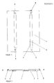
- Die Zeichnung zeigt in
- Fig. 1 eine Unteransicht einer Platte gemäß der Erfindung und in
- Fig. 2 einen Schnitt längs der Linie A-A der Fig.1.
- In Fig. 1 ist eine keramische Platte wiedergegeben, auf deren der Sichtseite abgewendeten Seite keramische versteifungsrippen 2 angeordnet sind. Außerdem greifen am Rand dieser keramischen Platte am Mauerwerk oder einer Unterkonstruktion befestigte Befestigungselemente 3 an. Die Versteifungsrippen 2 sind mit einer Glasur 4 auf der der Sichtseite abgewendeten Seite der Platte 1 befestigt, die schematisch angedeutet ist. Die Anordnung und Dimensionierung der Versteifungsrippen 2 erfolgt nach statischen Gesichtspunkten. Die Anordnung, wie sie sich aus der Zeichnung ergibt, muß nicht unbedingt zwingend sein. Das gleiche gilt für die Formgebung und Abmessungen der Versteifungsrippen 2.
Claims (4)
dadurch gekennzeichnet,
daß auf der der Sichtseite abgewendeten Seite der Platte (1) aus keramischem Material bestehende Versteifungsrippen (2) in nach statischen Gesichtspunkten gewählter Anordnung und/oder Dimensionierung dauerhaft befestigt sind.
dadurch gekennzeichnet,
das das keramische Material, aus dem die Versteifungsrippen (2) bestehen, den gleichen Wärmeausdehnungskoeffizienten aufweist, wie das Material der keramischen Platte (1).
dadurch gekennzeichnet,
daß bereits gebrannte Versteifungsrippen (2) auf einer bereits gebrannten Platte (1) mittels einer keramischen Glasur (4) dauerhaft befestigt sind, deren Schmelzpunkt unterhalb des Quarzumwandlungspunktes (573 C) liegt, wobei die mit den Versteifungsrippen (2) besetzte Platte (1) noch einmal auf eine Temperatur unterhalb des Quarzumwandlungspunktes erhitzt worden ist.
dadurch gekennzeichnet,
daß die zur dauerhaften Befestigung der Versteifungsrippen (2) auf der Platte (1) dienende keramische Glasur (4) den gleichen Wärmeausdehnungskoeffizienten wie die Platte (1) und/oder die Versteifungsrippen (2) aufweist.
Priority Applications (1)
| Application Number | Priority Date | Filing Date | Title |
|---|---|---|---|
| AT87100451T ATE48169T1 (de) | 1986-01-20 | 1987-01-15 | Grossformatige duennwandige keramische platte. |
Applications Claiming Priority (2)
| Application Number | Priority Date | Filing Date | Title |
|---|---|---|---|
| DE3601534 | 1986-01-20 | ||
| DE3601534 | 1986-01-20 |
Publications (3)
| Publication Number | Publication Date |
|---|---|
| EP0230271A2 true EP0230271A2 (de) | 1987-07-29 |
| EP0230271A3 EP0230271A3 (en) | 1988-05-04 |
| EP0230271B1 EP0230271B1 (de) | 1989-11-23 |
Family
ID=6292214
Family Applications (1)
| Application Number | Title | Priority Date | Filing Date |
|---|---|---|---|
| EP87100451A Expired EP0230271B1 (de) | 1986-01-20 | 1987-01-15 | Grossformatige dünnwandige keramische Platte |
Country Status (11)
| Country | Link |
|---|---|
| US (1) | US4815248A (de) |
| EP (1) | EP0230271B1 (de) |
| JP (1) | JPS62225642A (de) |
| AT (1) | ATE48169T1 (de) |
| DE (1) | DE3761026D1 (de) |
| DK (1) | DK164561C (de) |
| ES (1) | ES2011624B3 (de) |
| FI (1) | FI82516C (de) |
| NO (1) | NO870221L (de) |
| PT (1) | PT84150B (de) |
| ZA (1) | ZA87386B (de) |
Family Cites Families (14)
| Publication number | Priority date | Publication date | Assignee | Title |
|---|---|---|---|---|
| FR5544E (fr) * | 1903-02-26 | 1906-05-02 | Wenzel Ernst Miksch | Plaque de lambrissage |
| US2262973A (en) * | 1938-06-03 | 1941-11-18 | Sonnenschein Frank | Facing plate |
| FR1368121A (fr) * | 1963-01-25 | 1964-07-31 | Procédé de construction perfectionné | |
| US3826055A (en) * | 1970-10-26 | 1974-07-30 | Celotex Corp | Surface panel and mounting means therefor |
| FR2217502B3 (de) * | 1973-02-15 | 1976-02-13 | Barbier Jacques Fr | |
| NL181881C (nl) * | 1973-04-10 | 1987-11-16 | Eyk Johannes Felix Etienne Van | Veiligheidstegel. |
| US3868803A (en) * | 1973-06-04 | 1975-03-04 | Benson Mfg Corp | Plastic shutter and mounting clamp therefor |
| US3962504A (en) * | 1974-08-12 | 1976-06-08 | H & R Johnson-Richards Tiles Limited | Self-attaching tile of a fired ceramic tile body |
| JPS5430715U (de) * | 1977-08-03 | 1979-02-28 | ||
| FR2420622A1 (fr) * | 1978-03-24 | 1979-10-19 | Delattre Jean | Plancher demontable |
| JPS5738484U (de) * | 1980-08-12 | 1982-03-01 | ||
| US4468906A (en) * | 1981-09-17 | 1984-09-04 | Horst Miedaner | Blocks or bricks for the construction of a two-shell tile stove |
| US4433523A (en) * | 1981-09-17 | 1984-02-28 | Horst Miedaner | Block or brick for the construction of a two-shell tile stove |
| FR2559819A1 (fr) * | 1984-02-20 | 1985-08-23 | Boucourt Andre | Parement exterieur pour constructions |
-
1987
- 1987-01-15 ES ES87100451T patent/ES2011624B3/es not_active Expired - Lifetime
- 1987-01-15 EP EP87100451A patent/EP0230271B1/de not_active Expired
- 1987-01-15 DE DE8787100451T patent/DE3761026D1/de not_active Expired
- 1987-01-15 AT AT87100451T patent/ATE48169T1/de not_active IP Right Cessation
- 1987-01-19 NO NO870221A patent/NO870221L/no unknown
- 1987-01-20 DK DK030687A patent/DK164561C/da not_active IP Right Cessation
- 1987-01-20 JP JP62009170A patent/JPS62225642A/ja active Granted
- 1987-01-20 FI FI870224A patent/FI82516C/fi not_active IP Right Cessation
- 1987-01-20 PT PT84150A patent/PT84150B/pt not_active IP Right Cessation
- 1987-01-20 ZA ZA87386A patent/ZA87386B/xx unknown
- 1987-01-21 US US07/014,842 patent/US4815248A/en not_active Expired - Fee Related
Also Published As
| Publication number | Publication date |
|---|---|
| DK30687D0 (da) | 1987-01-20 |
| DK164561B (da) | 1992-07-13 |
| PT84150B (pt) | 1993-03-31 |
| EP0230271A3 (en) | 1988-05-04 |
| EP0230271B1 (de) | 1989-11-23 |
| ZA87386B (en) | 1987-10-28 |
| JPS62225642A (ja) | 1987-10-03 |
| FI82516C (fi) | 1991-03-11 |
| FI82516B (fi) | 1990-11-30 |
| NO870221L (no) | 1987-07-21 |
| JPH0511177B2 (de) | 1993-02-12 |
| US4815248A (en) | 1989-03-28 |
| FI870224A0 (fi) | 1987-01-20 |
| ATE48169T1 (de) | 1989-12-15 |
| NO870221D0 (no) | 1987-01-19 |
| DK30687A (da) | 1987-07-21 |
| DK164561C (da) | 1992-11-30 |
| FI870224L (fi) | 1987-07-21 |
| DE3761026D1 (en) | 1989-12-28 |
| PT84150A (de) | 1987-02-01 |
| ES2011624B3 (es) | 1990-02-01 |
Similar Documents
| Publication | Publication Date | Title |
|---|---|---|
| DE3021261C2 (de) | Feuerfeste Auskleidung eines Industrieofens zur Wärmebehandlung | |
| DE4004103A1 (de) | Wandelement fuer gebaeudeaussenwaende und verfahren zur herstellung eines wandelements | |
| EP0230271B1 (de) | Grossformatige dünnwandige keramische Platte | |
| EP0100431A1 (de) | Schall- und wärmedämmende Wandverkleidung | |
| DE4209834A1 (de) | Glasfassade an einer Tragstruktur | |
| DE1659558A1 (de) | Vorrichtung zur Befestigung von Verkleidungsplatten an Waenden u. dgl.,insbesondere fuer die Fassadenverkleidung an Bauwerken | |
| DE4026688A1 (de) | Fassadenverkleidung | |
| DE3406541C2 (de) | Vorrichtung zur Befestigung von Mehrscheiben-Isolierglas | |
| EP1160386B1 (de) | Hinterlüftete Fassade sowie Verfahren zur Herstellung einer hinterlüfteten Fassade | |
| DE7930208U1 (de) | Bauteilesatz zur herstellung und montage eines energiesammlers | |
| DE2611451C2 (de) | Dämmplatte zum Isolieren von Außen- und Innenflächen | |
| DE2904362A1 (de) | Lagergestell fuer kernreaktorbrennelemente | |
| EP0292847B1 (de) | Vorrichtung zum Errichten einer Wand, insbesondere aus Glasbausteinen | |
| DE10160462C2 (de) | Rahmenkonstruktion für einen Spiegel | |
| DE2516954A1 (de) | Vorrichtung zur befestigung von hinterluefteten fassaden-verkleidungsplatten | |
| DE3735786C2 (de) | ||
| DE9207858U1 (de) | Dachrinne | |
| DE202025104662U1 (de) | Justierbare Verankerungsvorrichtung für Fassadenelemente | |
| EP0302307A2 (de) | Paneel, insbesondere Fassadenplatte | |
| AT275823B (de) | Fliesenanordnung an einer Wand | |
| DE1609318C (de) | Großflächige Glaswand | |
| EP0183317A2 (de) | Doppelt verglastes, in einem Gewände und Masswerk angeordnetes Kirchenfenster | |
| DE2060296C3 (de) | Vorrichtung zur Halterung einer Fensterscheibe oder Platte in einem Rahmen oder einer Fensterlaibung | |
| DE1484025C (de) | Befestigung von Füllungen in einem Gerippefeld des Traggerippes einer Wand oder dergleichen | |
| AT220335B (de) | Wand- oder Dachverglasung |
Legal Events
| Date | Code | Title | Description |
|---|---|---|---|
| PUAI | Public reference made under article 153(3) epc to a published international application that has entered the european phase |
Free format text: ORIGINAL CODE: 0009012 |
|
| AK | Designated contracting states |
Kind code of ref document: A2 Designated state(s): AT BE CH DE ES FR GB IT LI LU NL SE |
|
| PUAL | Search report despatched |
Free format text: ORIGINAL CODE: 0009013 |
|
| AK | Designated contracting states |
Kind code of ref document: A3 Designated state(s): AT BE CH DE ES FR GB IT LI LU NL SE |
|
| 17P | Request for examination filed |
Effective date: 19880317 |
|
| 17Q | First examination report despatched |
Effective date: 19890201 |
|
| GRAA | (expected) grant |
Free format text: ORIGINAL CODE: 0009210 |
|
| AK | Designated contracting states |
Kind code of ref document: B1 Designated state(s): AT BE CH DE ES FR GB IT LI LU NL SE |
|
| REF | Corresponds to: |
Ref document number: 48169 Country of ref document: AT Date of ref document: 19891215 Kind code of ref document: T |
|
| ET | Fr: translation filed | ||
| REF | Corresponds to: |
Ref document number: 3761026 Country of ref document: DE Date of ref document: 19891228 |
|
| ITF | It: translation for a ep patent filed | ||
| GBT | Gb: translation of ep patent filed (gb section 77(6)(a)/1977) | ||
| PLBE | No opposition filed within time limit |
Free format text: ORIGINAL CODE: 0009261 |
|
| STAA | Information on the status of an ep patent application or granted ep patent |
Free format text: STATUS: NO OPPOSITION FILED WITHIN TIME LIMIT |
|
| 26N | No opposition filed | ||
| ITTA | It: last paid annual fee | ||
| PGFP | Annual fee paid to national office [announced via postgrant information from national office to epo] |
Ref country code: DE Payment date: 19920225 Year of fee payment: 6 |
|
| PGFP | Annual fee paid to national office [announced via postgrant information from national office to epo] |
Ref country code: GB Payment date: 19921216 Year of fee payment: 7 Ref country code: FR Payment date: 19921216 Year of fee payment: 7 |
|
| PGFP | Annual fee paid to national office [announced via postgrant information from national office to epo] |
Ref country code: SE Payment date: 19930122 Year of fee payment: 7 |
|
| PGFP | Annual fee paid to national office [announced via postgrant information from national office to epo] |
Ref country code: AT Payment date: 19930126 Year of fee payment: 7 |
|
| PGFP | Annual fee paid to national office [announced via postgrant information from national office to epo] |
Ref country code: LU Payment date: 19930127 Year of fee payment: 7 |
|
| PGFP | Annual fee paid to national office [announced via postgrant information from national office to epo] |
Ref country code: ES Payment date: 19930128 Year of fee payment: 7 |
|
| PGFP | Annual fee paid to national office [announced via postgrant information from national office to epo] |
Ref country code: NL Payment date: 19930131 Year of fee payment: 7 |
|
| PGFP | Annual fee paid to national office [announced via postgrant information from national office to epo] |
Ref country code: BE Payment date: 19930204 Year of fee payment: 7 |
|
| PGFP | Annual fee paid to national office [announced via postgrant information from national office to epo] |
Ref country code: CH Payment date: 19930217 Year of fee payment: 7 |
|
| EPTA | Lu: last paid annual fee | ||
| PG25 | Lapsed in a contracting state [announced via postgrant information from national office to epo] |
Ref country code: DE Effective date: 19931001 |
|
| PG25 | Lapsed in a contracting state [announced via postgrant information from national office to epo] |
Ref country code: LU Free format text: LAPSE BECAUSE OF NON-PAYMENT OF DUE FEES Effective date: 19940115 Ref country code: GB Effective date: 19940115 Ref country code: AT Effective date: 19940115 |
|
| PG25 | Lapsed in a contracting state [announced via postgrant information from national office to epo] |
Ref country code: SE Effective date: 19940116 |
|
| PG25 | Lapsed in a contracting state [announced via postgrant information from national office to epo] |
Ref country code: ES Free format text: LAPSE BECAUSE OF NON-PAYMENT OF DUE FEES Effective date: 19940117 |
|
| PG25 | Lapsed in a contracting state [announced via postgrant information from national office to epo] |
Ref country code: LI Effective date: 19940131 Ref country code: CH Effective date: 19940131 Ref country code: BE Effective date: 19940131 |
|
| BERE | Be: lapsed |
Owner name: BUCHTAL G.M.B.H. Effective date: 19940131 |
|
| PG25 | Lapsed in a contracting state [announced via postgrant information from national office to epo] |
Ref country code: NL Effective date: 19940801 |
|
| GBPC | Gb: european patent ceased through non-payment of renewal fee |
Effective date: 19940115 |
|
| NLV4 | Nl: lapsed or anulled due to non-payment of the annual fee | ||
| PG25 | Lapsed in a contracting state [announced via postgrant information from national office to epo] |
Ref country code: FR Effective date: 19940930 |
|
| REG | Reference to a national code |
Ref country code: CH Ref legal event code: PL |
|
| REG | Reference to a national code |
Ref country code: FR Ref legal event code: ST |
|
| EUG | Se: european patent has lapsed |
Ref document number: 87100451.1 Effective date: 19940810 |
|
| REG | Reference to a national code |
Ref country code: ES Ref legal event code: FD2A Effective date: 19990201 |
|
| PG25 | Lapsed in a contracting state [announced via postgrant information from national office to epo] |
Ref country code: IT Free format text: LAPSE BECAUSE OF NON-PAYMENT OF DUE FEES Effective date: 20050115 |