EP0228024B1 - Procédé pour intensifier les réactions entre le laitier et le bain et dispositif pour la mise en oeuvre de ce procédé - Google Patents
Procédé pour intensifier les réactions entre le laitier et le bain et dispositif pour la mise en oeuvre de ce procédé Download PDFInfo
- Publication number
- EP0228024B1 EP0228024B1 EP86117529A EP86117529A EP0228024B1 EP 0228024 B1 EP0228024 B1 EP 0228024B1 EP 86117529 A EP86117529 A EP 86117529A EP 86117529 A EP86117529 A EP 86117529A EP 0228024 B1 EP0228024 B1 EP 0228024B1
- Authority
- EP
- European Patent Office
- Prior art keywords
- melt
- stirring
- stirrer
- stirrers
- planes
- Prior art date
- Legal status (The legal status is an assumption and is not a legal conclusion. Google has not performed a legal analysis and makes no representation as to the accuracy of the status listed.)
- Expired
Links
- 238000000034 method Methods 0.000 title claims description 20
- 238000006243 chemical reaction Methods 0.000 title description 7
- 238000009877 rendering Methods 0.000 title 1
- 239000000155 melt Substances 0.000 claims description 40
- 238000003756 stirring Methods 0.000 claims description 24
- 239000002893 slag Substances 0.000 claims description 15
- 230000001939 inductive effect Effects 0.000 claims description 7
- 239000002184 metal Substances 0.000 claims description 6
- 230000001965 increasing effect Effects 0.000 claims description 3
- 239000011261 inert gas Substances 0.000 claims description 3
- NINIDFKCEFEMDL-UHFFFAOYSA-N Sulfur Chemical compound [S] NINIDFKCEFEMDL-UHFFFAOYSA-N 0.000 claims description 2
- 239000005864 Sulphur Substances 0.000 claims description 2
- 229910000831 Steel Inorganic materials 0.000 claims 1
- 239000010959 steel Substances 0.000 claims 1
- 230000033001 locomotion Effects 0.000 description 6
- 238000007654 immersion Methods 0.000 description 4
- 239000007789 gas Substances 0.000 description 3
- 238000007670 refining Methods 0.000 description 3
- 230000015572 biosynthetic process Effects 0.000 description 2
- 238000001816 cooling Methods 0.000 description 2
- 238000011161 development Methods 0.000 description 2
- 230000018109 developmental process Effects 0.000 description 2
- 238000010438 heat treatment Methods 0.000 description 2
- 238000009847 ladle furnace Methods 0.000 description 2
- 239000011819 refractory material Substances 0.000 description 2
- 206010013710 Drug interaction Diseases 0.000 description 1
- 230000005587 bubbling Effects 0.000 description 1
- 238000010891 electric arc Methods 0.000 description 1
- 239000012530 fluid Substances 0.000 description 1
- 230000003993 interaction Effects 0.000 description 1
- 239000002245 particle Substances 0.000 description 1
- 230000035515 penetration Effects 0.000 description 1
- 230000002093 peripheral effect Effects 0.000 description 1
- XLYOFNOQVPJJNP-UHFFFAOYSA-N water Substances O XLYOFNOQVPJJNP-UHFFFAOYSA-N 0.000 description 1
Images
Classifications
-
- F—MECHANICAL ENGINEERING; LIGHTING; HEATING; WEAPONS; BLASTING
- F27—FURNACES; KILNS; OVENS; RETORTS
- F27D—DETAILS OR ACCESSORIES OF FURNACES, KILNS, OVENS OR RETORTS, IN SO FAR AS THEY ARE OF KINDS OCCURRING IN MORE THAN ONE KIND OF FURNACE
- F27D27/00—Stirring devices for molten material
-
- B—PERFORMING OPERATIONS; TRANSPORTING
- B01—PHYSICAL OR CHEMICAL PROCESSES OR APPARATUS IN GENERAL
- B01F—MIXING, e.g. DISSOLVING, EMULSIFYING OR DISPERSING
- B01F33/00—Other mixers; Mixing plants; Combinations of mixers
- B01F33/45—Magnetic mixers; Mixers with magnetically driven stirrers
- B01F33/451—Magnetic mixers; Mixers with magnetically driven stirrers wherein the mixture is directly exposed to an electromagnetic field without use of a stirrer, e.g. for material comprising ferromagnetic particles or for molten metal
-
- C—CHEMISTRY; METALLURGY
- C21—METALLURGY OF IRON
- C21C—PROCESSING OF PIG-IRON, e.g. REFINING, MANUFACTURE OF WROUGHT-IRON OR STEEL; TREATMENT IN MOLTEN STATE OF FERROUS ALLOYS
- C21C7/00—Treating molten ferrous alloys, e.g. steel, not covered by groups C21C1/00 - C21C5/00
- C21C7/0075—Treating in a ladle furnace, e.g. up-/reheating of molten steel within the ladle
-
- B—PERFORMING OPERATIONS; TRANSPORTING
- B01—PHYSICAL OR CHEMICAL PROCESSES OR APPARATUS IN GENERAL
- B01F—MIXING, e.g. DISSOLVING, EMULSIFYING OR DISPERSING
- B01F2101/00—Mixing characterised by the nature of the mixed materials or by the application field
- B01F2101/45—Mixing in metallurgical processes of ferrous or non-ferrous materials
-
- F—MECHANICAL ENGINEERING; LIGHTING; HEATING; WEAPONS; BLASTING
- F27—FURNACES; KILNS; OVENS; RETORTS
- F27B—FURNACES, KILNS, OVENS OR RETORTS IN GENERAL; OPEN SINTERING OR LIKE APPARATUS
- F27B3/00—Hearth-type furnaces, e.g. of reverberatory type; Electric arc furnaces ; Tank furnaces
- F27B3/08—Hearth-type furnaces, e.g. of reverberatory type; Electric arc furnaces ; Tank furnaces heated electrically, with or without any other source of heat
- F27B3/085—Arc furnaces
-
- F—MECHANICAL ENGINEERING; LIGHTING; HEATING; WEAPONS; BLASTING
- F27—FURNACES; KILNS; OVENS; RETORTS
- F27D—DETAILS OR ACCESSORIES OF FURNACES, KILNS, OVENS OR RETORTS, IN SO FAR AS THEY ARE OF KINDS OCCURRING IN MORE THAN ONE KIND OF FURNACE
- F27D3/00—Charging; Discharging; Manipulation of charge
- F27D2003/0034—Means for moving, conveying, transporting the charge in the furnace or in the charging facilities
- F27D2003/0039—Means for moving, conveying, transporting the charge in the furnace or in the charging facilities comprising magnetic means
-
- F—MECHANICAL ENGINEERING; LIGHTING; HEATING; WEAPONS; BLASTING
- F27—FURNACES; KILNS; OVENS; RETORTS
- F27D—DETAILS OR ACCESSORIES OF FURNACES, KILNS, OVENS OR RETORTS, IN SO FAR AS THEY ARE OF KINDS OCCURRING IN MORE THAN ONE KIND OF FURNACE
- F27D3/00—Charging; Discharging; Manipulation of charge
- F27D3/16—Introducing a fluid jet or current into the charge
- F27D2003/167—Introducing a fluid jet or current into the charge the fluid being a neutral gas
Definitions
- the invention relates to a method for mixing slag-metal baths and an arrangement for carrying out the method according to the precharacterising part of claim 1. Such a method is describes in the DE-A-1 903 212.
- the DE-A-1 903 212 describes means for stirring metal melt which means comprises two stirrers arranged on opposite sides of a ladle filled with melt. While the upper portions of the stirrers are arranged vertically, the lower portions are arranged in an inclined position. This arrangement is selected so that the direction of the moving field generated by the stirrers and the direction of the force exerted on the melt by these fields are positioned in vertical planes. Forces imparted on the melt and acting in horizontal planes are not generated by this known stirring device.
- the EP-A-0 103 534 describes means for imparting motion on a melt in ladle.
- the melt is heated by a centrally arranged arc electrode and a marginally arranged bottom contact electrode.
- the heating current that spreads from the central point of the electric arc to the periphery at the bottom of the ladle causes a predominantly vertical movement of the melt that is directed downwards in the vicinity of the vertical centre line of the ladle and vertically upwards in the peripheral parts of the ladle.
- the ladle is surrounded by a circular coil which is supplied with direct current. By inter-action of the stationary continuous magnetic field generated by this coil and the current flowing through the melt an additional rotational movement about a vertical axis is generated.
- the invention aims at a method of the above-mentioned kind which brings about a very efficient slag-bath reaction and thus allows to shorten the time of treatment. It is a further object of the invention to develop an arrangement for carrying out the method.
- An arrangement for carrying out the method is characterized by the features of claim 7.
- the method according to the invention provides rotary as well as vertical stirring of the melt.
- the slag stirring is improved and in this way the transport of "new" slag to the reaction zone is accelerated.
- the invention includes one embodiment with at least two different stirrers.
- One of the stirrers develops forces acting in vertical planes on the melt while the other stirrer develops forces acting in horizontal planes on the melt. Both forces are able to create rotational movements of the melts in their respective planes.
- Another embodiment of the invention which is able to generate a similar pattern of stirring, comprises at least one stirrer that is arranged obliquely in such a way as to create both, force components on the melt acting in vertical planes and force components on the melt acting in horizontal planes.
- a lance is immersed into the melt to a depth of 0 - 1000 mm below the slag, inert gas being blown through the lance in the course of the stirring.
- This increases the rate of mixing between slag and melt.
- the cost of the lance can be kept low. This is also made possible by water-cooling that part of the lance which is located above the slag surface and by making the lower part of the lance replaceable and of a refractory material.
- stirrers located adjacent each other or at peripherally separated portions of the furnace or ladle, the stirrers being controlled individually as regards the amplitude, direction and frequency of the current for achieving different stirring forces.
- This arrangement increases the turbulence, which is advantageous for refining reactions.
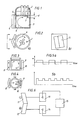
- Figures 1 and 2 show a ladle furnace or other furnace with arcing electrodes, for example in a three-phase arrangement.
- An immersion lance 2 is immersed 0-1000 mm (see measure d in Figure 1) below the surface of the slag 4 of the melt 3.
- An inductive, multiphase stirrer 5 is mounted at the side of the furnace and has an upward stirring direction (see arrow 6 in Figure 1). This stirring direction can be varied.
- the method comprises intensifying the mixing rate between slag 4 and melt 3 by means of gas bubbling in combination with inductive stirring of the metal melt by means of the stirrer 5 (see arrow 6).
- the gas supplied through the lance 2 exits into the melt 3 at the distance d (see Figure 1) below the slag surface 4.
- the gas which is suitably and inert gas, is supplied below the surface of the melt 3. That part of the lance 2 which is located above the slag surface is suitably provided with means for water cooling and the lower, replaceable part 7 is made of a refractory material.
- the inductive stirring is arranged such that a rotary movement is imparted to the slag 4 and the melt 3 while at the same time a vertical bulk stirring is obtained in the melt 3, for example by placing the stirrer 5 in an inclined position as shown in Figure 2b or by adjusting it in some other way (described below).
- the travelling field develops one component in the horizontal direction and one in the vertical direction, the horizontal component producing a rotary movement indicated by the arrow 6 in Figure 2a.
- the slag 4 rotates, the slag is continuously renewed in the reaction zone. Because of the limited depth of immersion of the lance 2 and of the water-cooled upper part of the lance 2, the cost of the lance 2 can be kept low.
- the method can be carried out during simultaneous heating of the melt 3 by means of the electrodes 1.
- a pole (not shown, e. g. a refractory pole) can be immersed into the melt 3 for disturbing the fluid flow pattern, which increases the turbulence as well as the mass transfer between slag and melt.
- FIGs 3 and 4 show an arrangement with two stirrers, namely, one vertical stirrer 8 and one horizontal stirrer 9, which are located on opposite sides of the ladle or furnace 10.
- the vertical and the horizontal component for the travelling field are each obtained in this case by a different stirrer.
- the arrangement can be employed, for example, as follows:
- the melt is stirred by the combination of the two inductive stirrers 8, 9, one stirrer 8 moving the melt substantially in a vertical direction as indicated by the arrows in Figure 3 and the other stirrer 9 moving the melt in a horizontal (tangential) direction as indicated by arrows in Figure 4.
- the stirring direction can be changed intermittently (see Figures 5a and 5b), which results in the formation of eddies.
- the eddy formation causes the slag particles to be drawn down into the melt.
- the change of direction may take place at a frequency of about 0,5 - 0,05 times per second.
- the frequency can also be varied temporarily for the tangential stirrer 9 in order to change the depth of penetration and hence the distribution of power.
- the change of direction can also take place with the vertical stirrer 8.
- the aim of the arrangement according to Figures 3 - 5 is also to improve the slag-bath mass transfer, thus achieving improved refining.
- the x-axis shows the time and the y-axis the direction of the stirring of the horizontal stirrer 9.
- Figure 5b shows a change of the frequency f (ordinate) of the same stirrer using another variant of stirring.
- Figure 6 shows a device in which the stirrer is divided into two parts, for example two halves, 11, 12, each being fed separately from an individual thyristor unit 13, 14. This provides a possibility of controlling the two parts individually by means of a control device 15 with respect to current amplitude, direction and frequency. Program control is also possible.
Landscapes
- Chemical & Material Sciences (AREA)
- Engineering & Computer Science (AREA)
- Chemical Kinetics & Catalysis (AREA)
- Materials Engineering (AREA)
- Metallurgy (AREA)
- Organic Chemistry (AREA)
- Mechanical Engineering (AREA)
- General Engineering & Computer Science (AREA)
- Treatment Of Steel In Its Molten State (AREA)
- Furnace Details (AREA)
- Manufacture And Refinement Of Metals (AREA)
- Waste-Gas Treatment And Other Accessory Devices For Furnaces (AREA)
Claims (8)
- Procédé pour le mélange de laitiers et de bains de métal en fusion, par exemple en relation avec l'extraction du soufre présent dans l'acier, par l'agitation du bain en fusion au moyen d'au moins un agitateur inductif dont le champ mobile génère dans le bain en fusion une force qui agit dans des plans verticaux et est capable de faire tourner le bain en fusion dans ces plans verticaux, caractérisé en ce que le champ mobile agissant sur le bain en fusion génère également une composante de force qui agit sur le bain en fusion dans des plans horizontaux et qui est capable de faire tourner le bain en fusion dans ces plans horizontaux, et en ce que l'agitation est effectuée soit au moyen d'au moins deux agitateurs, l'un d'eux générant une force d'agitation dans chacun des plans précités, les agitateurs étant de préférence placés sur des côtés opposés d'un four ou d'une poche de coulée contenant le bain en fusion, soit au moyen d'au moins un agitateur qui est positionné de façon oblique par rapport au four ou à la poche de coulée contenant le bain en fusion.
- Procédé selon la revendication 1, caractérisé en ce qu'on change de façon répétée la direction des forces d'agitation dans les plans verticaux et/ou horizontaux.
- Procédé selon la revendication 1 ou 2, caractérisé en ce qu'une lance est immergée dans le bain en fusion à une profondeur de 0-100 mm au-dessous de la surface du laitier, et un gaz de préférence inerte est soufflé à travers la lance au cours de l'agitation.
- Procédé selon l'une quelconque des revendications précédentes, caractérisé en ce qu'une perche ou un dispositif semblable est immergé dans le bain en fusion de façon à perturber le processus d'agitation et à provoquer ainsi une turbulence accrue.
- Procédé selon la revendication 1 ou 4, caractérisé en ce qu'on réalise l'agitation au moyen de deux agitateurs juxtaposés, qui sont commandés individuellement de façon à fonctionner avec une amplitude, une direction et une fréquence de courant différentes.
- Procédé selon la revendication 1, 4 ou 5, caractérisé en ce qu'on réalise l'agitation au moyen de deux agitateurs séparés disposés dans des positions périphériques.
- Dispositif pour mettre en oeuvre le procédé selon l'une quelconque des revendications précédentes, comprenant au moins un agitateur inductif (5, 8), qui est conçu de façon à générer un champ magnétique mobile et qui est disposé près de la paroi du four ou de la poche de coulée contenant le bain en fusion, avec une orientation telle que la force que génère le champ mobile agisse sur le bain en fusion dans des plans verticaux, caractérisé en ce qu'au moins un second agitateur (8) est disposé près de la paroi du four ou de la poche de coulée contenant le bain en fusion, avec une orientation telle que la force qui est générée par son champ mobile agisse sur le bain en fusion dans des plans horizontaux, ou bien l'agitateur inductif mentionné en premier (5) est orienté de façon oblique, de manière que la force qui est générée par son champ mobile produise une composante qui agit sur le bain en fusion dans des plans verticaux, ainsi qu'une composante qui agit sur le bain en fusion dans des plans horizontaux.
- Dispositif selon la revendication 7, caractérisé en ce qu'il comprend au moins deux agitateurs juxtaposés ou séparés dans des positions périphériques.
Applications Claiming Priority (2)
| Application Number | Priority Date | Filing Date | Title |
|---|---|---|---|
| SE8506060 | 1985-12-20 | ||
| SE8506060A SE452991B (sv) | 1985-12-20 | 1985-12-20 | Sett och anordning for att effektivisera slagg-/badreaktioner medelst induktiv omroring |
Publications (3)
| Publication Number | Publication Date |
|---|---|
| EP0228024A2 EP0228024A2 (fr) | 1987-07-08 |
| EP0228024A3 EP0228024A3 (en) | 1988-03-30 |
| EP0228024B1 true EP0228024B1 (fr) | 1992-09-02 |
Family
ID=20362551
Family Applications (1)
| Application Number | Title | Priority Date | Filing Date |
|---|---|---|---|
| EP86117529A Expired EP0228024B1 (fr) | 1985-12-20 | 1986-12-17 | Procédé pour intensifier les réactions entre le laitier et le bain et dispositif pour la mise en oeuvre de ce procédé |
Country Status (5)
| Country | Link |
|---|---|
| US (1) | US4778518A (fr) |
| EP (1) | EP0228024B1 (fr) |
| JP (1) | JPS62156220A (fr) |
| DE (1) | DE3686641T2 (fr) |
| SE (1) | SE452991B (fr) |
Families Citing this family (10)
| Publication number | Priority date | Publication date | Assignee | Title |
|---|---|---|---|---|
| SE460621B (sv) * | 1987-04-13 | 1989-10-30 | Asea Ab | Saett att minska foderslitage vid ljusbaagsvaermning av staalsmaeltor i skaenk |
| SE464263B (sv) * | 1988-09-21 | 1991-03-25 | Asea Brown Boveri | Metod och anordning foer omroerning av en metallsmaelta |
| WO1991019013A1 (fr) * | 1990-05-31 | 1991-12-12 | Nippon Steel Corporation | Procede de raffinage pour metaux ou alliages en fusion |
| SE504400C2 (sv) * | 1995-04-25 | 1997-02-03 | Asea Brown Boveri | Ugnsanläggning för smältning av metall och/eller varmhållning av smält metall |
| FR2840821B1 (fr) * | 2002-06-13 | 2005-03-04 | Commissariat Energie Atomique | Dispositif electromagnetique de fusion et d'agitation interfaciale de systemes diphasiques, notamment pour l'acceleration de processus metallurgiques ou pyrochimiques |
| WO2003106908A1 (fr) * | 2002-06-15 | 2003-12-24 | Solios Thermal Limited | Dispositif a induction electromagnetique et procede pour traiter des materiaux en fusion |
| US7651656B2 (en) * | 2006-07-20 | 2010-01-26 | Kenzo Takahashi | Melting furnace with agitator and agitator for melting furnace |
| ES2606237T3 (es) | 2011-07-18 | 2017-03-23 | Abb Research Ltd. | Procedimiento y sistema de control para controlar un proceso de fusión |
| BR112019014882B1 (pt) | 2017-02-10 | 2022-03-03 | Abb Schweiz Ag | Montagem de forno para um processo de produção de metal |
| CN110055369B (zh) * | 2019-05-21 | 2020-11-20 | 武汉钢铁有限公司 | 铁水kr脱硫搅拌器粘渣快速清理方法 |
Family Cites Families (6)
| Publication number | Priority date | Publication date | Assignee | Title |
|---|---|---|---|---|
| GB523605A (en) * | 1938-01-24 | 1940-07-18 | Kjell Magnus Tigerschiold | Improvements relating to the desulphurization of pig iron |
| SE329410B (fr) * | 1968-01-31 | 1970-10-12 | Asea Ab | |
| SU435286A1 (ru) * | 1970-10-21 | 1974-07-05 | Л. П. Пужайло, В. П. Полищук , В. К. Погорский Институт проблем лить | Индукционная канальная печь |
| US3704476A (en) * | 1971-11-26 | 1972-12-05 | Daniel C Hanna | Wraparound brushing devices |
| SE447846B (sv) * | 1982-09-09 | 1986-12-15 | Asea Ab | Skenkugn med likstromsvermning |
| JPS59150009A (ja) * | 1983-02-12 | 1984-08-28 | Daido Steel Co Ltd | 鋼の精錬方法 |
-
1985
- 1985-12-20 SE SE8506060A patent/SE452991B/sv not_active IP Right Cessation
-
1986
- 1986-12-17 EP EP86117529A patent/EP0228024B1/fr not_active Expired
- 1986-12-17 DE DE8686117529T patent/DE3686641T2/de not_active Expired - Fee Related
- 1986-12-18 JP JP61302731A patent/JPS62156220A/ja active Pending
- 1986-12-18 US US06/943,929 patent/US4778518A/en not_active Expired - Fee Related
Also Published As
| Publication number | Publication date |
|---|---|
| EP0228024A3 (en) | 1988-03-30 |
| JPS62156220A (ja) | 1987-07-11 |
| SE8506060L (sv) | 1987-06-21 |
| EP0228024A2 (fr) | 1987-07-08 |
| SE452991B (sv) | 1988-01-04 |
| US4778518A (en) | 1988-10-18 |
| DE3686641T2 (de) | 1993-04-08 |
| DE3686641D1 (de) | 1992-10-08 |
| SE8506060D0 (sv) | 1985-12-20 |
Similar Documents
| Publication | Publication Date | Title |
|---|---|---|
| EP0228024B1 (fr) | Procédé pour intensifier les réactions entre le laitier et le bain et dispositif pour la mise en oeuvre de ce procédé | |
| RU2266798C2 (ru) | Способ и устройство для непрерывной разливки металлов в кристаллизатор | |
| US7449143B2 (en) | Systems and methods of electromagnetic influence on electroconducting continuum | |
| EP4192638B1 (fr) | Dispositif d'agitation et procédé pour four de fusion et four de fusion | |
| US3918692A (en) | Apparatus for refining molten metals and molten metal refining process | |
| Garnier | Electromagnetic processing of liquid materials in Europe | |
| US5058127A (en) | Bottom discharge cold crucible | |
| US3820767A (en) | Apparatus for the treatment of molten metal | |
| JPS6227139B2 (fr) | ||
| US4169962A (en) | Heat treating apparatus | |
| KR100556715B1 (ko) | 미세 금속 입자 및/또는 금속 함유 입자를 용융시키기위한 방법 및 유도 전기로 | |
| JPS6213410B2 (fr) | ||
| JP7026693B2 (ja) | 金属製造プロセスのための炉アセンブリ | |
| EP0286934B1 (fr) | Procédé pour réduire l'usure des revêtements d'une poche contenant des matériaux fondus | |
| US3621103A (en) | Methods of and apparatus for stirring immiscible conductive fluids | |
| CA2218016A1 (fr) | Methode de brassage electromagnetique du metal liquide dans les fours electriques a arc et dispositif connexe | |
| US5738823A (en) | Meltdown apparatus | |
| US3653879A (en) | Rotary reactor and method for treating melts | |
| JPH11124619A (ja) | 取鍋内溶鋼電磁攪拌装置 | |
| RU2104607C1 (ru) | Способ электромагнитного управления вращательным движением электропроводного тела | |
| US4279642A (en) | Method for electroslag remelting of metals | |
| WO1987006332A1 (fr) | Dispositif pour la fabrication d'acier, avec agitation inductive | |
| WO1990003544A1 (fr) | Procede d'agitation asymetrique d'un metal en fusion et dipositif de realisation dudit procede | |
| CA1149177A (fr) | Methode de refonte des metaux au four a arc | |
| JPH0361318B2 (fr) |
Legal Events
| Date | Code | Title | Description |
|---|---|---|---|
| PUAI | Public reference made under article 153(3) epc to a published international application that has entered the european phase |
Free format text: ORIGINAL CODE: 0009012 |
|
| AK | Designated contracting states |
Kind code of ref document: A2 Designated state(s): DE FR GB IT |
|
| PUAL | Search report despatched |
Free format text: ORIGINAL CODE: 0009013 |
|
| AK | Designated contracting states |
Kind code of ref document: A3 Designated state(s): DE FR GB IT |
|
| 17P | Request for examination filed |
Effective date: 19880927 |
|
| 17Q | First examination report despatched |
Effective date: 19900514 |
|
| GRAA | (expected) grant |
Free format text: ORIGINAL CODE: 0009210 |
|
| AK | Designated contracting states |
Kind code of ref document: B1 Designated state(s): DE FR GB IT |
|
| REF | Corresponds to: |
Ref document number: 3686641 Country of ref document: DE Date of ref document: 19921008 |
|
| ET | Fr: translation filed | ||
| ITF | It: translation for a ep patent filed | ||
| PLBE | No opposition filed within time limit |
Free format text: ORIGINAL CODE: 0009261 |
|
| STAA | Information on the status of an ep patent application or granted ep patent |
Free format text: STATUS: NO OPPOSITION FILED WITHIN TIME LIMIT |
|
| 26N | No opposition filed | ||
| PGFP | Annual fee paid to national office [announced via postgrant information from national office to epo] |
Ref country code: FR Payment date: 19981209 Year of fee payment: 13 |
|
| PGFP | Annual fee paid to national office [announced via postgrant information from national office to epo] |
Ref country code: GB Payment date: 19981218 Year of fee payment: 13 |
|
| PGFP | Annual fee paid to national office [announced via postgrant information from national office to epo] |
Ref country code: DE Payment date: 19981229 Year of fee payment: 13 |
|
| PG25 | Lapsed in a contracting state [announced via postgrant information from national office to epo] |
Ref country code: GB Free format text: LAPSE BECAUSE OF NON-PAYMENT OF DUE FEES Effective date: 19991217 |
|
| GBPC | Gb: european patent ceased through non-payment of renewal fee |
Effective date: 19991217 |
|
| PG25 | Lapsed in a contracting state [announced via postgrant information from national office to epo] |
Ref country code: FR Free format text: LAPSE BECAUSE OF NON-PAYMENT OF DUE FEES Effective date: 20000831 |
|
| PG25 | Lapsed in a contracting state [announced via postgrant information from national office to epo] |
Ref country code: DE Free format text: LAPSE BECAUSE OF NON-PAYMENT OF DUE FEES Effective date: 20001003 |
|
| REG | Reference to a national code |
Ref country code: FR Ref legal event code: ST |
|
| PG25 | Lapsed in a contracting state [announced via postgrant information from national office to epo] |
Ref country code: IT Free format text: LAPSE BECAUSE OF NON-PAYMENT OF DUE FEES;WARNING: LAPSES OF ITALIAN PATENTS WITH EFFECTIVE DATE BEFORE 2007 MAY HAVE OCCURRED AT ANY TIME BEFORE 2007. THE CORRECT EFFECTIVE DATE MAY BE DIFFERENT FROM THE ONE RECORDED. Effective date: 20051217 |