EP0226783A2 - Safety closure - Google Patents
Safety closure Download PDFInfo
- Publication number
- EP0226783A2 EP0226783A2 EP86115494A EP86115494A EP0226783A2 EP 0226783 A2 EP0226783 A2 EP 0226783A2 EP 86115494 A EP86115494 A EP 86115494A EP 86115494 A EP86115494 A EP 86115494A EP 0226783 A2 EP0226783 A2 EP 0226783A2
- Authority
- EP
- European Patent Office
- Prior art keywords
- closure
- ring
- container
- flange
- tabs
- Prior art date
- Legal status (The legal status is an assumption and is not a legal conclusion. Google has not performed a legal analysis and makes no representation as to the accuracy of the status listed.)
- Withdrawn
Links
Images

Classifications
-
- B—PERFORMING OPERATIONS; TRANSPORTING
- B65—CONVEYING; PACKING; STORING; HANDLING THIN OR FILAMENTARY MATERIAL
- B65D—CONTAINERS FOR STORAGE OR TRANSPORT OF ARTICLES OR MATERIALS, e.g. BAGS, BARRELS, BOTTLES, BOXES, CANS, CARTONS, CRATES, DRUMS, JARS, TANKS, HOPPERS, FORWARDING CONTAINERS; ACCESSORIES, CLOSURES, OR FITTINGS THEREFOR; PACKAGING ELEMENTS; PACKAGES
- B65D47/00—Closures with filling and discharging, or with discharging, devices
- B65D47/04—Closures with discharging devices other than pumps
- B65D47/06—Closures with discharging devices other than pumps with pouring spouts or tubes; with discharge nozzles or passages
- B65D47/061—Closures with discharging devices other than pumps with pouring spouts or tubes; with discharge nozzles or passages with telescopic, retractable or reversible spouts, tubes or nozzles
- B65D47/063—Closures with discharging devices other than pumps with pouring spouts or tubes; with discharge nozzles or passages with telescopic, retractable or reversible spouts, tubes or nozzles with flexible parts
-
- B—PERFORMING OPERATIONS; TRANSPORTING
- B65—CONVEYING; PACKING; STORING; HANDLING THIN OR FILAMENTARY MATERIAL
- B65D—CONTAINERS FOR STORAGE OR TRANSPORT OF ARTICLES OR MATERIALS, e.g. BAGS, BARRELS, BOTTLES, BOXES, CANS, CARTONS, CRATES, DRUMS, JARS, TANKS, HOPPERS, FORWARDING CONTAINERS; ACCESSORIES, CLOSURES, OR FITTINGS THEREFOR; PACKAGING ELEMENTS; PACKAGES
- B65D47/00—Closures with filling and discharging, or with discharging, devices
- B65D47/04—Closures with discharging devices other than pumps
- B65D47/06—Closures with discharging devices other than pumps with pouring spouts or tubes; with discharge nozzles or passages
- B65D47/12—Closures with discharging devices other than pumps with pouring spouts or tubes; with discharge nozzles or passages having removable closures
- B65D47/122—Threaded caps
Definitions
- the invention relates to a guarantee closure for liquid containers with an insert ring with flange to be inserted into a generally circular opening of the container, a pouring spout, a closure lid closing the pouring spout, a bellows connecting the insert ring and the pouring spout and a hinged ring bracket attached to the closure lid in at least one point .
- Such closures have long been known both for metal and for plastic or cardboard containers.
- the insert ring of the closure serves to fix the closure in the container opening in a liquid-tight manner.
- Etalldeckeln in closures for metal containers and for containers with M includes this insert ring has a circumferential annular groove, into which the flanged edge of the container mounted in the cover and engages a generally circular opening.
- This groove is formed by an annular bead-like projection, which is formed below the groove on the outside of the insert ring, and by a flange, which generally forms the upper edge of the insert ring and which rests on the surface of the container lid immediately surrounding the opening.
- the insert ring is made of a relatively soft plastic (e.g. high-pressure polyethylene), it is possible to insert it into the container opening with a certain amount of force, whereby the annular bead-like projection, which has a larger outer diameter than the container opening, is briefly compressed and collapses then expands back to its previous extent.
- a relatively soft plastic e.g. high-pressure polyethylene
- the diameter of the ring groove, the projection, the container opening and the flange are chosen so that the inserted plastic ring rests liquid-tight on the edge of the container opening, the flange preventing the closure from being pressed fully into the interior of the container, while the projection pulls out the entire closure prevent container opening.
- the insert ring is generally connected via a bellows to a pouring spout, which in turn is closed by a cover.
- the bellows can be turned in and out, and the pouring spout and bellows are dimensioned such that the closure lid sitting on the pouring spout is essentially flush with the surface of the container or protrudes only slightly over the surface of the container, while the pouring spout is in the turned-out state is located at a clear distance above the container surface, which makes it easier to pour out the liquid in the container.
- one R is attached to the closure cap, which is screwed, in general, with the pouring spout attached ingbügel so that is pulled out in a strong train on the ring-pull of the cap with the spout by the eversion of the bellows out of the insert ring.
- the projection of the insert ring must absorb the forces that occur without sliding through the container opening.
- the invention is therefore based on the object of providing a closure for liquid containers with the features mentioned at the outset, which can practically not be removed from the container opening without externally clearly visible changes.
- covers at unopened closure of the annular strap, together with the closure lid flange broadly and encompasses that the R closely abuts the opening surrounding container surface ingbügel that by manually tearable tabs he at least in its flip-up region with the Closure cover is connected and / or that the closure cover and / or the ring bracket by appropriate tabs with the insert ring or Container surface are connected.
- the insert ring must be ovalized and pried out or pulled out of the opening in order to remove the closure from the container.
- the insert ring cannot be reached without first lifting the ring bracket and / or the closure cover and thus at least partially bulging out the bellows.
- this provides a noticeable resistance to the lifting of the cover, whereby the tabs, which connect either the ring bracket and the cover ring or the ring bracket and the insert ring or the closure cover and the insert ring, tear and so make any attempt at manipulation obvious.
- connection options of the tabs are not mutually exclusive and can be present at the same closure at the same time. In general, however, one type of connection is sufficient to ensure the purpose of the invention.
- the tabs have predetermined breaking points.
- Such predetermined breaking points can be arranged so that the torn tabs are clearly visible from the outside.
- the tabs are under a pretension, by means of which, after they have been torn off, their free end visibly protrudes from their previous attachment point.
- Such a design of the tabs facilitates the detection of tampering with the container closure.
- Ringbü g el and / or the closure cover with tabs diametrically opposite welding strips are connected, which in turn have a large-area welded connection to the flange of the insert ring.
- the ring bracket covers a bead concentrically surrounding the container opening and the flange of the insert ring in the container surface.
- closure cap is a screw having a toothing in the outer region of its underside which engages with un g eworkem closure in a counter toothing which is mounted on the surface of the flange, in the form of an anti-rotation .
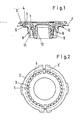
- the closure shown in FIGS. 1 and 2 has practically along the entire circumference of the closure cover 1 tabs 3 which are connected to the ring bracket 2 at predetermined breaking points 4.
- the R ingbügel 2 encloses both the cap 1 and the flange 5 of the insert ring 6.
- closure cap 1 and ring bracket 2 together cover the flange 5 of the insert ring 6 completely.
- the container surface 7 also has a step-shaped shoulder 8 which surrounds the container opening in a ring, so that the flange 5 lies in a corresponding recess.
- the ring bracket 2 lies outside the shoulder 8 on the container surface 7.
- the insert ring 6 by gripping under the flange 5 to be levered out of the container opening, the ingbügel R 2 must be raised a considerable piece for this purpose necessarily.
- the tabs 3 tear off at the predetermined breaking points 4 from the ring bracket 2 and thus make the attempt at manipulation obvious.
- the closure cap 1 as in all the other embodiments shown here, is designed as a screw cap, which is screwed onto the pouring spout 10 firmly and in a liquid-tight manner via the thread 9.
- the pouring spout 10 is connected to the insert ring 6 via the bellows 11.
- Fig. 2 also tabs 3 'can be seen, which have no predetermined breaking points 4 and thus produce a flexible, but nevertheless firm connection between the semicircular parts of the ring bracket 2 and the closure cover 1.
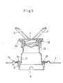
- FIGS. 3 to 5 differs from the aforementioned embodiment in several respects.
- the surface of the container has an annular bead 14 running around the container opening.
- this ring bead 14 is completely covered by the ring bracket 2.
- the flange 5 cannot be levered up by tools or the like without the ring bracket 2 being raised and the tabs 3 thus being torn off.
- 3 to 5 are additional to the tabs 3 and 3 'to recognize further tabs 3a, which establish a connection between the closure cover 1 and the flange 5 of the insert ring 6.
- the embodiment shown here also has an inner membrane seal 12 which closes the pouring spout 10 in its interior and can be pulled out by a ring 13. Furthermore, the already mentioned toothing 15, which acts as an anti-rotation device, is indicated in FIG. 4 by dashed lines.
- Fig. 5 shows the closure just described in everted condition, whereby the individual parts, in particular the closure cap 1, the R ingbügel 2 and the torn off flap 3a can be seen very clearly.
- the fastening g ung the tab 3a on the flange 5 is effected by ultrasonic welding.
- the insert ring 6 shown in FIG. 5 has a notch or a groove 16 in its lower region, through which the residual emptying of the container is improved.
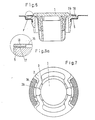
- FIGs. 6, 6a and 7 another embodiment is shown, in which the R 2 ingbügel- 3b via tabs welding strips 18 attached, which are joined by ultrasonic welding firmly to the flange 5 of the insert ring 6.
- This ensures that the ring bracket 2 and / or the closure cover 1 can only be lifted off the flange 5 by tearing the tabs 3b, so that any manipulation of the Contents of the container, which would be accomplished by prying out or pulling the entire closure out of the container opening, are immediately visible.
- Strength in F. 6a is a detail from FIG. 6, but is shown before the welded connection is made. In this ar- D position to recognize the energy directors 17, which can be seen as a wedge-shaped elevation of the flange. 5 Such e nergieggisgeber is very convenient for the placement of the ultrasonic energy in the desired range.
- FIGS. 1 to 5 have locking cams 19 on the outer edge of the closure cover 1, which is designed as a screw cap in all other embodiments, which can be locked into locking grooves 20 of the insert ring 6, so that this also results in a certain stiffness when lifting the cover 1 and the parts of the ring bracket 2 connected to it is reached. This ensures that the tabs tear off prematurely when the ring bracket 2 is lifted.
Abstract
Description
Die Erfindung betrifft einen Garantieverschluß für Flüssigkeitsbehälter mit einem in eine im allgemeinen kreisförmige Öffnung des Behälters einzusetzenden Einsatzring mit Flansch, einer Ausgußtülle, einem die Ausgußtülle verschließenden Verschlußdeckel, einem den Einsatzring und die Ausgußtülle verbindenden Balg und einem am Verschlußdeckel in mindestens einem Punkt befestigten hochklappbaren Ringbügel. Derartige Verschlüsse sind seit längerem sowohl für Metall- wie auch für Kunststoff- oder Kartonbehälter bekannt. Der Einsatzring des Verschlusses dient dazu, den Verschluß in der Behälteröffnung flüssigkeitsdicht zu fixieren.The invention relates to a guarantee closure for liquid containers with an insert ring with flange to be inserted into a generally circular opening of the container, a pouring spout, a closure lid closing the pouring spout, a bellows connecting the insert ring and the pouring spout and a hinged ring bracket attached to the closure lid in at least one point . Such closures have long been known both for metal and for plastic or cardboard containers. The insert ring of the closure serves to fix the closure in the container opening in a liquid-tight manner.
Bei Verschlüssen für Metallbehälter bzw. für Behälter mit Metalldeckeln weist dieser Einsatzring eine umlaufende Ringnut auf, in welche der umgebördelte Rand der in dem Behälterdeckel angebrachten und im allgemeinen kreisförmigen Öffnung eingreift. Diese Nut wird gebildet durch einen ringwulstartigen Vorsprung, welcher unterhalb der Nut an der Außenseite des Einsatzringes ausgebildet ist, und durch einen Flansch, welcher im allgemeinen den oberen Rand des Einsatzringes bildet und welcher auf der unmittelbar die Öffnung umgebenden Oberfläche des Behälterdeckels aufliegt.Etalldeckeln in closures for metal containers and for containers with M includes this insert ring has a circumferential annular groove, into which the flanged edge of the container mounted in the cover and engages a generally circular opening. This groove is formed by an annular bead-like projection, which is formed below the groove on the outside of the insert ring, and by a flange, which generally forms the upper edge of the insert ring and which rests on the surface of the container lid immediately surrounding the opening.
Unterhalb des ringwulstartigen Vorsprunges des Einsatzringes weist dieser noch einen kurzen zylindrischen Fortsatz auf, durch welchen das Einsetzen des Verschlusses in die Behälteröffnung erleichtert wird. Da der Einsatzring aus einem verhältnismäßig weichen Kunststoff besteht (z. B. Hochdruckpolyethylen), ist es möglich, diesen unter einer gewissen Kraftaufwendung in die Behälteröffnung einzusetzen, wobei der ringwulstartige Vorsprung, welcher einen größeren Außendurchmesser aufweist als die Behälteröffnung, kurzfristig zusammengedrückt wird und sich anschließend wieder auf seinen vorherigen Umfang ausdehnt.Below the ring-like projection of the insert ring, the latter still has a short cylindrical extension, by means of which the insertion of the closure into the container opening is facilitated. Since the insert ring is made of a relatively soft plastic (e.g. high-pressure polyethylene), it is possible to insert it into the container opening with a certain amount of force, whereby the annular bead-like projection, which has a larger outer diameter than the container opening, is briefly compressed and collapses then expands back to its previous extent.
Die Durchmesser der Ringnut, des Vorsprunges, der Behälteröffnung und des Flansches sind so gewählt, daß der eingesetzte Kunststoffring flüssigkeitsdicht am Rand der Behälteröffnung anliegt, wobei der Flansch das vollständige Eindrücken des Verschlusses in das Behälterinnere verhindert, während der Vorsprung das Herausziehen des gesamten Verschlusses aus der Behälteröffnung verhindern soll.The diameter of the ring groove, the projection, the container opening and the flange are chosen so that the inserted plastic ring rests liquid-tight on the edge of the container opening, the flange preventing the closure from being pressed fully into the interior of the container, while the projection pulls out the entire closure prevent container opening.
Der Einsatzring ist im allgemeinen über einen Balg mit einer Ausgußtülle verbunden, welche ihrerseits durch einen Verschlußdeckel verschlossen ist. Der Balg kann ein- und ausgestülpt werden, und Ausgußtülle und Balg sind so bemessen, daß der auf der Ausgußtülle aufsitzende Verschlußdeckel in eingestülptem Zustand im wesentlichen mit der Oberfläche des Behälters abschließt oder nur geringfügig über die Behälterfläche hervorsteht, während im ausgestülptem -Zustand die Ausgußtülle sich in deutlichem Abstand über der Behälteroberfläche befindet, wodurch das Ausgießen der in dem Behälter befindlichen Flüssigkeit erleichtert wird.The insert ring is generally connected via a bellows to a pouring spout, which in turn is closed by a cover. The bellows can be turned in and out, and the pouring spout and bellows are dimensioned such that the closure lid sitting on the pouring spout is essentially flush with the surface of the container or protrudes only slightly over the surface of the container, while the pouring spout is in the turned-out state is located at a clear distance above the container surface, which makes it easier to pour out the liquid in the container.
Zum Ausstülpen des Balges ist an dem Verschlußdeckel, welcher im allgemeinen mit der Ausgußtülle verschraubt ist, ein Ringbügel angebracht, so daß bei einem kräftigen Zug an dem Ringbügel der Verschlußdeckel mit der Ausgußtülle durch das Ausstülpen des Balges aus dem Einsatzring herausgezogen wird. Der Vorsprung des Einsatzringes muß die dabei auftretenden Kräfte aufnehmen, ohne durch die Behälteröffnung zu rutschen.For eversion of the bellows, one R is attached to the closure cap, which is screwed, in general, with the pouring spout attached ingbügel so that is pulled out in a strong train on the ring-pull of the cap with the spout by the eversion of the bellows out of the insert ring. The projection of the insert ring must absorb the forces that occur without sliding through the container opening.
Das vorstehend Gesagte gilt in ähnlicher Weise auch für Kunststoffbehälter, wobei jedoch die entsprechende "Nut" erheblich breiter ist und wobei der Vorsprung einen wesentlich größeren Durchmesser hat als der Hals.The above also applies in a similar way to plastic containers, but the corresponding “groove” is considerably wider and the projection has a much larger diameter than the neck.
Wenn auch der Vorsprung des Einsatzringes so geformt und ausgebildet ist, daß er dem Zug beim Ausstülpen des Balges ohne weiteres standhält, so liegt ein Nachteil der vorgenannten Verschlüsse doch darin, daß ein absichtliches Herausnehmen des Verschlusses durch Ovalisieren des Einsatzringes in der Praxis nicht verhindert werden kann. Auch wenn die Ausgußtülle also ein ihren freien Querschnittverschlie- ßendes Membransiegel enthält, welches einen gewissen Schutz gegen die Manipulation des Behälterinhaltes bietet, so ist es dennoch möglich, durch seitliches Zusammendrücken (Ovalisieren) des Einsatzringes den gesamten Verschluß aus der Behälteröffnung zu entfernen und damit die Flüssigkeit im Inneren des Behälters ganz oder teilweise zu entnehmen, auszutauschen oder in sonstiger Weise zu manipulieren.Even if the projection of the insert ring is shaped and designed so that it easily withstands the pull when the bellows is put out, a disadvantage of the aforementioned closures is that an intentional origin removal of the closure by ovalizing the insert ring cannot be prevented in practice. Although the pouring spout so a their free Querschnittverschlie- ß forming membrane seal contains, which provides some protection against the manipulation of the container contents, it is still possible to lateral compression (ovalization) of the insert ring remove the entire closure from the container opening and thus to remove, replace or otherwise manipulate all or part of the liquid inside the container.
Zwar wird an der Oberfläche derartiger Behälter der Bereich um die Öffnung herum beispielsweise stufenförmig abgesenkt oder mit einem nach außen hervorstehenden Ringwulst versehen, um so den Zugang zum Einsatzring und das Ovalisieren und Herausnehmen desselben zu verhindern, jedoch reichen diese Maßnahmen nicht aus, um wirklich eine Garantie gegen Manipulationen des Behälterinhaltes zu bieten.Although the area around the opening on the surface of such containers is, for example, stepped down or provided with an outwardly projecting annular bead in order to prevent access to the insert ring and to prevent ovalization and removal thereof, these measures are not sufficient to really achieve one Guarantee against tampering with the contents of the container.
Insbesondere ist eine derartige Manipulation nach dem Wiedereinsetzen des Einsatzringes in die Behälteröffnung und dem Einstülpen des Balges von außen praktisch nicht mehr zu erkennen.In particular, such manipulation is practically no longer recognizable after the insert ring has been reinserted into the container opening and the bellows has been pushed in from the outside.
Der Erfindung liegt daher die Aufgabe zugrunde, einen Verschluß für Flüssigkeitsbehälter mit den eingangs genannten Merkmalen zu schaffen, welcher ohne äußerlich deutlich sichtbare Veränderungen praktisch nicht aus der Behälteröffnung zu entfernen ist.The invention is therefore based on the object of providing a closure for liquid containers with the features mentioned at the outset, which can practically not be removed from the container opening without externally clearly visible changes.
Diese Aufgabe wird dadurch gelöst, daß beim ungeöffneten Verschluß der Ringbügel zusammen mit dem Verschlußdeckel den Flansch weitgehend abdeckt und umgreift, daß der Ringbügel eng an der die Öffnung umgebenden Behälteroberfläche anliegt, daß er durch von Hand zerreißbare Laschen zumindest in seinem hochklappbaren Bereich mit dem Verschlußdeckel verbunden ist und/oder daß der Verschlußdeckel und/oder der Ringbügel durch entsprechende Laschen mit dem Einsatzring oder der Behälteroberfläche verbunden sind.This object is achieved in that covers at unopened closure of the annular strap, together with the closure lid flange broadly and encompasses that the R closely abuts the opening surrounding container surface ingbügel that by manually tearable tabs he at least in its flip-up region with the Closure cover is connected and / or that the closure cover and / or the ring bracket by appropriate tabs with the insert ring or Container surface are connected.
Wie eingangs bereits geschildert, muß zum Entfernen des Verschlusses aus dem Behälter der Einsatzring ovalisiert und aus der Öffnung herausgehebelt bzw. herausgezogen werden. Bei dem erfindungsgemäßen Verschluß ist der Einsatzring jedoch nicht zu erreichen, ohne vorher den Ringbügel und/oder den Verschlußdeckel anzuheben und damit den Balg zumindest teilweise auszustülpen. Dieser setzt jedoch dem Anheben des Verschlußdeckels einen merklichen Widerstand entgegen, wodurch die Laschen, welche entweder Ringbügel und Verschlußdeckel oder Ringbügel und Einsatzring oder Verschlußdeckel und Einsatzring verbinden, zerreißen und so jeden Versuch einer Manipulation offenkundig machen.As already mentioned at the beginning, the insert ring must be ovalized and pried out or pulled out of the opening in order to remove the closure from the container. In the closure according to the invention, however, the insert ring cannot be reached without first lifting the ring bracket and / or the closure cover and thus at least partially bulging out the bellows. However, this provides a noticeable resistance to the lifting of the cover, whereby the tabs, which connect either the ring bracket and the cover ring or the ring bracket and the insert ring or the closure cover and the insert ring, tear and so make any attempt at manipulation obvious.
Die verschiedenen Verbindungsmöglichkeiten der Laschen schließen einander nicht aus und können gleichzeitig an ein und demselben Verschluß vorliegen. Im allgemeinen reicht jedoch eine Verbindungsart aus, um den erfindungsgemäßen Zweck zu gewährleisten.The different connection options of the tabs are not mutually exclusive and can be present at the same closure at the same time. In general, however, one type of connection is sufficient to ensure the purpose of the invention.
Zweckmäßig ist es dabei, wenn gemäß der Erfindung die Laschen Sollbruchstellen aufweisen.It is expedient if, according to the invention, the tabs have predetermined breaking points.
Derartige Sollbruchstellen können so angeordnet werden, daß die zerrissenen Laschen von außen deutlich sichtbar sind.Such predetermined breaking points can be arranged so that the torn tabs are clearly visible from the outside.
Weiterhin ist es bei dem erfindungsgemäßen Verschluß als zweckmäßig anzusehen, wenn die Laschen unter einer Vorspannung stehen, durch welche sie nach ihrem Abreißen mit ihrem freien Ende sichtbar von ihrem vormaligen Befestigungspunkt abstehen.Furthermore, it is considered to be expedient in the closure according to the invention if the tabs are under a pretension, by means of which, after they have been torn off, their free end visibly protrudes from their previous attachment point.
Eine derartige Ausführung der Laschen erleichtert das Erkennen von Manipulationen am Behälterverschluß.Such a design of the tabs facilitates the detection of tampering with the container closure.
Bei einer Ausführungsform der Erfindung ist vorgesehen, daß der Ringbügel und/oder der Verschlußdeckel über Laschen mit diametral gegenüberliegenden Schweißstreifen verbunden sind, welche ihrerseits eine großflächige Schweißverbindung mit dem Flansch des Einsatzringes aufweisen.In one embodiment of the invention it is provided that the Ringbü g el and / or the closure cover with tabs diametrically opposite welding strips are connected, which in turn have a large-area welded connection to the flange of the insert ring.
Ein Anheben des Ringbügels und/oder des Verschlußdeckels vom Flansch des Einsatzringes ist bei dieser Ausführungsform ohne Zerreißen der den Flansch und die beweglichen Teile verbindenden Laschen nicht möglich.In this embodiment, it is not possible to lift the ring bracket and / or the closure cover from the flange of the insert ring without tearing the tabs connecting the flange and the moving parts.
In der bevorzugten Ausführungsform der Erfindung ist vorgesehen, daß bei ungeöffnetem Verschluß der Ringbügel einen konzentrisch die Behälteröffnung und den Flansch des Einsatzringes umlaufenden Wulst in der Behälteroberfläche bedeckt.In the preferred embodiment of the invention it is provided that with an unopened closure the ring bracket covers a bead concentrically surrounding the container opening and the flange of the insert ring in the container surface.
Auf diese Weise wird auch das Einschieben eines Werkzeuges zwischen Ringbügel und Behälteroberfläche unmöglich gemacht, wodurch ansonsten eventuell ein Zusammendrücken des Einsatzringes möglich wäre.In this way, the insertion of a tool between the ring bracket and the container surface is made impossible, as a result of which a compression of the insert ring would otherwise be possible.
Eine weitere vorteilhafte Ausgestaltung der Erfindung besteht darin, daß der Verschlußdeckel eine Schraubkappe ist, welche im äußeren Bereich ihrer Unterseite eine Verzahnung aufweist, welche bei ungeöffnetem Verschluß in eine Gegenverzahnung, die auf der Oberfläche des Flansches angebracht ist, in Form einer Verdrehsicherung eingreift.A further advantageous embodiment of the invention is that the closure cap is a screw having a toothing in the outer region of its underside which engages with un g eöffnetem closure in a counter toothing which is mounted on the surface of the flange, in the form of an anti-rotation .
Auf diese Weise wird sowohl ein beabsichtigtes als auch ein unbeabsichtigtes Verdrehen des Verschlußdeckels verhindert, so daß abgesehen von den ohnehin beim Drehen zerreißenden Laschen auf die weitere Garantie eines Membransiegels verzichtet werden kann, wodurch wiederum Materialunkosten eingespart werden.In this way, both an intentional and unintentional rotation of the cap is prevented, so that can be dispensed embransiegels apart from the already disruptive when turning tabs on further guarantee of M, which in turn material costs can be saved.
Hinsichtlich des Verfahrens zur Herstellung eines Garantieverschlusses gemäß der Erfindung ist vorgesehen, daß alle Schweißverbindungen durch Ultraschallschweißen hergestellt werden.With regard to the method for producing a guarantee closure according to the invention, it is provided that all welded connections are made by ultrasonic welding.
Weitere Vorteile, Merkmale und Anwendungsmöglichkeiten der vorliegenden Erfindung werden deutlich anhand der folgenden Beschreibung bevorzugter.Ausführungsformen und der dazugehö- rigen Zeichnungen. Es zeigen
- Fig. 1 eine erste Ausführungsform eines Verschlusses in einer Schnittansicht,
- Fig. 2 die Sicht auf denselben Verschluß von oben,
- Fig. 3 eine Ansicht entsprechend Fig: 1 auf eine weitere Ausführungsform,
- Fig. 4 eine Ansicht auf Fig. 3 von oben,
- Fig. 5 den in Fig. 3 dargestellten Verschluß mit ausgestülptem Balg,
- Fig. 6 einen Querschnitt entsprechend Fig. 1 durch einen Verschluß mit geschweißten Seitenstreifen,
- Fig. 6a einen Ausschnitt aus Fig. 6 und
- Fig. 7 eine Ansicht auf Fig. 6 von oben.
- F ig. 1 shows a first embodiment of a closure in a sectional view,
- 2 the view of the same closure from above,
- 3 shows a view corresponding to FIG. 1 of a further embodiment,
- 4 is a view of FIG. 3 from above,
- 5 shows the closure shown in FIG. 3 with the bellows turned out,
- 6 shows a cross section corresponding to FIG. 1 through a closure with welded side strips,
- Fig. 6a shows a detail from Fig. 6 and
- Fig. 7 is a view of Fig. 6 from above.
Der in den Fig. 1 und 2 dargestellte Verschluß weist praktisch entlang des gesamten Umfanges des Verschlußdeckels 1 Laschen 3 auf, welche an Sollbruchstellen 4 mit dem Ringbügel 2 verbunden sind. Der Ringbügel 2 umschließt sowohl den Verschlußdeckel 1 als auch den Flansch 5 des Einsatzringes 6. Verschlußdeckel 1 und Ringbügel 2 decken gemeinsam den Flansch 5 des Einsatzringes 6 vollständig ab. Die Behälteroberfläche 7 weist außerdem einen stufenförmigen Absatz 8 auf, welcher ringförmig die Behälteröffnung umgibt, so daß der Flansch 5 in einer entsprechenden Vertiefung liegt.The closure shown in FIGS. 1 and 2 has practically along the entire circumference of the
Der Ringbügel 2 liegt außerhalb des Absatzes 8 auf der Behälteroberfläche 7 auf.The
Soll nun beispielsweise mit Hilfe eines Werkzeuges der Einsatzring 6 durch Untergreifen des Flansches 5 aus der Behälteröffnung herausgehebelt werden, so muß zu diesem Zweck notwendigerweise der Ringbügel 2 ein erhebliches Stück angehoben werden. Dabei reißen die Laschen 3 an den Sollbruchstellen 4 vom Ringbügel 2 ab und machen so den Versuch der Manipulation offenkundig.If now, for example, by means of a tool, the
Der Verschlußdeckel 1 ist, wie auch bei allen weiteren hier dargestellten Ausführungsformen, als Schraubdeckel ausgebildet, welcher über das Gewinde 9 fest und flüssigkeitsdicht auf die Ausgußtülle 10 augeschraubt ist. Die Ausgußtülle 10 ist über den Balg 11 mit dem Einsatzring 6 verbunden.The
Man erkennt, daß in dem in Fig. 1 dargestellten eingestülpten Zustand der Verschluß im wesentlichen mit der Oberfläche 7 des Behälters abschließt und nur wenig über diese hervorsteht.It can be seen that in the inverted state shown in FIG. 1, the closure essentially closes with the
In Fig. 2 sind auch Laschen 3' zu erkennen, welche keine Sollbruchstellen 4 aufweisen und somit eine zwar biegsame, aber dennoch fes-te Verbindung zwischen den halbkreisförmigen Teilen des Ringbügels 2 und dem Verschlußdeckel 1 herstellen.In Fig. 2 also tabs 3 'can be seen, which have no predetermined breaking points 4 and thus produce a flexible, but nevertheless firm connection between the semicircular parts of the
Die Ausführungsform gemäß den Fig. 3 bis 5 unterscheidet sich in mehrfacher Hinsicht von der vorgenannten Ausführungsform.The embodiment according to FIGS. 3 to 5 differs from the aforementioned embodiment in several respects.
Anstelle eines stufenförmigen Absatzes um die Behälteröffnung weist bei dieser Ausführungsform die Oberfläche des Behälters einen um die Behälteröffnung verlaufenden Ringwulst 14 auf. Im ungeöffneten Zustand wird dieser Ringwulst 14 vollständig vom Ringbügel 2 verdeckt. Auch bei dieser Ausführungsform ist also der Flansch 5 nicht durch Werkzeuge oder dergleichen nach oben zu hebeln, ohne daß der Ringbügel 2 angehoben und damit die Laschen 3 abgerissen werden. In den Fig. 3 bis 5, insbesondere in Fig. 4, sind zusätzlich zu den Laschen 3 und 3' noch weitere Laschen 3a zu erkennen, welche eine Verbindung zwischen Verschlußdeckel 1 und dem Flansch 5 des Einsatzringes 6 herstellen. Dadurch ist gewährleistet, daß auch ein Abheben des Ringbügels 2 und des Verschlußdeckels 1 von der Seite der Verbindungselemente 3' her, welche nicht ohne weiteres abreißen, ohne Abreißen der Laschen 3a nicht möglich ist, so daß damit ein Herausnehmen des Einsatzinges 6 und damit des gesamten Verschlusses aus der Behälteröffnung ohne die Verletzung einzelner Laschen praktisch unmöglich ist.Instead of a stepped shoulder around the container opening, in this embodiment the surface of the container has an
Die hier dargestellte Ausführungsform weist zusätzlich zu den bereits beschriebenen Merkmalen noch ein inneres Membransiegel 12 auf, welches die Ausgußtülle 10 in ihrem Inneren verschließt und durch einen Ring 13 herausgezogen werden kann. Weiterhin ist in Fig. 4 die bereits erwähnte Verzahnung 15, welche als Verdrehsicherung wirkt, durch gestrichelte Linien angedeutet.In addition to the features already described, the embodiment shown here also has an
Fig. 5 zeigt den eben beschriebenen Verschluß in ausgestülptem Zustand, wodurch die einzelnen Teile, insbesondere der Verschlußdeckel 1, der Ringbügel 2 und die auseinandergerissene Lasche 3a sehr deutlich zu erkennen sind. Die Befesti- gung der Lasche 3a auf dem Flansch 5 erfolgt durch Ultraschallschweißen.Fig. 5 shows the closure just described in everted condition, whereby the individual parts, in particular the
Der in Fig. 5 dargestellte Einsatzring 6 weist in seinem unteren Bereich eine Kerbe bzw. eine Nut 16 auf, durch welche die Restentleerung des Behälters verbessert wird.The
In den Fig. 6, 6a und 7 ist eine weitere Ausführungsform dargestellt, bei welcher am Ringbügel- 2 über Laschen 3b Schweißstreifen 18 angebracht sind, welche durch Ultraschallschweißen fest mit dem Flansch 5 des Einsatzringes 6 verbunden werden. Hierdurch erreicht man wiederum, daß Ringbügel 2 und/oder Verschlußdeckel 1 nur unter Zerreißen der Laschen 3b vom Flansch 5 abgehoben werden können, so daß auch bei dieser Ausführungsform jede Manipulation des Behälterinhaltes, die durch Heraushebeln oder Herausziehen des gesamten Verschlusses aus der Behälteröffnung bewerkstelligt würde, sofort sichtbar ist.In Figs. 6, 6a and 7, another embodiment is shown, in which the R 2 ingbügel- 3b via tabs welding strips 18 attached, which are joined by ultrasonic welding firmly to the
In Fig. 6a ist ein Ausschnitt aus Fig. 6, jedoch vor dem Herstellen der Schweißverbindung dargestellt. In dieser Dar- stellung erkennt man den Energierichtungsgeber 17, der als keilförmige Erhebung des Flansches 5 zu sehen ist. Ein derartiger Energierichtungsgeber ist sehr zweckmäßig für die Plazierung der Ultraschallenergie im gewünschten Bereich.Strength in F. 6a is a detail from FIG. 6, but is shown before the welded connection is made. In this ar- D position to recognize the
Die in den Fig. 1 bis 5 dargestellten Ausführungsformen weisen am äußeren Rand des Verschlußdeckels 1, der im übrigen bei allen Ausführungsformen als Schraubkappe ausgeführt ist, Rastnocken 19 auf, welche in Rastnuten 20 des Einsatzringes 6 einrastbar sind, so daß auch hierdurch eine gewisse Schwergängigkeit beim Anheben des Verschlußdeckels 1 und der mit ihm verbundenen Teile des Ringbügels 2 erreicht wird. Dadurch wird das frühzeitige Abreißen der Laschen beim Anheben des Ringbügels 2 gewährleistet.The embodiments shown in FIGS. 1 to 5 have locking
Diese Vorteile werden also dadurch erreicht, daß unter dem Auflagerand des Verschlußdeckels 1 ein zylindrischer Fortsatz mit Rastnocken 19 angeordnet ist, welcher bei ungeöffnetem Verschluß in eine entsprechende Rastnut 20 des Einsatzringes 6 eingreift.These advantages are thus achieved, that is below the A 1 uflagerand of the closure cover, a cylindrical extension with latching
Claims (7)
Applications Claiming Priority (2)
| Application Number | Priority Date | Filing Date | Title |
|---|---|---|---|
| DE3545548 | 1985-12-21 | ||
| DE19853545548 DE3545548A1 (en) | 1985-12-21 | 1985-12-21 | WARRANTY CLOSURE |
Publications (2)
| Publication Number | Publication Date |
|---|---|
| EP0226783A2 true EP0226783A2 (en) | 1987-07-01 |
| EP0226783A3 EP0226783A3 (en) | 1988-10-12 |
Family
ID=6289236
Family Applications (1)
| Application Number | Title | Priority Date | Filing Date |
|---|---|---|---|
| EP86115494A Withdrawn EP0226783A3 (en) | 1985-12-21 | 1986-11-08 | Safety closure |
Country Status (2)
| Country | Link |
|---|---|
| EP (1) | EP0226783A3 (en) |
| DE (1) | DE3545548A1 (en) |
Cited By (7)
| Publication number | Priority date | Publication date | Assignee | Title |
|---|---|---|---|---|
| EP0385104A1 (en) * | 1989-02-28 | 1990-09-05 | Jacob Berg GmbH & Co. KG | Plastic closure with tear-off tape |
| US5088632A (en) * | 1989-01-23 | 1992-02-18 | Astra Plastique | Liquid-tight closure assembly with multidirectional orientation and retractible pourer tube |
| WO1997047530A1 (en) * | 1996-06-08 | 1997-12-18 | Herberts Gesellschaft mit beschränkter Haftung | Device for closure of containers |
| US5899364A (en) * | 1997-08-05 | 1999-05-04 | Rieke Corporation | Insert molded tamper evident pouring spout |
| US5950876A (en) * | 1997-08-05 | 1999-09-14 | Rieke Corporation | Insert molded tamper evident pouring spout |
| US6106261A (en) * | 1998-08-31 | 2000-08-22 | John W. Von Holdt | Apparatus for molding a one-piece article in a single molding operation using two different plastic materials |
| EP1997743A1 (en) * | 2007-05-31 | 2008-12-03 | Rieke Corporation | Container closure and closing cap having contoured bail handles |
Families Citing this family (2)
| Publication number | Priority date | Publication date | Assignee | Title |
|---|---|---|---|---|
| DE3730225A1 (en) * | 1987-09-09 | 1989-03-23 | Berg Jacob Gmbh Co Kg | PLASTIC LOCK FOR A PLASTIC CONTAINER |
| DE29716230U1 (en) * | 1997-09-10 | 1997-11-27 | Leifeld Und Lemke Fuelltechnik | Packaging for flowable media |
Citations (4)
| Publication number | Priority date | Publication date | Assignee | Title |
|---|---|---|---|---|
| US3199750A (en) * | 1963-02-13 | 1965-08-10 | Jay G Livingstone | Cover for extensible spout, releasable as spout is extended |
| FR1533032A (en) * | 1966-08-04 | 1968-07-12 | Sealing cap for the container sampling opening | |
| EP0044797A1 (en) * | 1980-07-23 | 1982-01-27 | Societe Nouvelle De Bouchons Plastiques S.N.B.P. | Retractable spout provided with a tamper-proof system |
| EP0161746A2 (en) * | 1984-05-16 | 1985-11-21 | Rieke Corporation | Vented nestable pouring spout |
Family Cites Families (2)
| Publication number | Priority date | Publication date | Assignee | Title |
|---|---|---|---|---|
| DE1968009U (en) * | 1967-06-03 | 1967-09-07 | Paul Schulze & Co G M B H Nord | PLASTIC LOCKING INSERT FOR LIQUID CONTAINER. |
| US4236629A (en) * | 1978-10-02 | 1980-12-02 | American Flange & Manufacturing Co. Inc. | Nestable pouring spout assembly |
-
1985
- 1985-12-21 DE DE19853545548 patent/DE3545548A1/en not_active Withdrawn
-
1986
- 1986-11-08 EP EP86115494A patent/EP0226783A3/en not_active Withdrawn
Patent Citations (4)
| Publication number | Priority date | Publication date | Assignee | Title |
|---|---|---|---|---|
| US3199750A (en) * | 1963-02-13 | 1965-08-10 | Jay G Livingstone | Cover for extensible spout, releasable as spout is extended |
| FR1533032A (en) * | 1966-08-04 | 1968-07-12 | Sealing cap for the container sampling opening | |
| EP0044797A1 (en) * | 1980-07-23 | 1982-01-27 | Societe Nouvelle De Bouchons Plastiques S.N.B.P. | Retractable spout provided with a tamper-proof system |
| EP0161746A2 (en) * | 1984-05-16 | 1985-11-21 | Rieke Corporation | Vented nestable pouring spout |
Cited By (9)
| Publication number | Priority date | Publication date | Assignee | Title |
|---|---|---|---|---|
| US5088632A (en) * | 1989-01-23 | 1992-02-18 | Astra Plastique | Liquid-tight closure assembly with multidirectional orientation and retractible pourer tube |
| EP0385104A1 (en) * | 1989-02-28 | 1990-09-05 | Jacob Berg GmbH & Co. KG | Plastic closure with tear-off tape |
| WO1997047530A1 (en) * | 1996-06-08 | 1997-12-18 | Herberts Gesellschaft mit beschränkter Haftung | Device for closure of containers |
| US5899364A (en) * | 1997-08-05 | 1999-05-04 | Rieke Corporation | Insert molded tamper evident pouring spout |
| US5950876A (en) * | 1997-08-05 | 1999-09-14 | Rieke Corporation | Insert molded tamper evident pouring spout |
| US5967376A (en) * | 1997-08-05 | 1999-10-19 | Rieke Corporation | Insert molded tamper evident pouring spout |
| US6106261A (en) * | 1998-08-31 | 2000-08-22 | John W. Von Holdt | Apparatus for molding a one-piece article in a single molding operation using two different plastic materials |
| EP1997743A1 (en) * | 2007-05-31 | 2008-12-03 | Rieke Corporation | Container closure and closing cap having contoured bail handles |
| US7988007B2 (en) | 2007-05-31 | 2011-08-02 | Rieke Corporation | Container closure and closing cap having contoured bail handles |
Also Published As
| Publication number | Publication date |
|---|---|
| EP0226783A3 (en) | 1988-10-12 |
| DE3545548A1 (en) | 1987-07-02 |
Similar Documents
| Publication | Publication Date | Title |
|---|---|---|
| EP0214095B1 (en) | Plastic closure | |
| DE3422546C2 (en) | Container cap | |
| DE3410765C2 (en) | Container lock | |
| EP2566768B1 (en) | Packaging with threaded closure | |
| DE2652046C2 (en) | Screw cap for container | |
| DE102014018155A1 (en) | Tamper-evident closure for an access opening of a container, in particular a bottle | |
| EP0675051B1 (en) | Threaded cap with a welded ring | |
| DE4132896C1 (en) | ||
| EP0226783A2 (en) | Safety closure | |
| DE102013008861A1 (en) | Welded part with barrier layer | |
| DE102016200206A1 (en) | REMOVAL OF LIQUID CONTAINER | |
| EP0331805B1 (en) | Packaging container with a flexible bag resting in a rigid envelope and having a closable spout | |
| EP3898441A1 (en) | Closure with stabilisation of the guarantee strip | |
| EP0144829A2 (en) | Container closure for a necked container | |
| DE102014011539B4 (en) | Tamper-evident closure for an access opening of a container, in particular a bottle | |
| DE4204427C1 (en) | Bottle closure with bottle neck closed by elastomer sealing element - involves holder cap with through hole in its face wall and tear-off element on upper side of face wall | |
| DE19653065A1 (en) | Packing, especially for tablets | |
| DE2128886C3 (en) | Metal tear-off cap | |
| EP0498954A1 (en) | Closure cap for plastic closure | |
| AT253375B (en) | Guarantee plugs for bottles or the like. | |
| DE4134741C2 (en) | Box with tamper-evident closure | |
| AT252108B (en) | Easy to open container, especially can | |
| DE202023101434U1 (en) | Snap closure cap for a container | |
| WO1992008656A1 (en) | Tin with push-on lid | |
| DE202018100528U1 (en) | Screw cap for a liquid container |
Legal Events
| Date | Code | Title | Description |
|---|---|---|---|
| PUAI | Public reference made under article 153(3) epc to a published international application that has entered the european phase |
Free format text: ORIGINAL CODE: 0009012 |
|
| AK | Designated contracting states |
Kind code of ref document: A2 Designated state(s): DE ES FR GB IT NL SE |
|
| PUAL | Search report despatched |
Free format text: ORIGINAL CODE: 0009013 |
|
| AK | Designated contracting states |
Kind code of ref document: A3 Designated state(s): DE ES FR GB IT NL SE |
|
| 17P | Request for examination filed |
Effective date: 19890227 |
|
| 17Q | First examination report despatched |
Effective date: 19890622 |
|
| STAA | Information on the status of an ep patent application or granted ep patent |
Free format text: STATUS: THE APPLICATION IS DEEMED TO BE WITHDRAWN |
|
| 18D | Application deemed to be withdrawn |
Effective date: 19910112 |
|
| RIN1 | Information on inventor provided before grant (corrected) |
Inventor name: DER ERFINDER HAT AUF SEINE NENNUNG VERZICHTET. |