EP0226689A1 - Kupplungseinrichtung für unter Druck stehende Fluidumleitungen - Google Patents
Kupplungseinrichtung für unter Druck stehende Fluidumleitungen Download PDFInfo
- Publication number
- EP0226689A1 EP0226689A1 EP85850410A EP85850410A EP0226689A1 EP 0226689 A1 EP0226689 A1 EP 0226689A1 EP 85850410 A EP85850410 A EP 85850410A EP 85850410 A EP85850410 A EP 85850410A EP 0226689 A1 EP0226689 A1 EP 0226689A1
- Authority
- EP
- European Patent Office
- Prior art keywords
- coupling
- component
- locking
- locked position
- coupling components
- Prior art date
- Legal status (The legal status is an assumption and is not a legal conclusion. Google has not performed a legal analysis and makes no representation as to the accuracy of the status listed.)
- Granted
Links
- 230000008878 coupling Effects 0.000 title claims abstract description 124
- 238000010168 coupling process Methods 0.000 title claims abstract description 124
- 238000005859 coupling reaction Methods 0.000 title claims abstract description 124
- 238000007789 sealing Methods 0.000 claims abstract description 47
- 230000000694 effects Effects 0.000 description 5
- 230000001747 exhibiting effect Effects 0.000 description 4
- 238000007689 inspection Methods 0.000 description 3
- 238000010276 construction Methods 0.000 description 2
- 239000000428 dust Substances 0.000 description 2
- 239000013013 elastic material Substances 0.000 description 2
- 239000004033 plastic Substances 0.000 description 2
- 229910000831 Steel Inorganic materials 0.000 description 1
- 230000006835 compression Effects 0.000 description 1
- 238000007906 compression Methods 0.000 description 1
- 239000000470 constituent Substances 0.000 description 1
- 238000006073 displacement reaction Methods 0.000 description 1
- 238000000926 separation method Methods 0.000 description 1
- 230000006641 stabilisation Effects 0.000 description 1
- 238000011105 stabilization Methods 0.000 description 1
- 239000010959 steel Substances 0.000 description 1
Images


Classifications
-
- F—MECHANICAL ENGINEERING; LIGHTING; HEATING; WEAPONS; BLASTING
- F16—ENGINEERING ELEMENTS AND UNITS; GENERAL MEASURES FOR PRODUCING AND MAINTAINING EFFECTIVE FUNCTIONING OF MACHINES OR INSTALLATIONS; THERMAL INSULATION IN GENERAL
- F16L—PIPES; JOINTS OR FITTINGS FOR PIPES; SUPPORTS FOR PIPES, CABLES OR PROTECTIVE TUBING; MEANS FOR THERMAL INSULATION IN GENERAL
- F16L37/00—Couplings of the quick-acting type
- F16L37/08—Couplings of the quick-acting type in which the connection between abutting or axially overlapping ends is maintained by locking members
- F16L37/084—Couplings of the quick-acting type in which the connection between abutting or axially overlapping ends is maintained by locking members combined with automatic locking
- F16L37/088—Couplings of the quick-acting type in which the connection between abutting or axially overlapping ends is maintained by locking members combined with automatic locking by means of a split elastic ring
-
- B—PERFORMING OPERATIONS; TRANSPORTING
- B60—VEHICLES IN GENERAL
- B60T—VEHICLE BRAKE CONTROL SYSTEMS OR PARTS THEREOF; BRAKE CONTROL SYSTEMS OR PARTS THEREOF, IN GENERAL; ARRANGEMENT OF BRAKING ELEMENTS ON VEHICLES IN GENERAL; PORTABLE DEVICES FOR PREVENTING UNWANTED MOVEMENT OF VEHICLES; VEHICLE MODIFICATIONS TO FACILITATE COOLING OF BRAKES
- B60T17/00—Component parts, details, or accessories of power brake systems not covered by groups B60T8/00, B60T13/00 or B60T15/00, or presenting other characteristic features
- B60T17/04—Arrangements of piping, valves in the piping, e.g. cut-off valves, couplings or air hoses
- B60T17/043—Brake line couplings, air hoses and stopcocks
-
- F—MECHANICAL ENGINEERING; LIGHTING; HEATING; WEAPONS; BLASTING
- F16—ENGINEERING ELEMENTS AND UNITS; GENERAL MEASURES FOR PRODUCING AND MAINTAINING EFFECTIVE FUNCTIONING OF MACHINES OR INSTALLATIONS; THERMAL INSULATION IN GENERAL
- F16L—PIPES; JOINTS OR FITTINGS FOR PIPES; SUPPORTS FOR PIPES, CABLES OR PROTECTIVE TUBING; MEANS FOR THERMAL INSULATION IN GENERAL
- F16L2201/00—Special arrangements for pipe couplings
- F16L2201/80—Dust covers
-
- Y—GENERAL TAGGING OF NEW TECHNOLOGICAL DEVELOPMENTS; GENERAL TAGGING OF CROSS-SECTIONAL TECHNOLOGIES SPANNING OVER SEVERAL SECTIONS OF THE IPC; TECHNICAL SUBJECTS COVERED BY FORMER USPC CROSS-REFERENCE ART COLLECTIONS [XRACs] AND DIGESTS
- Y10—TECHNICAL SUBJECTS COVERED BY FORMER USPC
- Y10S—TECHNICAL SUBJECTS COVERED BY FORMER USPC CROSS-REFERENCE ART COLLECTIONS [XRACs] AND DIGESTS
- Y10S285/00—Pipe joints or couplings
- Y10S285/924—Vented
Definitions
- the present invention relates to a coupling arrangement for pressurized medium lines consisting of at least two connecting components capable of being connected to one another in such a way as to be capable of being separated in the form of a female component and a male component which is capable of being introduced into the female component, in conjunction with which a locking arrangement is so arranged, when in a locked position, as to maintain the connecting components fully connected one to the other and, when in a releasing position, as to permit the coupling components to be separated, said locking arrangement comprising a locking device attached to one of the coupling components and so arranged, when in said locked position, as to be introduced into a recess on the other coupling component, in conjunction with which one or more sealing devices are so arranged, when in said locked position, as to provide a seal between the coupling components.
- the object of the present invention is to eliminate the disadvantages indicated above by means of a coupling arrangement which exhibits significantly increased reliability during the assembly and inspection of the coupling arrangement and during operation.
- the aforementioned object is achieved by means of a coupling arrangement in accordance with the present invention which is characterized in that the aforementioned second coupling component exhibits a further recess in which the aforementioned locking arrangement is first inserted for the purpose of locking the coupling components in an outer locked position as the two coupling components are connected together, in which outer position incomplete sealing is provided, and in which the two coupling components are locked in such a way that they are prevented from being separated, but are able to be brought together further into the first mentioned locked position for the purpose of fully connecting the coupling components, whereby, in the presence of pressurized medium an indication that the outer locked position has been adopted can be obtained from the obvious leakage of pressurized medium.
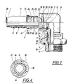
- Fig. 1 shows a partially sectioned side view of the coupling arrangement in accordance with the invention as a first illustrative embodiment with one coupling point in the separated state and with a second coupling point in the fully connected state
- Fig. 2 shows a corresponding view of the coupling arrangement in a partially connected state
- Fig. 3 shows a corresponding view of the arrangement in a fully connected state
- Fig. 4 shows a section through the coupling arrangement along the line IV-IV in Fig. 3.
- Figs. 5 and 6 show a partially sectioned view of the coupling arrangement in a second illustrative embodiment in a partially connected state and in a fully connected state respectively.
- the coupling arrangement in the first illustrative embodiment consists of three coupling components and is of the elbow coupling type, for example, for the connection of a hose 1 for pressurized medium at an angle to a pressure vessel which is not shown here.
- the three component parts of the coupling arrangement consist in the example illustrated of a first coupling component 2 in the form of a length of tube onto which is fitted the hose 1, a second coupling component 3 in the form of an elbow, and a third coupling component 4 in the form of a vessel-connecting component which exhibits an external threaded section 5 intended to be screwed into, for example, the wall of the aforementioned vessel.
- the coupling arrangement in accordance with the first illustrative embodiment exhibits two coupling points which are executed in a similar fashion in accordance with the invention.
- the first coupling point is arranged between the length of tube 2 and one end of the elbow 3.
- the elbow is executed at the aforementioned end in the form of a female component with a circular opening 6 which is transformed into an essentially cylindrical passage 7.
- the first coupling component 2 is executed at one of its ends in the form of a male component, so dimensioned as to be introduced into the open end 6 of the elbow 3.
- the opposite end of the length of tube 2 is executed with an attachment stub 8 exhibiting annular ridges 9 for holding one end of the hose 1 which has been pushed on.
- the other end of the length of tube 2 which serves as a male component is terminated by a stop flange 10, which also forms an end stop for the end 11 of the hose 1.
- the coupling arrangement exhibits in a conventional manner sealing elements for the purpose of providing a pressure-tight and dirt-protected connection between the coupling components.
- sealing elements consist primarily of an inner sealing ring 12 located in an annular groove 13 in the female component.
- the sealing ring 12 consists of an elastic 'O'-ring seal executed in an elastic material such as rubber or plastic.
- a further sealing element 14 is slid onto the male component 2 and makes contact with the stop flange 10. This seal primarily affords protection against the ingress of dirt and dust and is intended to provide a seal through making contact with the walls of an annular groove 15 at the open end of the female component.
- This sealing element 14 is thus also annular in form and is preferably executed in an elastic material such as rubber or plastic.
- the sealing element 14 may, for example, be of essentially rectangular cross section, whereas the inner sealing element 12 may with advantage exhibit circular or oval cross-sectional form.
- the coupling arrangement in accordance with the invention exhibits a locking arrangement 16 intended to lock the two coupling components securely together in the connected state.
- the locking arrangement exhibits a locking device 17 which is capable of being adjusted between a releasing and a locking position.
- the locking device 17 consists of a sprung locking ring, the form of which may best be appreciated from Fig. 4.
- the locking ring is so arranged as to be displaced between a radial first position, which in this first position is a radial inner position, and a radial second position, which is a radial outer position.
- the locking ring 17 is situated in a recess 18 in the female component with two contact surfaces 19, 20 which run parallel with one another, and each of which extends in its radial plane relative to the longitudinal axis 21 of the female component 3.
- the locking ring 17 is, as may be appreciated from Fig. 4, bent in the example shown into an oval form and is executed with ends 21 which point away from one another so as to facilitate withdrawal of the locking ring.
- the recess 18 is open laterally and perpendicularly to the plane of the paper in Fig. 1 so as to permit the locking ring 17 to be inserted and removed.
- the coupling component 2 exhibits at its front end a guide surface 22 with a conical surface so arranged, when the male component is introduced into the female component, as to displace the locking ring 17 from the locked position to the releasing position.
- a sealing surface 23 having essentially the form of a cylinder jacket, the diameter of which, with appropriate clearance, is rather less than the diameter of the cylinder jacket shaped surface 7 of the female component, but is greater than the internal diameter of the sealing ring 12.
- the sealing surface 23 in the form of a cylinder jacket is interrupted by two annular grooves 24, 25 in the male component, of which the rear annular groove 24 is a conventional locking groove intended to interact with the locking ring 17, said groove exhibiting in addition to a bottom having, for example, a surface in the form of a cylinder jacket, two transverse contact surfaces extending in different radial planes relative to the longitudinal axis 28 of the length of tube 2.
- the second locking groove 25 exhibits a contact surface 29 facing away from the end of the male component, that is to say away from the guide surface 22, which similarly extends essentially in a radial plane to the longitudinal axis 28, and an oblique, preferably conical guide surface 30, which is intended to guide the locking ring 17 into its releasing position.
- the other coupling point which is present between the elbow 3 and the vessel-connecting component 4 has a sealing and locking arrangement which completely matches the first coupling point.
- the coupling component of the elbow 3 which belongs to this second coupling point is instead executed as a male component 31, whilst the vessel-connecting component 4 exhibits a sleeve-shaped section 32 which forms the female component.
- Fig. 1 this coupling point is illustrated in the fully connected state with the vessel-connecting component 4 in the locked position relative to the elbow 3.
- the locking arrangement 16 is thus identical with the locking arrangement described above, as are the two annular sealing elements 12, 14.
- the vessel-connecting component 4 exhibits a further elastic 'O'-ring seal 33 to provide a seal against a wall (not shown here) and around the hole in the wall through which the threaded section 5 extends.
- a wall not shown here
- the second coupling point has been broken away in Figs. 2 and 3.
- the function of the coupling arrangement is now described with reference to the first illustrative embodiment and more specifically to the first coupling point, which is shown in three different positions in Figs. 1, 2 and 3.
- the two coupling components 1, 2 are connected together by introducing the male component into the female component of the elbow 3.
- the locking arrangement is now in its unexpanded position, that is to say in a radial inner position with the locking ring 17 exhibiting an identical form to that illustrated in Fig. 1.
- the locking ring 17 is thus in position inside the female component in the manner illustrated in Fig. 1, in which case the sealing element 12 is located in its groove 13 in the female component, whereas the sealing element 14 is in place on the male component.
- the latter element may even be positioned in the recess 15 at the open end of the female component.
- the length of tube 2 is introduced into the female component and makes contact with its oblique guide surface 22 with the locking ring 17, the latter will be caused to expand to a radial outer releasing position in which the locking ring with its two legs 34 will grip around the cylinder jacket-shaped surface 23 of the male component.
- the male component has been introduced into the intermediate position illustrated in Fig. 2 with the front locking groove 25 situated directly in line with the locking ring 17, the latter will be caused by its spring effect to snap into engagement in the locking groove.
- the locking ring 17 is, in fact, pre-tensioned in such a way that it constantly endeavours to adopt the radial inner locking position illustrated in Fig. 4.
- This intermediate position is an. effective locking position to the effect that the male component cannot be withdrawn due to the contact between the locking ring and the contact surface 29.
- the locking groove is situated at a distance from the guide surface 22 such that the cylinder jacket-shaped sealing surface 25 of the male component has not yet made contact with the locking element 13. Complete sealing has not, therefore, been achieved at the coupling point.
- the male component is advanced further into the female component for a certain distance, in conjunction with which the locking ring 17 will be caused to expand further through the effect of the oblique guide surface 30 of the locking groove until the male component has been introduced into the position illustrated in Fig. 3, where the rear locking groove 24 is directly in line with the locking ring 17, which thus snaps into engagement in the locking groove and adopts its completely locked position with the two coupling components completely connected together.
- the locking arrangement will now have adopted the position illustrated in Fig. 4. In this position the cylinder jacket-shaped surface 23 of the male component will have established contact with the sealing ring 13, against which complete sealing will be achieved; see Fig. 3.
- the dirt-excluding sealing ring 14 will also have come into sealing contact in the annular recess 15.
- the recess 18 exhibits a space to permit the necessary expansion of the legs 34 in a direction away from one another so as to enable the male component to be introduced.
- a recess 35 is provided in order to facilitate the removal of the locking ring by means of a screwdriver or similar so as to permit the dismantling of the coupling components.
- the coupling arrangement in accordance with the second illustrative embodiment otherwise consists of only two parts, that is to say a first coupling component 102 and a second coupling component 103, and constitutes a straight coupling in which the first coupling component consists of a length of tube onto which the hose 101 is pushed, and the second coupling component consists of a vessel-connecting component which corresponds essentially in its external construction to the third coupling component in accordance with the first embodiment.
- the first coupling component 102 similarly exhibits a stop flange 110 and an outer sealing element 114 which mainly affords protection against dirt and dust.
- the coupling arrangement also exhibits a locking arrangement 116 so arranged as to keep the two coupling components securely locked to one another in an inner, sealing, locked position in accordance with Fig. 6.
- the opposite construction of the second illustrative embodiment in accordance with Figs. 5 and 6 involves the locking device 117 of the locking arrangement being arranged in the male component, that is to say being supported by the first coupling component 102, whilst the two locking grooves 124, 125 are arranged in the female component, that is to say the second coupling component 103.
- the male component also exhibits an inner sealing ring 112 in the form of an elastic 'O'-ring seal, whilst the female component exhibits at its open end 106 a guide surface 122 executed with a conical surface.
- the two locking grooves 124, 125 are of identical design to the two locking grooves in accordance with the first illustrative embodiment, that is to say with one of the locking grooves exhibiting transverse contact surfaces 126, 127, each of which is situated in its own radial plane, whilst the other locking groove 125 exhibits a transverse contact surface 129 and a conical guide surface 130.
- the coupling device 117 is also executed in accordance with the second example as a sprung locking ring made of steel, for example, although in its unactuated initial position this is situated in a radial first or outer position and is so arranged as to be forced against the effect of its spring bias into a radial second or inner position.
- connection is entirely mechanical, and its function is released by separating the two coupling components 102, 103 one from the other so as to correspond with the position in accordance with Fig. 1.
- first coupling component 102 is introduced through the open end 106 of the second coupling component 103.
- the locking device 117 will now be brought into contact with the conical guide surface 122 at the open end 106 of the female component.
- the locking device 117 is forced in this way against the effect of its spring bias into its radial inner position after having passed over a cylinder jacket-shaped part 135 and a second conical guide surface 136 until the locking device 117 snaps into engagement in the first or front locking groove 125, in conjunction with which the locking device will be slightly sprung open. In this position the first coupling component cannot be withdrawn without performing some other action from the second coupling component because of the contact between the locking device 117 and the contact surface 129 in the first locking groove 125.
- the sealing element 112 will have been introduced through the open end 106 and will eventually come into tangential contact with the guide surface 122, which can produce a certain amount of stabilization of the first coupling component in the second coupling component, but which does not provide a seal against leakage of the medium which passes through the inside of the two coupling components as they are connected together.
- the two coupling components exhibit in a conventional manner transcurrent holes which together form a communicating passageway between parts of a pressurized medium system, for example a compressed air system. Once this outer, incomplete coupling position has been adopted, a hissing noise will be heard in the case of a gaseous medium indicating that complete connection does not exist.
- the first coupling component is now pushed further onto the second coupling component for a certain distance, when the locking device 117 will be permitted to leave the front locking groove 125 via its guide surface 130, which forces the locking device 117 into its radial inner position. Once the locking device reaches the second or rear locking groove 124, the locking device will snap into engagement in it. Complete connection and a locked position will now have taken place as a result of the locking device 117 having been arrested by the contact surfaces 126, 127.
- the first coupling component is now incapable of axial displacement in any direction, at the same time as complete sealing will have been achieved as a result of the compression of the sealing element 112 into sealing contact with the cylinder jacket-shaped sealing surface 135 of the second coupling component.
- the sealing eleMent 114 is slightly compressed and is in sealing contact with the guide surface 122 at the open end 106.
- Release of the two coupling components in accordance with the second illustrative embodiment is achieved in principle in the same manner as in the first illustrative embodiment by displacing the locking device 117, which in this way in accordance with the second illustrative embodiment will be compressed into its radial inner position in such a way that the contact surface 128 can be passed by the locking device in the further locking groove 124, with the position of the locking device similarly being maintained as it passes over the first locking groove 125, when the first locking component can be removed from the second locking component.
- an additional locking position is provided in the form of an intermediate position at which incomplete sealing is provided. It is possible to establish in this way, for example during subsequent inspections of the system when it is filled with the pressurized medium, for instance compressed air, which is to pass through the coupling, the extent to which the inner completely connected position or only the intermediate position illustrated in Fig. 2 has been adopted. This is easily determined by acoustical means by an inspector listening for the leakage of air.
- the pressurized medium for instance compressed air
- the male component may move in a direction outwards from the female component, although such movement can take place only as far as the intermediate position in which the locking arrangement will reliably snap into engagement and will prevent the coupling from becoming fully separated.
- the coupling arrangement in its connected state, that is to say both in the intermediate position and in the inner position, the coupling components will together form a transcurrent passageway for the pressurized medium in question because all the coupling components will exhibit transcurrent holes open at both ends.
- the invention is not restricted to the illustrative embodiment described above and portrayed in the drawings, but may be modified within the context of the following Patent Claims. It is conceivable, for example, for more than one locking ring to be present. It is also conceivable for the locking ring to be replaced by some other locking element capable of being displaced in a similar fashion between a locked position and a releasing position.
- the elbow may be replaced by a simple straight sleeve which, instead of being provided with a second coupling point, is provided with a thread for connection to a container or a component corresponding to the attachment tube 8 for the attachment of a hose or for the connection of a tube.
Landscapes
- Engineering & Computer Science (AREA)
- General Engineering & Computer Science (AREA)
- Mechanical Engineering (AREA)
- Transportation (AREA)
- Quick-Acting Or Multi-Walled Pipe Joints (AREA)
- Mechanical Operated Clutches (AREA)
- Hydraulic Clutches, Magnetic Clutches, Fluid Clutches, And Fluid Joints (AREA)
Applications Claiming Priority (1)
| Application Number | Priority Date | Filing Date | Title |
|---|---|---|---|
| SE8403328A SE459279B (sv) | 1984-06-21 | 1984-06-21 | Kopplingsanordning vid tryckmediumledningar |
Publications (2)
| Publication Number | Publication Date |
|---|---|
| EP0226689A1 true EP0226689A1 (de) | 1987-07-01 |
| EP0226689B1 EP0226689B1 (de) | 1991-07-31 |
Family
ID=20356315
Family Applications (1)
| Application Number | Title | Priority Date | Filing Date |
|---|---|---|---|
| EP85850410A Expired - Lifetime EP0226689B1 (de) | 1984-06-21 | 1985-12-20 | Kupplungseinrichtung für unter Druck stehende Fluidumleitungen |
Country Status (4)
| Country | Link |
|---|---|
| US (1) | US4707000A (de) |
| EP (1) | EP0226689B1 (de) |
| DE (1) | DE3583686D1 (de) |
| SE (1) | SE459279B (de) |
Cited By (22)
| Publication number | Priority date | Publication date | Assignee | Title |
|---|---|---|---|---|
| EP0748975A1 (de) * | 1995-06-17 | 1996-12-18 | Armaturenfabrik Hermann Voss GmbH + Co. | Steckkupplung für Druckmittelsysteme |
| EP0751332A1 (de) * | 1995-06-30 | 1997-01-02 | Armaturenfabrik Hermann Voss GmbH + Co. | Steckkupplung für Druckmittelsysteme |
| EP0751330A1 (de) * | 1995-06-30 | 1997-01-02 | Armaturenfabrik Hermann Voss GmbH + Co. | Steckkupplung für Druckmittelsysteme |
| EP0751331A1 (de) * | 1995-06-30 | 1997-01-02 | Armaturenfabrik Hermann Voss GmbH + Co. | Steckkupplung für Druckmittelsysteme |
| EP0753698A1 (de) * | 1995-07-08 | 1997-01-15 | Armaturenfabrik Hermann Voss GmbH + Co. | Steckverbindung zum Anschluss von Druckmittelleitungen |
| GB2302926A (en) * | 1995-06-30 | 1997-02-05 | Valeo | Feed connection device for a fluid pressure system and a hydraulic cylinder for controlling a clutch provided with such a device |
| EP0758066A1 (de) * | 1995-08-08 | 1997-02-12 | Armaturenfabrik Hermann Voss GmbH + Co. | Steckkupplung für Druckmittelsysteme |
| EP0766033A1 (de) * | 1995-09-29 | 1997-04-02 | Armaturenfabrik Hermann Voss GmbH + Co. | Steckkupplung für Druckmittelsysteme |
| WO1997013094A1 (en) * | 1995-10-03 | 1997-04-10 | Raufoss Technology A/S | Coupling for pressurized medium |
| EP0813017A2 (de) * | 1996-06-14 | 1997-12-17 | Armaturenfabrik Hermann Voss GmbH + Co. | Steckkupplung für Druckmittelsysteme |
| US6027144A (en) * | 1996-09-20 | 2000-02-22 | Armaturenfabrik Hermann Voss Gmbh + Co. | Plug-in connector for pressure medium systems |
| DE19623995B4 (de) * | 1996-06-15 | 2004-07-15 | Voss Automotive Gmbh | Steckkupplung für Druckmittelsysteme |
| EP1495254A2 (de) * | 2001-02-21 | 2005-01-12 | Parker Hannifin Corporation | Flüssigkeitskupplungsstecker |
| FR2873186A1 (fr) * | 2004-07-19 | 2006-01-20 | Parker Hannifin France Sas Soc | Raccord pour conduit de fluides hydrauliques ou pneumatiques |
| DE19848489B4 (de) * | 1998-10-21 | 2006-01-26 | Johannes Schäfer vorm. Stettiner Schraubenwerke GmbH & Co. KG | Lösbare Steckverbindung für den Anschluß von Rohrleitungen |
| EP1770320A1 (de) * | 2005-09-29 | 2007-04-04 | Johannes Schäfer vormals Stettiner Schraubenwerke GmbH & Co. KG | Lösbare Steckverbindung für Rohrleitungen |
| WO2010006838A1 (de) * | 2008-07-14 | 2010-01-21 | Voss Automotive Gmbh | Steckkupplung für druckmittel-leitungen |
| AT509195A4 (de) * | 2010-03-12 | 2011-07-15 | Henn Gmbh & Co Kg | Verfahren zum verbinden eines endabschnitts einer leitung für flüssige oder gasförmige medien mit einem steckverbinder |
| AT509196B1 (de) * | 2010-03-12 | 2011-07-15 | Henn Gmbh & Co Kg | Verfahren zum verbinden eines endabschnitts einer leitung für flüssige oder gasförmige medien mit einem steckverbinder |
| US8287006B2 (en) | 2007-11-28 | 2012-10-16 | Kongsberg Automotive As | Tube coupling system for a pressurised fluid system |
| WO2015104073A1 (de) * | 2014-01-10 | 2015-07-16 | Oetiker Schweiz Ag | Schnellkupplung mit verriegelungsanzeige |
| WO2023138760A1 (en) * | 2022-01-19 | 2023-07-27 | Ka Group Ag | Releasable port connection assembly |
Families Citing this family (48)
| Publication number | Priority date | Publication date | Assignee | Title |
|---|---|---|---|---|
| US4884829A (en) * | 1986-09-16 | 1989-12-05 | Johannes Schaefer Vorm. Stettiner Schraubenwerke Gmbh & Co. Kg | Plug-in connection for connecting tube and host lines in particular for use in tube-line systems of motor vehicles |
| US4813716A (en) * | 1987-04-21 | 1989-03-21 | Titeflex Corporation | Quick connect end fitting |
| US4804206A (en) * | 1987-10-13 | 1989-02-14 | Dover Corporation | Swivel construction and method of making the same |
| US4875709A (en) * | 1988-02-26 | 1989-10-24 | Caroll James E | Controlled leak path |
| US4832378A (en) * | 1988-04-04 | 1989-05-23 | Dura Power Systems Division Of Wickes Manufacturing Company | Fluid duct coupling and snap clip therefor |
| JPH0629581Y2 (ja) * | 1989-11-06 | 1994-08-10 | 株式会社トヨックス | 蛇口用ホース継手 |
| GB2245670A (en) * | 1990-06-27 | 1992-01-08 | Ford Motor Co | A pipe coupling |
| US5215337A (en) * | 1991-03-14 | 1993-06-01 | Spirkowyc Paul A | Containment piping system with expansion seal |
| US5152555A (en) * | 1991-03-26 | 1992-10-06 | Itt Corporation | Quick connect insertion indicator clip |
| ES2071450T3 (es) * | 1991-04-29 | 1995-06-16 | Caillau Ets | Elemento de conexion para el empalme rapido de un tubo. |
| EP0522820A1 (de) * | 1991-07-05 | 1993-01-13 | David A Barker | Drehkupplung |
| DK137593D0 (da) * | 1993-12-09 | 1993-12-09 | Micro Matic As | Spaerrearrangement |
| US5402643A (en) * | 1993-12-10 | 1995-04-04 | Cummins Engine Company, Inc. | Flexible oil drain tube for turbocharger |
| US5472242A (en) * | 1994-06-24 | 1995-12-05 | Petersen; Horst U. | End-fitting for pipe connection having proper insertion indicator |
| US5490694A (en) * | 1995-03-03 | 1996-02-13 | American Fence Corp | Threadless pipe coupler |
| US5671955A (en) * | 1995-06-09 | 1997-09-30 | American Fence Corporation | Threadless pipe coupler for sprinkler pipe |
| BR9601539A (pt) * | 1996-04-12 | 2004-06-29 | Tampas Click Ltda | Indicador de montagem e conexão de linhas de combustìveis ou fluìdos em geral |
| US5707085A (en) * | 1996-09-12 | 1998-01-13 | General Motors Corporation | Fluid coupling |
| GB9620011D0 (en) * | 1996-09-25 | 1996-11-13 | Bend All Mfg Inc | Snap-in end fitting for pipes |
| US6119544A (en) * | 1996-12-03 | 2000-09-19 | Fico Cables, S.A. | Control half-cable linking device |
| DE19705167C5 (de) * | 1997-02-11 | 2006-11-02 | Johannes Schäfer vorm. Stettiner Schraubenwerke GmbH & Co. KG | Steckverbindung für Rohrleitungen |
| DE19715293B4 (de) * | 1997-02-11 | 2005-06-02 | Johannes Schäfer vorm. Stettiner Schraubenwerke GmbH & Co. KG | Steckverbindung für Rohrleitungen |
| US5918914A (en) * | 1997-11-25 | 1999-07-06 | Morris; Waldo Ivan | Sealing lock joint pipe fitting |
| DE50007422D1 (de) † | 1999-03-04 | 2004-09-23 | Schaefer Stettiner Schrauben | Lösbare Steckverbindung für den Anschluss von Rohrleitungen |
| US6286877B1 (en) * | 2000-04-17 | 2001-09-11 | Anthony Manufacturing Corp. Industrial Prod. Div. | Dual seal pipe coupling |
| DE10022085C1 (de) * | 2000-05-08 | 2001-09-20 | Schaefer Stettiner Schrauben | Schnellkupplung zum Verbinden von Medienleitungen |
| DE20009634U1 (de) * | 2000-05-29 | 2000-08-24 | Armaturenfabrik Hermann Voss GmbH & Co., 51688 Wipperfürth | Steckkupplung für Druckmittelsysteme |
| KR100599639B1 (ko) * | 2001-03-09 | 2006-07-12 | 더 게이츠 코포레이션 | 신속 연결 커플링 |
| SE520508C2 (sv) | 2001-11-15 | 2003-07-15 | Volvo Lastvagnar Ab | Kopplingsanordning för tryckmediumledningar och förfarande för framställning av sådan kopplingsanordning, innefattande läckagespår för indikering av läckage |
| US20030173775A1 (en) * | 2002-03-15 | 2003-09-18 | Mclanahan Corporation | Sand tank discharge elbow |
| TW549389U (en) * | 2002-09-10 | 2003-08-21 | Ming-Shiun Jian | Pipe coupler |
| ES2239539B1 (es) * | 2004-03-09 | 2006-04-01 | Manufactura Moderna De Metales, S.A. | Dispositivo de conexion rapida para conductos de automoviles. |
| BRPI0517505B1 (pt) * | 2004-10-29 | 2022-04-19 | The Gates Corporation | Acoplamento de conexão rápida e método para inserção |
| DE102006016211A1 (de) * | 2006-04-03 | 2007-10-04 | Novalung Gmbh | Kupplung für rohrförmige Elemente |
| US7497480B2 (en) * | 2006-04-07 | 2009-03-03 | Ti Group Automotive Systems, Llc | Hybrid quick connector |
| DE102008014413B4 (de) * | 2008-03-14 | 2017-12-14 | Festo Ag & Co. Kg | Ventil |
| FR2929679B1 (fr) * | 2008-04-07 | 2010-04-23 | Raymond A & Cie | Raccord de connecteur pour conduits de fluide avec un ressort en fil metallique |
| DE202008009398U1 (de) | 2008-07-14 | 2009-11-19 | Voss Automotive Gmbh | Steckkupplung für Druckmittel-Leitungen |
| DE202008009399U1 (de) | 2008-07-14 | 2009-11-19 | Voss Automotive Gmbh | Steckkupplung für Druckmittel-Leitungen |
| US8851526B2 (en) * | 2012-01-11 | 2014-10-07 | GM Global Technology Operations LLC | Cap for a quick connect fitting assembly and method of assembly using same |
| WO2014152139A1 (en) * | 2013-03-15 | 2014-09-25 | Flowserve Management Company | Sanitary fitting for fluid handling equipment |
| US10113676B2 (en) * | 2014-02-25 | 2018-10-30 | Sdb Ip Holdings, Llc | Clip for adjustable pipe fitting |
| US9845908B2 (en) * | 2015-03-31 | 2017-12-19 | Ap Couplings, Inc. | Lightweight quick connector system |
| DE102015111895A1 (de) * | 2015-07-22 | 2017-01-26 | Dr. Ing. H.C. F. Porsche Aktiengesellschaft | Fahrzeugkomponente und Kraftfahrzeug |
| US10473243B2 (en) * | 2016-01-26 | 2019-11-12 | Tectran Mfg. Inc. | Hose repair kit with live swivel coupling |
| US9869416B2 (en) * | 2016-01-26 | 2018-01-16 | Tectran Mfg. Inc. | Swivel coupling and hose assemblies and kits utilizing the same |
| US10711876B1 (en) * | 2019-10-28 | 2020-07-14 | Saptfc Holding, Llc | Reinforcement sealing tubes for stabilizing a housing in an automobile transmission |
| US20220186860A1 (en) * | 2020-12-10 | 2022-06-16 | Fumoto Giken Co., Ltd. | Joint |
Citations (3)
| Publication number | Priority date | Publication date | Assignee | Title |
|---|---|---|---|---|
| EP0014094A1 (de) * | 1979-01-24 | 1980-08-06 | Crossley & Davenport Limited | Kupplungsvorrichtung |
| GB2099945A (en) * | 1981-06-05 | 1982-12-15 | Dril Quip Inc | Pipe connector |
| FR2511115A1 (fr) * | 1981-08-07 | 1983-02-11 | Staubli Sa Ets | Perfectionnements aux raccords rapides pour la jonction amovible des canalisations |
Family Cites Families (2)
| Publication number | Priority date | Publication date | Assignee | Title |
|---|---|---|---|---|
| US3574359A (en) * | 1969-07-22 | 1971-04-13 | Gen Motors Corp | Fluid conduit coupling |
| AU5688680A (en) * | 1979-04-16 | 1980-10-23 | Chemetron Corp. | Pile joint |
-
1984
- 1984-06-21 SE SE8403328A patent/SE459279B/sv not_active IP Right Cessation
-
1985
- 1985-12-20 DE DE8585850410T patent/DE3583686D1/de not_active Expired - Lifetime
- 1985-12-20 US US06/811,772 patent/US4707000A/en not_active Expired - Lifetime
- 1985-12-20 EP EP85850410A patent/EP0226689B1/de not_active Expired - Lifetime
Patent Citations (3)
| Publication number | Priority date | Publication date | Assignee | Title |
|---|---|---|---|---|
| EP0014094A1 (de) * | 1979-01-24 | 1980-08-06 | Crossley & Davenport Limited | Kupplungsvorrichtung |
| GB2099945A (en) * | 1981-06-05 | 1982-12-15 | Dril Quip Inc | Pipe connector |
| FR2511115A1 (fr) * | 1981-08-07 | 1983-02-11 | Staubli Sa Ets | Perfectionnements aux raccords rapides pour la jonction amovible des canalisations |
Cited By (32)
| Publication number | Priority date | Publication date | Assignee | Title |
|---|---|---|---|---|
| EP0748975A1 (de) * | 1995-06-17 | 1996-12-18 | Armaturenfabrik Hermann Voss GmbH + Co. | Steckkupplung für Druckmittelsysteme |
| GB2302926B (en) * | 1995-06-30 | 1999-03-24 | Valeo | A feed connection device for a fluid pressure system |
| EP0751332A1 (de) * | 1995-06-30 | 1997-01-02 | Armaturenfabrik Hermann Voss GmbH + Co. | Steckkupplung für Druckmittelsysteme |
| EP0751330A1 (de) * | 1995-06-30 | 1997-01-02 | Armaturenfabrik Hermann Voss GmbH + Co. | Steckkupplung für Druckmittelsysteme |
| EP0751331A1 (de) * | 1995-06-30 | 1997-01-02 | Armaturenfabrik Hermann Voss GmbH + Co. | Steckkupplung für Druckmittelsysteme |
| GB2302926A (en) * | 1995-06-30 | 1997-02-05 | Valeo | Feed connection device for a fluid pressure system and a hydraulic cylinder for controlling a clutch provided with such a device |
| EP0753698A1 (de) * | 1995-07-08 | 1997-01-15 | Armaturenfabrik Hermann Voss GmbH + Co. | Steckverbindung zum Anschluss von Druckmittelleitungen |
| EP0758066A1 (de) * | 1995-08-08 | 1997-02-12 | Armaturenfabrik Hermann Voss GmbH + Co. | Steckkupplung für Druckmittelsysteme |
| EP0766033A1 (de) * | 1995-09-29 | 1997-04-02 | Armaturenfabrik Hermann Voss GmbH + Co. | Steckkupplung für Druckmittelsysteme |
| WO1997013094A1 (en) * | 1995-10-03 | 1997-04-10 | Raufoss Technology A/S | Coupling for pressurized medium |
| US5845944A (en) * | 1995-10-03 | 1998-12-08 | Raufoss Technology A/S | Coupling for pressurized medium |
| EP0813017A2 (de) * | 1996-06-14 | 1997-12-17 | Armaturenfabrik Hermann Voss GmbH + Co. | Steckkupplung für Druckmittelsysteme |
| EP0813017A3 (de) * | 1996-06-14 | 1998-11-11 | Armaturenfabrik Hermann Voss GmbH + Co. | Steckkupplung für Druckmittelsysteme |
| DE19623995B4 (de) * | 1996-06-15 | 2004-07-15 | Voss Automotive Gmbh | Steckkupplung für Druckmittelsysteme |
| US6027144A (en) * | 1996-09-20 | 2000-02-22 | Armaturenfabrik Hermann Voss Gmbh + Co. | Plug-in connector for pressure medium systems |
| DE19848489B4 (de) * | 1998-10-21 | 2006-01-26 | Johannes Schäfer vorm. Stettiner Schraubenwerke GmbH & Co. KG | Lösbare Steckverbindung für den Anschluß von Rohrleitungen |
| EP1495254A2 (de) * | 2001-02-21 | 2005-01-12 | Parker Hannifin Corporation | Flüssigkeitskupplungsstecker |
| EP1495254A4 (de) * | 2001-02-21 | 2009-07-22 | Parker Hannifin Corp | Flüssigkeitskupplungsstecker |
| FR2873186A1 (fr) * | 2004-07-19 | 2006-01-20 | Parker Hannifin France Sas Soc | Raccord pour conduit de fluides hydrauliques ou pneumatiques |
| EP1770320A1 (de) * | 2005-09-29 | 2007-04-04 | Johannes Schäfer vormals Stettiner Schraubenwerke GmbH & Co. KG | Lösbare Steckverbindung für Rohrleitungen |
| US8287006B2 (en) | 2007-11-28 | 2012-10-16 | Kongsberg Automotive As | Tube coupling system for a pressurised fluid system |
| WO2010006838A1 (de) * | 2008-07-14 | 2010-01-21 | Voss Automotive Gmbh | Steckkupplung für druckmittel-leitungen |
| CN103032644B (zh) * | 2008-07-14 | 2015-05-13 | 福士汽车配套部件责任有限公司 | 用于压力介质导管的插塞式连接装置 |
| CN103032644A (zh) * | 2008-07-14 | 2013-04-10 | 福士汽车配套部件责任有限公司 | 用于压力介质导管的插塞式连接装置 |
| AT509195B1 (de) * | 2010-03-12 | 2011-07-15 | Henn Gmbh & Co Kg | Verfahren zum verbinden eines endabschnitts einer leitung für flüssige oder gasförmige medien mit einem steckverbinder |
| AT509196A4 (de) * | 2010-03-12 | 2011-07-15 | Henn Gmbh & Co Kg | Verfahren zum verbinden eines endabschnitts einer leitung für flüssige oder gasförmige medien mit einem steckverbinder |
| AT509196B1 (de) * | 2010-03-12 | 2011-07-15 | Henn Gmbh & Co Kg | Verfahren zum verbinden eines endabschnitts einer leitung für flüssige oder gasförmige medien mit einem steckverbinder |
| AT509195A4 (de) * | 2010-03-12 | 2011-07-15 | Henn Gmbh & Co Kg | Verfahren zum verbinden eines endabschnitts einer leitung für flüssige oder gasförmige medien mit einem steckverbinder |
| WO2015104073A1 (de) * | 2014-01-10 | 2015-07-16 | Oetiker Schweiz Ag | Schnellkupplung mit verriegelungsanzeige |
| RU2623132C1 (ru) * | 2014-01-10 | 2017-06-22 | Отикер Швайц Аг | Быстроразъёмная муфта |
| US9816654B2 (en) | 2014-01-10 | 2017-11-14 | Oetiker Schweiz Ag | Rapid coupling |
| WO2023138760A1 (en) * | 2022-01-19 | 2023-07-27 | Ka Group Ag | Releasable port connection assembly |
Also Published As
| Publication number | Publication date |
|---|---|
| DE3583686D1 (de) | 1991-09-05 |
| SE8403328L (sv) | 1985-12-22 |
| SE8403328D0 (sv) | 1984-06-21 |
| SE459279B (sv) | 1989-06-19 |
| US4707000A (en) | 1987-11-17 |
| EP0226689B1 (de) | 1991-07-31 |
Similar Documents
| Publication | Publication Date | Title |
|---|---|---|
| EP0226689B1 (de) | Kupplungseinrichtung für unter Druck stehende Fluidumleitungen | |
| US5791698A (en) | Plastic pipe coupler with internal sealer | |
| US5692785A (en) | Plastic pipe coupler with internal sealer | |
| EP0100326B1 (de) | Fluidkupplung und herstellungsverfahren | |
| EP0870146B1 (de) | Schlauchkupplungsvorrichtung | |
| US4627644A (en) | Arrangement for a push-in coupling | |
| US4863202A (en) | Fluid connector assembly | |
| JP3077817B2 (ja) | 樹脂管の外周面係合用継手 | |
| US4290615A (en) | Butterfly valve | |
| US4570980A (en) | Staple coupling | |
| US3972547A (en) | Locking and nonseal joint device | |
| JP3350552B2 (ja) | チューブを継手に連結する装置 | |
| SK15112001A3 (sk) | Fiting alebo armatúra | |
| KR900013238A (ko) | 세경 배관 접속용 커넥터 | |
| JPS58109791A (ja) | ホ−ス継手 | |
| KR960006181B1 (ko) | 가는 관 접속용 커넥터 | |
| KR101779086B1 (ko) | 웨지 밀폐형 원터치 배관 커플러 | |
| EP0009368A1 (de) | Rohrkupplungsmuffe und Rohrverbindung | |
| CA1300661C (en) | Quick connect coupling | |
| EP0014094A1 (de) | Kupplungsvorrichtung | |
| KR20190018858A (ko) | 신축 가능한 파이프 연결구조체 | |
| JPH0125839Y2 (de) | ||
| WO1994015131A1 (en) | Connectors | |
| JPS6220436B2 (de) | ||
| JPH03129192A (ja) | 管継手構造 |
Legal Events
| Date | Code | Title | Description |
|---|---|---|---|
| PUAI | Public reference made under article 153(3) epc to a published international application that has entered the european phase |
Free format text: ORIGINAL CODE: 0009012 |
|
| AK | Designated contracting states |
Kind code of ref document: A1 Designated state(s): DE FR GB IT SE |
|
| 17P | Request for examination filed |
Effective date: 19871208 |
|
| 17Q | First examination report despatched |
Effective date: 19890105 |
|
| GRAA | (expected) grant |
Free format text: ORIGINAL CODE: 0009210 |
|
| AK | Designated contracting states |
Kind code of ref document: B1 Designated state(s): DE FR GB IT SE |
|
| PG25 | Lapsed in a contracting state [announced via postgrant information from national office to epo] |
Ref country code: SE Effective date: 19910731 |
|
| REF | Corresponds to: |
Ref document number: 3583686 Country of ref document: DE Date of ref document: 19910905 |
|
| ITF | It: translation for a ep patent filed | ||
| ET | Fr: translation filed | ||
| PLBE | No opposition filed within time limit |
Free format text: ORIGINAL CODE: 0009261 |
|
| STAA | Information on the status of an ep patent application or granted ep patent |
Free format text: STATUS: NO OPPOSITION FILED WITHIN TIME LIMIT |
|
| 26N | No opposition filed | ||
| REG | Reference to a national code |
Ref country code: GB Ref legal event code: IF02 |
|
| PGFP | Annual fee paid to national office [announced via postgrant information from national office to epo] |
Ref country code: FR Payment date: 20031210 Year of fee payment: 19 |
|
| PGFP | Annual fee paid to national office [announced via postgrant information from national office to epo] |
Ref country code: GB Payment date: 20031217 Year of fee payment: 19 |
|
| PGFP | Annual fee paid to national office [announced via postgrant information from national office to epo] |
Ref country code: DE Payment date: 20040102 Year of fee payment: 19 |
|
| PG25 | Lapsed in a contracting state [announced via postgrant information from national office to epo] |
Ref country code: GB Free format text: LAPSE BECAUSE OF NON-PAYMENT OF DUE FEES Effective date: 20041220 |
|
| PG25 | Lapsed in a contracting state [announced via postgrant information from national office to epo] |
Ref country code: DE Free format text: LAPSE BECAUSE OF NON-PAYMENT OF DUE FEES Effective date: 20050701 |
|
| GBPC | Gb: european patent ceased through non-payment of renewal fee |
Effective date: 20041220 |
|
| PG25 | Lapsed in a contracting state [announced via postgrant information from national office to epo] |
Ref country code: FR Free format text: LAPSE BECAUSE OF NON-PAYMENT OF DUE FEES Effective date: 20050831 |
|
| REG | Reference to a national code |
Ref country code: FR Ref legal event code: ST |