EP0224366B1 - Verfahren und Vorrichtung zur Verwandlung und Verarbeitung von Fernsehsignalen - Google Patents
Verfahren und Vorrichtung zur Verwandlung und Verarbeitung von Fernsehsignalen Download PDFInfo
- Publication number
- EP0224366B1 EP0224366B1 EP86308926A EP86308926A EP0224366B1 EP 0224366 B1 EP0224366 B1 EP 0224366B1 EP 86308926 A EP86308926 A EP 86308926A EP 86308926 A EP86308926 A EP 86308926A EP 0224366 B1 EP0224366 B1 EP 0224366B1
- Authority
- EP
- European Patent Office
- Prior art keywords
- signals
- digital data
- component video
- data signals
- component
- Prior art date
- Legal status (The legal status is an assumption and is not a legal conclusion. Google has not performed a legal analysis and makes no representation as to the accuracy of the status listed.)
- Expired - Lifetime
Links
Images


Classifications
-
- H—ELECTRICITY
- H04—ELECTRIC COMMUNICATION TECHNIQUE
- H04N—PICTORIAL COMMUNICATION, e.g. TELEVISION
- H04N5/00—Details of television systems
- H04N5/14—Picture signal circuitry for video frequency region
- H04N5/20—Circuitry for controlling amplitude response
- H04N5/205—Circuitry for controlling amplitude response for correcting amplitude versus frequency characteristic
-
- H—ELECTRICITY
- H04—ELECTRIC COMMUNICATION TECHNIQUE
- H04N—PICTORIAL COMMUNICATION, e.g. TELEVISION
- H04N9/00—Details of colour television systems
- H04N9/79—Processing of colour television signals in connection with recording
- H04N9/80—Transformation of the television signal for recording, e.g. modulation, frequency changing; Inverse transformation for playback
- H04N9/804—Transformation of the television signal for recording, e.g. modulation, frequency changing; Inverse transformation for playback involving pulse code modulation of the colour picture signal components
Definitions
- the present invention relates to a method of and apparatus for converting and processing a television signal suited for a high-definition television signal.
- HD video signal high-definition television signal
- NTSC system video signals for the current standard systems
- a digital recording system is preferred because it provides high quality of reproduced image and causes, in dubbing, small deterioration in the image quality.
- the bandwidths and sampling frequencies required for recording the HD video signal become as large, for example, as the following (1) video signal bandwidths Y 25.0MHz C w 12.5MHz C N 12.5MHz (2) sampling frequencies Y 64.8MHz C W 32.4MHz C N 32.4MHz
- the data rate of the digital data in such specification becomes 1037MB/s, which is extremely high as compared with the case of the so-called 4-2-2 type of digital VTR (sampling frequency: 13.5MHz) in the current standard system (NTSC system). Even in the case where parallel recording through four channels is practised, for example, the data rate for each channel exceeds 250MHz. Thus, there was a problem that it was very difficult to manufacture a magnetic head system capable of such high speed recording and circuit devices used for the signal processing system to process the signal to be supplied to such a magnetic head.
- the high-speed data signals obtained by sampling the broadband video signals such as the aforementioned high-resolution video signals can be converted into low-speed data signals.
- the high-speed data signals corresponding to the displayed picture are vertically divided into N sections wherein N is an integer larger than 2 and the frequencies of the divided data signals are frequency-converted by 1/N and transferred through N-channel transmission lines for subsequent image processing.
- US-A-4,456,930 discloses a low definition digital video signal in which the components of the signal are temporally divided and distributed among a plurality of tracks for recording.
- a method of converting and processing a plurality of digital data signals which comprise first, second and third component video signals, the method comprising the steps of: spatially dividing each of said digital data signals corresponding to the displayed picture into N sections thereof, wherein N is an integer larger than 2; expanding the divided digital data signals to have a period N times the period of the clock frequency of said digital data signals to produce divided and expanded digital data signals; and distributing each of the divided and expanded digital data signals into a respective set of two channels of transmission lines by disposing data of said first component video signal in said two channels of transmission lines alternately and with a sample space therebetween; and discarding alternate data of each of said second and third component video signals and transmitting the remaining alternate data of said second and third component video signals alternately during those sample spaces not occupied by said first component video signal of each of the transmission lines.
- apparatus for converting and processing a plurality of digital data signals which comprise first, second and third component video signals characterised in that it comprises means for spatially dividing each of said digital data signals corresponding to the displayed picture into N sections thereof, wherein N is an integer larger than 2; means for expanding each of the divided digital data signals to have a period N times the period of the clock frequency of said digital data signals; and means for distributing each of the divided and expanded digital data signals from said expanding means into a respective set two channels of transmission lines; said distributing means comprising means for disposing said first component video signal in said two channels of transmission lines alternately and with a sample space; and means for discarding alternate data samples of each of said second and third component video signals and means for transmitting the remaining alternate data samples of said second and third component video signals during the sample spaces not occupied by said first video signal of each of the transmission lines alternately.
- the invention is equal applicable to video signals in colour-difference and R-G-B formats.
- a luminance component signal Y and chrominance component signals C W and C N are supplied to an analog/digital converter 1.
- the frequency bandwidths of the signals Y, C W , and C N are, for example, 25 MHz, 12.5 MHz, and 12.5 MHz, respectively, as described above, which are sampled in the analog/digital converter 1 at 64.8 MHz, 32.4 MHz, and 32.4 MHz, respectively, where the quantization number of each sample is 8 bits.
- the signals Y, C W , and C N which are digitized in the analog/digital converter 1 are all supplied to an image area dividing circuit (parallel dividing circuit) 2.
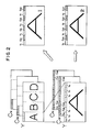
- This image area dividing circuit 2 is used for dividing each of the signals Y, C W and C N into equal intervals in the horizontal direction on the television screen as shown in Figure 2.
- Each signal is divided into four sections in the present embodiment.
- four signal processing portions 10, 20, 30 and 40 are provided in parallel, and the outputs of the image area dividing circuit 2 are supplied to their respective signal processing portions 10 - 40.
- the signal processing portions 10 - 40 are all of the same structure, the first signal processing portion 10 only will be described and illustrated and illustration and description of detailed structure of the second to fourth signal processing portions 20 - 40 will be omitted here.
- a signal processing portion 10 includes a data distributing circuit 11, which distributes data of the divided signals Y, C W , and C N supplied from the image area dividing circuits 2 to two error-correcting code encoding circuits 12a and 12b. By this distribution, there are formed two channels in the signal processing portion 10. Output of both of the error-correcting code encoding circuits 12a and 12b are supplied through a shuffling circuit 13 common to all the signal processing portions 10 - 40 to modulator circuits 14a and 14b and modulated therein, for example, by the scramble NRZ system. The outputs of both of the modulators 14a and 14b are converted into serial data in parallel/serial converters 15a and 15b, respectively, and supplied to electricity/light conversion elements 16a and 16b.
- the optical outputs from the electricity/light conversion elements 16a and 16b are supplied through optical fibers OF, respectively, to light/electricity conversion elements 51a and 51b of a recording head portion 50 to be converted therein back to electrical signals. It should be noted here that interference by mixing in of electrical noise specifically in the high frequency domain is prevented by the use of the optical transmission line.
- the outputs of the electricity/light converting elements 51a and 51b are supplied through amplifiers for recording 52a and 52b to recording magnetic heads H1 and H2.
- the second, third and fourth signal processing portions 20, 30 and 40 are connected through optical fibers with the second, third and fourth recording head portions 60, 70 and 80, and the recording head portions 60 - 80 include two recording heads H3, H4; H5, H6; and H7, H8, respectively.
- the four recording magnetic heads H1, H2, H3 and H4 are formed integrally with one another and the four recording magnetic heads H5 , H6, H7 and H8 are also formed integrally with one another and these two head groups are attached to a rotating drum at an angle of 180°. Since a magnetic tape (a metallic tape, for example) is wrapped around the drum at a wrapping angle of approximately 330°, eight tracks are simultaneously recorded by both of the head groups; it is arranged such that 16 tracks correspond to one field period.
- a magnetic tape a metallic tape, for example
- the mechanism of the digital VTR of the present embodiment is based upon the format type C and the speed of revolution of the drum is arranged to be 7200 rpm.
- a one inch wide tape travels at the speed of approximately 800 mm/s, and a 14-inch (35.56 cm) reel for three-hour play for a VTR of the format type C can be used for 1.5 hours of recording or playback.
- the sampling frequency for the output therefrom is reduced to 16.2 MHz, 1/4 of the previously mentioned 64.8 MHz. Details of the parallel dividing process in the image area dividing circuit 2 will be described later. For the sake of simplicity, it is assumed here that there are present eight pieces of data on one scanning line of each of the divided screens for the signals Y, C W and C N as shown in Figure 2.
- the data Y1, Y3, Y5 and Y7 in odd-numbered places of the signal Y are distributed to the error-correcting code encoding circuit 12a of one of the channels and the data Y2, Y4, Y6 and Y8 in the even-numbered places are distributed to the error-correcting code encoding circuit 12b of the other channel.
- C W2 , C W4 , C W6 and C W8 , and C N2 , C N4 , C N6 and C N8 in the even-numbered places, for example, are discarded, and C W1 , C N1 , C W5 and C N5 are distributed to one channel, and C W3 , C N3 , C W7 and C N7 are distributed to the other channel, and thus, the luminance data at each sample point and the chrominance data in its vicinity are adapted to be uniformly distributed.
- the sampling frequency of the data from the input to the data distributing circuit 11 to the output of the modulators 14a and 14b is 16.2 MHz as previously described, and the circuit devices for processing signals at such a sampling frequency are easily obtained by adaption to this purpose of the circuit devices for digital VTR of the current standard system (PAL or NTSC system) or the like.
- the data in each of the channels are encoded to Reed-Solomon product codes in the error-correcting code encoding circuits 12a and 12b and are converted by the parallel/serial converters 15a and 15b into serial data at 129.6 MB/s data rate.
- a magnetic head capable of recording data at such a data rate can be manufactured using the current magnetic head technique without much difficulty.
- the signal processing portions 10 - 40 supplied with the outputs of the image area dividing circuit 2 are each provided with a data distributing circuit 11, etc, whereby each of the signal processing portions 10 - 40 and the recording head portions 50 - 80 serially connected thereto is arranged in two channels so that in total eight channels of parallel transmission system are provided. Therefore, the data rate transferred through each channel has been enabled to be reduced and recording (transfer) of digital data of the HD video signal has been made easy.
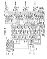
- the image area dividing circuit 2 in use for an embodiment of the present invention will be described below with reference to Figure 3.
- the circuit of Figure 3 is separately provided for each of the digital luminance signal and the digital chrominance signals C W and C N .
- Eight bit parallel data (B, D in Figure 4) of the digital video signal (the luminance component signal Y or digital chrominance component signal C W or C N ) from the analog/digital converter 1 of the digital VTR of Figure 1 is supplied to a shift register 260. Since the digital video signal for one screen is made up of 2000 samples in the horizontal direction and 1050 lines in the vertical direction, and this digital video signal is equally divided into four sections for each line, 500 samples each thereof will be sequentially called the first - fourth series, (1) - (4).
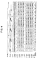
- a sample clock CK1 (C in Figure 4) at the frequency of 64.8 MHz (the period is represented by T) is supplied to the shift register 260 whereby the digital video signal is shifted.
- Four-bit outputs Q4 - Q1 of the shift register 260 are supplied, respectively, to four registers 201 - 204, each thereof being provided with an input enable terminal, and latched therein by a load pulse LD1 (E in Figure 4), having a frequency of 16.2 MHz and which goes low every 4-T period for the duration of 1 T, so as to cause output in parallel.
- the clock CK1 is also supplied to these registers 201 - 204.
- Each of the output data series D1A - D4A (F - I in Figure 4) of the registers 201 - 204 are supplied to registers 211, 212; 221, 222; 231, 232; and 241, 242, each thereof being provided with output enable terminals, and latched by a clock CK11 (J in Figure 4) at a frequency of 16.2 MHz.
- the registers 211, 221, 231 and 241 To the output enable terminals of the registers 211, 221, 231 and 241 is supplied the output of an inverter 263 which is an inverted form of the line identification pulse LNID (A in Figure 4) which is alternately brought high and low at intervals of one line, while the line identification pulse LNID is supplied as it is to the output enable terminals of the registers 212, 222, 232 and 242.
- the registers 211, 221, 231 and 241 and the registers 212, 222, 232 and 242 output their data alternately for each line period.
- a write enable pulse WE (0 in Figure 4) having a frequency of 16.2 MHz and a duty ratio of 50% is supplied to OR gates 261 and 262. Further, the line identification pulse LNID is supplied to the OR gate 261 and the output of the inverter 263 which inverts the line identification pulse LNID is supplied to the OR gate 262.
- the output of the OR gate 261 is supplied to the memories M11A, M21A, M31A and M41A as a write enable pulse, and the output of the OR gate 262 is supplied to the memories M12A, M22A, M32A and M42A as a write enable pulse.
- the memories M11A, M21A, M31A and M41A are brought into a write state, while the memories M12A, M22A, M32A and M42A are brought into a read state.
- the memories M11A, M21A, M31A, and M41A are brought into a read state, while the memories M12A, M22A, M32A and M42A are brought into a write state.
- the clock CK 11 is supplied to an address counter 264, and a write address therefrom is supplied to each of the memories M12A, M22A, M32A and M42A through a multiplexer 266 which is controlled for switching by the output of the inverter 263 i.e. the inverse of the line identification pulse.
- the write address from the address counter 264 is supplied to each of the memories M11A, M21A, M31A and M41A through a multiplexer 267 which is controlled for switching by the inverted line identification pulse supplied by the inverter 263.
- the write address from the address counter 264 is supplied to a ROM 265 to be subjected therein to an address conversion described below and the thus obtained read address is supplied through the multiplexer 266 to each of the memories M12A, M22A, M32A and M42A.
- the read address from the ROM 265 is supplied through the multiplexer 267 to each of the memories M11A, M21A, M31A and M41A.
- the write address of each memory is a regular address sequentially incremented as 0, 1, 2, 3 .. .. .
- the memory M11A is written in, for example, with the data of the first series (1) at the address 2 - 126, with the data of the second series (2) at the address 127-251, with the data of the third series (3) at the address 252 - 376, and with the data of the fourth series (4) at the address 377-501. From the temporal viewpoint, these data are of every fourth sample.
- the read address of each memory is obtained by address conversion in the ROM 265, and the same is arranged in the order of 0, 125, 250, 375, 1, 126, 251, 376 .. .. , with two reads occurring for each of the addresses for overlap portions at the front and the rear and one read each occuring of the address for the first series (1), second series (2), third series (3), and the fourth series (4) in between.
- the data samples which are located at the front and rear edges of picture areas are read out twice from the memories in order to protect the lacking or discrepancy of the data at those areas.
- the read addresses 0 to 376 shows the last two samples of the preceding data series, respectively. Thereafter, the data signals in each data series are conventionally read out from the memories in accordance with the read addresses 2,127,252,377.
- the registers 213, 223, 233 and 243 To the output enable terminals of the registers 213, 223, 233 and 243 is supplied the line identification pulse LNID (W in Figure 5) which is alternately brought high and low at intervals of one line and to the output enable terminal of the registers 214, 224, 234 and 244, is supplied the inverted pulse produced by the inverter 263 from the line identification pulse LNID. Therefore, the registers 211, 221, 231 and 241 and the registers 212, 222, 232 and 242 carry out output operations alternately for each line period.
- LNID line identification pulse
- Data series D13A (C in Figure 5) and D14A from the registers 213 and 214 are supplied to registers 215, 225, 235 and 245, each of which is provided with input and output enable terminals.
- Data series D23A (D in Figure 5) and D24A from the registers 223 and 224 are supplied to registers 216, 226, 236 and 246, each of which is provided with input and output enable terminals.
- Data series D33A (E in Figure 5) and D34A from the registers 233 and 234 are supplied to registers 217, 227, 237 and 247, each of which is provided with input and output enable terminals.
- Data series D43A (F in Figure 5) and D44A from the registers 243 and 244 are supplied to registers 218, 228, 238 and 248, each of which is provided with input and output enable terminals.
- P1 - P8 in Figure 5 indicate invalid data.
- These control signals G1A - G4A have a frequency of 4.05 MHz and are held at the low level for a 4-T period at intervals of a 16-T period, and their phases are shifted by 4T from one another.
- the output data series D13A, D23A, D33A and D43A from the registers 213, 223, 233 and 243 are latched, respectively, by the registers 215 - 218 when the control signal G1A is at the low level, by the registers 225 - 228 when the control signal G2A is at the low level, by the registers 235 - 238 when the control signal G3A is at the low level, and by the registers 245 - 248 when the control signal G4A is at the low level.
- the registers 215 - 218 only latch the data of the first series (1)
- the registers 225 - 228 only latch the data of the second series (2)
- the registers 235 - 238 only latch the data of the third series (3)
- the registers 245 - 248 only latch the data of the fourth series (4), each data thereof including overlap portions at the front and rear.
- the data series of the first series (1) latched by the registers 215 - 218 is sequentially supplied to a programmable shift register 251 in the order of the control signals G1A - G4A .
- the data series of the second series (2) latched by the registers 225 - 228 is sequentially supplied to a programmable shift register 252 in the order of the control signals G1A - G4A .
- the data series of the third series (3) latched by the registers 235 - 238 is sequentially supplied to a programmable shift register 253 in the order of the control signals G1A - G4A .
- the data series of the fourth series (4) latched by the registers 245 - 248 is sequentially supplied to a programmable shift register 254 in the order of the control signals G1A - G4A .
- Each of the data series R1A - R4A supplied to the programmable shift registers 251 - 254 are indicated by K - N in Figure 5, which are not in phase with one another.
- Relative values of shift amounts S1A, S2A, S3A and S4A of these programmable shift registers 251 - 254 are set to a 4-, 3-, 2- and 1-sample period, respectively.
- These programmable shift registers 251 - 254 are supplied with the clock CK11 as the shift pulse.
- output digital signals DATA#1 - DATA#4 (O - R and S - V in Figure 5), which are the digital video signals for four screens, namely the original screen divided into four sections in the horizontal direction and expanded to the size of the original screen and provided with overlap portions at both sides thereof.
- the four digital signals DATA#1 - DATA#4 are supplied to the data distributing circuit 11 of the signal processing portions 10 - 40, respectively.
Landscapes
- Engineering & Computer Science (AREA)
- Multimedia (AREA)
- Signal Processing (AREA)
- Color Television Systems (AREA)
- Television Systems (AREA)
- Television Signal Processing For Recording (AREA)
- Testing, Inspecting, Measuring Of Stereoscopic Televisions And Televisions (AREA)
- Compression Or Coding Systems Of Tv Signals (AREA)
Claims (6)
- Verfahren zur Umwandlung und Verarbeitung einer Vielzahl von digitalen Datensignalen, welche erste, zweite und dritte Videokomponenetensignale (Y, Cw, Cn) enthalten, gekennzeichnet durch folgende Verfahrensschritte:
räumliches Aufteilen jedes dieser digitalen Datensignale entsprechend N Ausschnitten eines dargestellten Bildes, wobei N eine ganze Zahl größer 2 ist;
Erweitern der aufgeteilten digitalen Datensignale, so daß diese eine N-fache Periode der Periode der Taktfrequenz der ursprünglichen digitalen Datensignale aufweisen, zur Erzeugung von aufgeteilten und erweiterten digitalen Datensignalen;
Verteilen (11) jedes der aufgeteilten und erweiterten digitalen Datensignale auf jeweils eine Gruppe von zwei Kanälen von Übertragungswegen, wobei die Daten des ersten Videokomponentensignals den zwei Kanälen der Übertragungswege wechselweise mit dazwischenliegenden Leerräumen zugeordnet werden;
Verwerfen der jeweils zweiten Daten der zweiten und dritten Videokomponentensignale und Übertragen der jeweils verbleibenden zweiten Daten dieser zweiten und dritten Videokomponentensignale wechselweise während jener Leerräume, die nicht durch das erste Videokomponentensignal belegt sind, auf jedem der Übertragungswege. - Verfahren nach Anspruch 1, bei dem das erste Videokomponentensignal ein Luminanz-Komponentensignal aufweist und bei dem die zweiten und dritten Videokomponentensignale Chrominanz-Komponentensignale aufweisen.
- Vorrichtung zur Umwandlung und Verarbeitung einer Vielzahl von digitalen Datensignalen, welche erste, zweite und dritte Videokomponenetensignale aufweisen, gekennzeichnet durch
Mittel (2) zum räumlichen Aufteilen jedes dieser digitalen Datensignale entsprechend N Ausschnitten eines dargestellten Bildes, wobei N eine ganze Zahl größer 2 ist;
Mittel (2) zum Erweitern jedes der aufgeteilten digitalen Datensignale zur Erreichung einer N-fachen Periode der Periode der Taktfrequenz der digitalen Datensignale;
Mittel (11) zum Verteilen jedes der aufgeteilten und erweiterten digitalen Datensignale von den Mitteln zur Erweiterung auf jeweils eine Gruppe von zwei Kanälen von Übertragungswegen;
Mittel (11) zur Verteilung, welche Mittel aufweisen um das erste Videokomponenetensignal in den zwei Kanälen der Übertragungswege wechselweise mit dazwischen liegenden Leerräumen anzuordnen;und
Mittel zum Verwerfen der jeweils zweiten Daten jedes der zweiten und dritten Videokomponentensignale und Mittel zum Übertragen der jeweils zweiten verbliebenen Daten der zweiten und dritten Videokomponenetensignale während der Leerräume, die nicht vom ersten Videokomponentensignal besetzt sind, wechselweise auf jedem der Übertragungswege. - Vorrichtung nach Anspruch 3, in der N zu 4 gewählt ist und die Taktfrequenzen jeder der aufgeteilten Videokomponentensignale auf ein Viertel reduziert sind, und in der die Videokomponentensignale entsprechend dem dargestellten Bild über vier Übertragungskreise übertragen werden.
- Vorrichtung nach Anspruch 3 oder 4, in der das erste Videokomponentensignal ein Luminanz-Komponentensignal aufweist und die zweiten und dritten Videokomponentensignale Chrominanzkomponentensignale aufweisen.
- Vorrichtung nach Anspruch 3 oder 4, in der die ersten, zweiten und dritten Videokomponentensignale jeweils grüne, rote und blaue Komponentensignale aufweisen.
Priority Applications (1)
| Application Number | Priority Date | Filing Date | Title |
|---|---|---|---|
| AT86308926T ATE78653T1 (de) | 1985-11-14 | 1986-11-14 | Verfahren und vorrichtung zur verwandlung und verarbeitung von fernsehsignalen. |
Applications Claiming Priority (2)
| Application Number | Priority Date | Filing Date | Title |
|---|---|---|---|
| JP60255454A JPH0746876B2 (ja) | 1985-11-14 | 1985-11-14 | テレビジョン信号伝送装置及びテレビジョン信号記録装置 |
| JP255454/85 | 1985-11-14 |
Publications (3)
| Publication Number | Publication Date |
|---|---|
| EP0224366A2 EP0224366A2 (de) | 1987-06-03 |
| EP0224366A3 EP0224366A3 (en) | 1988-08-03 |
| EP0224366B1 true EP0224366B1 (de) | 1992-07-22 |
Family
ID=17278991
Family Applications (1)
| Application Number | Title | Priority Date | Filing Date |
|---|---|---|---|
| EP86308926A Expired - Lifetime EP0224366B1 (de) | 1985-11-14 | 1986-11-14 | Verfahren und Vorrichtung zur Verwandlung und Verarbeitung von Fernsehsignalen |
Country Status (8)
| Country | Link |
|---|---|
| EP (1) | EP0224366B1 (de) |
| JP (1) | JPH0746876B2 (de) |
| KR (1) | KR950008684B1 (de) |
| AT (1) | ATE78653T1 (de) |
| AU (1) | AU596815B2 (de) |
| CA (1) | CA1300734C (de) |
| DE (1) | DE3686134T2 (de) |
| HK (1) | HK86395A (de) |
Families Citing this family (4)
| Publication number | Priority date | Publication date | Assignee | Title |
|---|---|---|---|---|
| JPH01160289A (ja) * | 1987-12-17 | 1989-06-23 | Sony Corp | ディジタル映像信号の伝送方式 |
| US5111303A (en) * | 1989-02-27 | 1992-05-05 | Pioneer Electronic Corporation | Video signal recording system and picture display system in a high-definition television system |
| JP2738008B2 (ja) * | 1989-04-28 | 1998-04-08 | ソニー株式会社 | ディジタル映像信号の伝送方式 |
| JPH06153151A (ja) * | 1992-10-31 | 1994-05-31 | Sony Corp | ディジタルビデオ信号記録装置 |
Family Cites Families (7)
| Publication number | Priority date | Publication date | Assignee | Title |
|---|---|---|---|---|
| US3986202A (en) * | 1975-03-05 | 1976-10-12 | Eastman Kodak Company | Processing apparatus and method for color video signals |
| GB2068673B (en) * | 1980-01-30 | 1983-09-07 | Sony Corp | Decoding and recoding composite digital colour television signals |
| JPS57125588A (en) * | 1981-01-29 | 1982-08-04 | Sony Corp | Digital reproducing device for video signal |
| DE3121847C2 (de) * | 1981-06-02 | 1987-04-16 | Robert Bosch Gmbh, 7000 Stuttgart | Verfahren zur Übertragung und/oder Speicherung digital codierter Farbfernsehsignale |
| CA1223333A (en) * | 1983-07-29 | 1987-06-23 | Yoshiyuki Ota | Video signal processing apparatus |
| JPS6022886A (ja) * | 1984-06-13 | 1985-02-05 | Hitachi Ltd | デイジタル画像信号の記録再生装置 |
| JPH0722411B2 (ja) * | 1985-05-13 | 1995-03-08 | 株式会社日立製作所 | デイジタル記録再生装置 |
-
1985
- 1985-11-14 JP JP60255454A patent/JPH0746876B2/ja not_active Expired - Lifetime
-
1986
- 1986-10-31 CA CA000521910A patent/CA1300734C/en not_active Expired - Lifetime
- 1986-11-03 AU AU64823/86A patent/AU596815B2/en not_active Expired
- 1986-11-12 KR KR1019860009529A patent/KR950008684B1/ko not_active Expired - Lifetime
- 1986-11-14 DE DE8686308926T patent/DE3686134T2/de not_active Expired - Lifetime
- 1986-11-14 AT AT86308926T patent/ATE78653T1/de not_active IP Right Cessation
- 1986-11-14 EP EP86308926A patent/EP0224366B1/de not_active Expired - Lifetime
-
1995
- 1995-06-01 HK HK86395A patent/HK86395A/en not_active IP Right Cessation
Also Published As
| Publication number | Publication date |
|---|---|
| KR870005535A (ko) | 1987-06-09 |
| EP0224366A3 (en) | 1988-08-03 |
| JPS62115981A (ja) | 1987-05-27 |
| AU596815B2 (en) | 1990-05-17 |
| EP0224366A2 (de) | 1987-06-03 |
| DE3686134T2 (de) | 1992-12-17 |
| AU6482386A (en) | 1987-05-21 |
| JPH0746876B2 (ja) | 1995-05-17 |
| KR950008684B1 (ko) | 1995-08-04 |
| ATE78653T1 (de) | 1992-08-15 |
| DE3686134D1 (de) | 1992-08-27 |
| CA1300734C (en) | 1992-05-12 |
| HK86395A (en) | 1995-06-09 |
Similar Documents
| Publication | Publication Date | Title |
|---|---|---|
| US4661862A (en) | Differential PCM video transmission system employing horizontally offset five pixel groups and delta signals having plural non-linear encoding functions | |
| EP0234483A2 (de) | Videosignalaufzeichnungsmethode und Vorrichtung zur Teilbildaufnahme | |
| EP0321217B1 (de) | System zur Übertragung eines Digitalvideosignales | |
| EP0575997B1 (de) | Vorrichtung zum Verarbeiten des Signals eines digitalen Videocassettenrecorders | |
| US4737863A (en) | Method for distributing and recording video signals and an apparatus using the same | |
| EP0224366B1 (de) | Verfahren und Vorrichtung zur Verwandlung und Verarbeitung von Fernsehsignalen | |
| JPH06153151A (ja) | ディジタルビデオ信号記録装置 | |
| US6865228B2 (en) | Digital data transmission apparatus and method for multiplexing multiplexing multi-channel video data within active video periods | |
| US5295024A (en) | Method and apparatus for two-channel recording of video signals | |
| EP0920205B1 (de) | Digitaldatenübertragungsvorrichtung und -verfahren | |
| EP0624989B1 (de) | Gerät zur Aufzeichnung und Wiedergabe von digitalen Videosignalen | |
| JPH05130593A (ja) | 符号化装置 | |
| JP2004120799A (ja) | ディジタルデータ伝送装置及びその伝送方法 | |
| US5264920A (en) | Word rate conversion processing device for processor circuit for processing digital component video signals sampled by different sampling frequencies | |
| JPH01114277A (ja) | ブロック化回路 | |
| JPH0832928A (ja) | Hd信号記録装置 | |
| JPH09238309A (ja) | 画像伝送装置 | |
| JP3536392B2 (ja) | 順次走査信号記録装置 | |
| JP2837771B2 (ja) | 符号化および復号化装置 | |
| JPS6025389A (ja) | 撮像装置 | |
| JP3136599B2 (ja) | 映像信号記録装置及び映像信号再生装置 | |
| JPH01165281A (ja) | 伝送方法及び伝送装置 | |
| JPH05266597A (ja) | ディジタル磁気記録装置とディジタル磁気再生装置 | |
| JPH05328404A (ja) | 映像信号の高能率符号化装置 | |
| JPS62176286A (ja) | ビデオ信号伝送システム |
Legal Events
| Date | Code | Title | Description |
|---|---|---|---|
| PUAI | Public reference made under article 153(3) epc to a published international application that has entered the european phase |
Free format text: ORIGINAL CODE: 0009012 |
|
| 17P | Request for examination filed |
Effective date: 19861125 |
|
| AK | Designated contracting states |
Kind code of ref document: A2 Designated state(s): AT DE FR GB NL |
|
| PUAL | Search report despatched |
Free format text: ORIGINAL CODE: 0009013 |
|
| AK | Designated contracting states |
Kind code of ref document: A3 Designated state(s): AT DE FR GB NL |
|
| 17Q | First examination report despatched |
Effective date: 19901102 |
|
| GRAA | (expected) grant |
Free format text: ORIGINAL CODE: 0009210 |
|
| AK | Designated contracting states |
Kind code of ref document: B1 Designated state(s): AT DE FR GB NL |
|
| REF | Corresponds to: |
Ref document number: 78653 Country of ref document: AT Date of ref document: 19920815 Kind code of ref document: T |
|
| REF | Corresponds to: |
Ref document number: 3686134 Country of ref document: DE Date of ref document: 19920827 |
|
| ET | Fr: translation filed | ||
| PLBE | No opposition filed within time limit |
Free format text: ORIGINAL CODE: 0009261 |
|
| STAA | Information on the status of an ep patent application or granted ep patent |
Free format text: STATUS: NO OPPOSITION FILED WITHIN TIME LIMIT |
|
| 26N | No opposition filed | ||
| REG | Reference to a national code |
Ref country code: GB Ref legal event code: IF02 |
|
| PGFP | Annual fee paid to national office [announced via postgrant information from national office to epo] |
Ref country code: NL Payment date: 20051106 Year of fee payment: 20 |
|
| PGFP | Annual fee paid to national office [announced via postgrant information from national office to epo] |
Ref country code: FR Payment date: 20051108 Year of fee payment: 20 |
|
| PGFP | Annual fee paid to national office [announced via postgrant information from national office to epo] |
Ref country code: GB Payment date: 20051109 Year of fee payment: 20 |
|
| PGFP | Annual fee paid to national office [announced via postgrant information from national office to epo] |
Ref country code: DE Payment date: 20051110 Year of fee payment: 20 |
|
| PGFP | Annual fee paid to national office [announced via postgrant information from national office to epo] |
Ref country code: AT Payment date: 20051111 Year of fee payment: 20 |
|
| PG25 | Lapsed in a contracting state [announced via postgrant information from national office to epo] |
Ref country code: GB Free format text: LAPSE BECAUSE OF EXPIRATION OF PROTECTION Effective date: 20061113 |
|
| PG25 | Lapsed in a contracting state [announced via postgrant information from national office to epo] |
Ref country code: NL Free format text: LAPSE BECAUSE OF EXPIRATION OF PROTECTION Effective date: 20061114 |
|
| REG | Reference to a national code |
Ref country code: GB Ref legal event code: PE20 |
|
| NLV7 | Nl: ceased due to reaching the maximum lifetime of a patent |
Effective date: 20061114 |