EP0223232A2 - Druckluft-Kompressor - Google Patents
Druckluft-Kompressor Download PDFInfo
- Publication number
- EP0223232A2 EP0223232A2 EP86115983A EP86115983A EP0223232A2 EP 0223232 A2 EP0223232 A2 EP 0223232A2 EP 86115983 A EP86115983 A EP 86115983A EP 86115983 A EP86115983 A EP 86115983A EP 0223232 A2 EP0223232 A2 EP 0223232A2
- Authority
- EP
- European Patent Office
- Prior art keywords
- compressed air
- container
- pressure
- opening
- air compressor
- Prior art date
- Legal status (The legal status is an assumption and is not a legal conclusion. Google has not performed a legal analysis and makes no representation as to the accuracy of the status listed.)
- Granted
Links
Images
Classifications
-
- B—PERFORMING OPERATIONS; TRANSPORTING
- B05—SPRAYING OR ATOMISING IN GENERAL; APPLYING FLUENT MATERIALS TO SURFACES, IN GENERAL
- B05B—SPRAYING APPARATUS; ATOMISING APPARATUS; NOZZLES
- B05B9/00—Spraying apparatus for discharge of liquids or other fluent material, without essentially mixing with gas or vapour
- B05B9/007—At least a part of the apparatus, e.g. a container, being provided with means, e.g. wheels, for allowing its displacement relative to the ground
-
- B—PERFORMING OPERATIONS; TRANSPORTING
- B05—SPRAYING OR ATOMISING IN GENERAL; APPLYING FLUENT MATERIALS TO SURFACES, IN GENERAL
- B05B—SPRAYING APPARATUS; ATOMISING APPARATUS; NOZZLES
- B05B9/00—Spraying apparatus for discharge of liquids or other fluent material, without essentially mixing with gas or vapour
- B05B9/03—Spraying apparatus for discharge of liquids or other fluent material, without essentially mixing with gas or vapour characterised by means for supplying liquid or other fluent material
- B05B9/04—Spraying apparatus for discharge of liquids or other fluent material, without essentially mixing with gas or vapour characterised by means for supplying liquid or other fluent material with pressurised or compressible container; with pump
-
- F—MECHANICAL ENGINEERING; LIGHTING; HEATING; WEAPONS; BLASTING
- F04—POSITIVE - DISPLACEMENT MACHINES FOR LIQUIDS; PUMPS FOR LIQUIDS OR ELASTIC FLUIDS
- F04B—POSITIVE-DISPLACEMENT MACHINES FOR LIQUIDS; PUMPS
- F04B35/00—Piston pumps specially adapted for elastic fluids and characterised by the driving means to their working members, or by combination with, or adaptation to, specific driving engines or motors, not otherwise provided for
- F04B35/06—Mobile combinations
-
- F—MECHANICAL ENGINEERING; LIGHTING; HEATING; WEAPONS; BLASTING
- F04—POSITIVE - DISPLACEMENT MACHINES FOR LIQUIDS; PUMPS FOR LIQUIDS OR ELASTIC FLUIDS
- F04B—POSITIVE-DISPLACEMENT MACHINES FOR LIQUIDS; PUMPS
- F04B39/00—Component parts, details, or accessories, of pumps or pumping systems specially adapted for elastic fluids, not otherwise provided for in, or of interest apart from, groups F04B25/00 - F04B37/00
Definitions
- the invention relates to a compressed air compressor having a drive motor and a compressor connected to it and having a pressure container having a compressed air inlet opening and an outlet opening.
- the invention has for its object to design a compressed air compressor of the type mentioned so that it can be used more universally and can not only serve as a compressed air source for various separate tools operated by compressed air.
- the compressed air compressor mentioned at the outset in that it can be used either as a spray or spray device for liquids or powdery substances and its pressure container can be used as a material container with compressed air cushion in conjunction with a suitable application device for the spray material and for this purpose its top in addition to its compressed air inlet port with a relative large, tightly and pressure-tightly closable opening by means of a lid is provided for the spray material and for cleaning.
- the compressed air compressor designed according to the invention can thus either as a pure compressed air source, the compressed air line connected to the pressure container can be connected to any compressed air operated tools, or as a spraying or spraying unit, in which the pressure container itself as a storage container for a liquid to be sprayed or a powder to be sprayed is used.
- a compressed air compressor according to the invention thus saves a separate spray device.
- the pressure vessel which can have a circular cylindrical cross section in a manner known per se, is arranged with a vertical axis and is provided with an upper opening which captures its full cross section and which can be placed tightly against an annular flange on the container opening and lockable lid is closable.
- the unit part comprising the drive motor and the compressed air pump can expediently be arranged next to the pressure container on a common movable support, which facilitates handling on the pressure container when switching from pure compressed air operation to spray operation.
- the compressed air inlet opening can advantageously be arranged in the container wall near the opening edge, while a liquid outlet opening is provided at the lowest point of the pressure container bottom and in the removable one Cover a pressure relief valve, a vent valve, a pressure indicator and a pressure reducer with quick coupling for removing compressed air are arranged in a known manner.
- the compressed air compressor according to the invention can spray both thin and viscous media as a liquid spray device.
- a receptacle-shaped inner container which can be inserted through the filling opening and into which a piece of pipe or hose protrudes as a riser pipe, which leads to an additional spray material outlet opening formed in the cover, can expediently be arranged in the interior of the pressure container to accommodate low-viscosity spray media.
- the inner container has the advantage that the spraying material can only contaminate it and the riser, but not the pressure container.
- the compressed air compressor of this type can be manufactured in various sizes, both in a manner that can be easily moved by one person, as used by any homeowner for the home (e.g. application of emulsion paints etc.), garden (e.g. Root fertilization of trees and bushes by liquid fertilizers or spraying of plant protection products) and for vehicle maintenance (warm water and cleaning agents are used under pressure via a cleaning gun for cleaning cars etc., as well of course in connection with a washing brush etc.) in larger, expediently also mobile versions, but also in the stationary area for areas of application in the field of agriculture (liming, disinfecting) in the area of building cleaning, painting companies, truck companies (cleaning tarpaulins and vehicles, for sandblasting, for the application of alto oil, for the application of cold cleaners etc.) and for many other areas where liquid or powdery media can be transported using compressed air.
- emulsion paints etc. e.g. Root fertilization of trees and bushes by liquid fertilizers or spraying of plant protection products
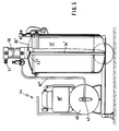
- the assembly shown in the drawing has a tubular frame 10 which forms a horizontal mounting plane, has a stand 11 at one end and is provided with an axle 12 for two wheels 13 in the area of another end.
- a pressure vessel 14 with a circular cylindrical cross section and vertical axis 15 is arranged above the axis 12 and its bottom part 16 is fixedly connected to the tubular frame 10, for example by means of weld seams 17 (FIG. 1).
- the aggregate part 18, which has a drive motor and a compressor, is arranged and, for example, likewise firmly connected to the tubular frame 10 by means of weld seams 17.
- the individual parts of the unit part 18 are not described in detail because they are insignificant for the invention.
- a compressed air line 19 leads via a small expansion tank 20 with a condensate separator 20 to a compressed air inlet opening 21 which is formed in the upper part of the compressed air tank 14 near its upper opening edge 22.
- the upper opening 23 with the opening edge 22 of the pressure container comprises the full cross section of the pressure container 14.
- the pressure container is provided with an outer ring flange 24, into which a sealing ring 25 is inserted, against which the edge of the container opening 23 closes, releasable cover 26 comes to rest.
- the cover 26 of the container is held tightly and pressure-tightly against the flange ring 24 of the pressure container 14 by means of clamping screws 27, which are held in clamping claws 28 which are pivotably mounted between bearing wings 29 welded onto the outside of the pressure container 14.
- a total of five pivotable clamping claws 28 are provided in the exemplary embodiment shown, one of which is shown in FIG. 1, while FIG. 3 also shows the bearing wings 29 of the other clamping claws.
- a combined safety and ventilation valve 30 and a pressure indicator 31 are arranged in the cover 26.
- the lid is provided with a spray agent outlet opening 32 in addition to a first spray agent outlet opening 33 formed at the lowest point of the container bottom part 16.
- Appropriate application devices, not shown here, for the spray material can be connected to the outlet openings 32, 33 via hose or pipelines.
- a riser pipe 34, indicated by dash-dotted lines in FIG. 1, can be connected to the spray-medium outlet opening 32 of the lid 26, which as far as the bottom of a cup-like or bucket-like container 35, which can be inserted into the container opening 23 and is also indicated by dash-dotted lines in FIG. 1 leads, which is provided in particular for receiving low-viscosity spray media and can be used optionally in the pressure vessel 14.
- a pressure reducer (not shown) with a quick coupling for removing compressed air is also provided in the cover.
- two handle brackets 36 are fastened, to which the support 10 can be tilted for moving the unit.
- Fig. 4 shows an embodiment of the unit, which differs from the embodiment according to FIGS. 1 to 3 in that a compressed air reservoir 40 is interposed between the unit part 18 'having the drive motor and a compressor and the pressure vessel 14.
- the compressed air storage container 40 is connected via a pressure line 19 'to the compressed air inlet opening 21 of the compressed air container 14 via a pressure reducing valve 42 which is infinitely adjustable on a rotary knob 41 and which is combined with a water separator 43.
- the unit part 18 'and the compressed air reservoir 40 are combined to form a compressor part 44 which has a common support 45 which is detachably connected to the tubular frame 10 of the unit via connecting screws with wing nuts 46. After loosening the wing nuts 46 and loosening the pressure line 19 ', the compressor part 24 can be removed from the tubular frame 10 at a coupling point 47 and used separately as a compressor unit.
- the compressed air reservoir 40 has the advantage that the pressure in it can vary according to the switch-on and switch-off pressure of the compressor unit part 18 ', while the pressure in the pressure container 14, which serves as a material container, is infinitely variable by means of the pressure reducing valve 42 certain value can be set. This allows the use of the unit to be extended to additional areas.
- the water separator 43 ensures that no condensed water from the compressed air storage container 40 gets into the pressure container 14.
- the unit is provided with a complete compressor part 44 with the compressed air reservoir 40.
- a pump 50 is detachably mounted on the cover 26 'of the pressure container 14' via a centrally or decentrally arranged outlet opening 33 ', which, with the air pressure adjustable on the pressure reducing valve 42, for pumping material from the pressure container 14' is driven.
- a compressed air line 19 ′′ leads from the pressure reducing valve 42 of the compressed air storage container 40 to the pump 50 attached.
- the pressure container 14 ′ is not used as an overpressure container.
- the pump 50 can be designed as a booster pump, in which the pressure supplied by the pressure reducing valve 42 of, for example, 8 bar is used in a transmission ratio of, for example, 1:50, 1:15 or 1:10 to a higher outlet pressure.
- a grease gun as an additional device, an Airleß spray gun or a high-pressure washing gun can be connected to the pressure outlet 51 of the pump 50, which dispense the lubricating material, coloring material or cleaning material accommodated in the container 14, which projects over the bottom of the pressure container 14 ' Riser pipe 34 'is pulled up by the pump 50.
- the material to be discharged by means of the pump can also be accommodated in the pressure container 14 'in a separate inner container, as is indicated in FIG. 1.
- the pump 50 permits an additional expansion of the area of use of the versatile unit, the pump also being designed as an electric pump and therefore without changing the Connection lines to the compressor part 44 on the storage container 14 of the embodiment of FIG. 4 could optionally be placed.
Landscapes
- Engineering & Computer Science (AREA)
- Mechanical Engineering (AREA)
- General Engineering & Computer Science (AREA)
- Nozzles (AREA)
- Compressors, Vaccum Pumps And Other Relevant Systems (AREA)
- Compressor (AREA)
Abstract
Description
- Die Erfindung betrifft einen Druckluft-Kompressor mit einem Antriebsmotor und einem mit ihm verbundenen Verdichter und mit einem eine Druckluft-Einlaßöffnung und eine Auslaßöffnung aufweisenden Druckbehälter.
- Der Erfindung liegt die Aufgabe zugrunde, einen Druckluft-Kompressor der genannten Art so auszubilden, daß er universeller einsetzbar wird und nicht nur als Druckluftquelle für verschiedene gesonderte druckluftbetriebene Werkzeuge dienen kann.
- Die gestellte Aufgabe wird mit dem eingangs genannten Druckluft-Kompressor erfindungsgemäß dadurch gelöst, daß er wahlweise als Sprüh- oder Spritzvorrichtung für Flüssigkeiten oder pulverförmige Stoffe verwendbar ist und sein Druckbehälter als Materialbehälter mit Druckluftpolster in Verbindung mit einer passenden Auftragvorrichtung für das Spritzmaterial einsetzbar und hierzu auf seiner Oberseite zusätzlich zu seiner Druckluft-Einlaßöffnung mit einer relativ großen, mittels eines Deckels dicht und druckfest verschließbaren Öffnung zum Befallen mit dem Spritzmaterial und zum Reinigen versehen ist.
- Der erfindungsgemäß ausgebildete Druckluft-Kompressor kann also wahlweise als reine Druckluftquelle, dessen an den Druckbehälter angeschlossene Druckluftleitung mit beliebigen druckluftbetriebenen Werkzeugen verbunden werden kann, oder aber als Sprüh- oder Spritzaggregat, bei welchem-der Druckbehälter selbst als Speicherbehälter für eine zu verspritzende Flüssigkeit oder ein zu versprühendes Pulver dient, verwendet werden. Ein Druckluft-Kompressor gemäß der Erfindung erspart somit eine gesonderte Spritzvorrichtung.
- Bei einer bevorzugten Ausführungsform des Druckluft-Kompressors ist der Druckbehälter, der in an sich bekannter Weise einen kreiszylindrischen Querschnitt aufweisen kann, mit vertikaler Achse angeordnet und mit einer seinen vollen Querschnitt erfassenden oberen Öffnung versehen, die durch einen gegen einen Ringflansch an der Behälteröffnung dicht aufsetzbaren und festspannbaren Deckels verschließbar ist. Der den Antriebsmotor und die Druckluftpumpe aufweisende Aggregatteil kann zweckmäßig neben dem Druckbehälter auf einem gemeinsamen verfahrbaren Träger angeordnet sein, was die Handhabung am Druckbehälter bei der Umstellung von reinem Druckluftbetrieb auf Spritzbetrieb erleichtert. An dem mit vertikaler Achse angeordneten Druckbehälter kann die Druckluft-Einlaßöffnung vorteilhafterweise in der Behälterwandung nahe des Öffnungsrandes angeordnet sein, während an der tiefsten Stelle des Druckbehälterbodens eine Flüssigkeits-Austrittsöffnung vorgesehen ist und im abnehmbaren Deckel in bekannter Weise ein Überdruckventil, ein Entlüftungsventil, ein Druckanzeiger und ein Druckminderer mit Schnellkupplung zur Entnahme von Druckluft angeordnet sind.
- Der Druckluft-Kompressor gemäß der Erfindung kann als Flüssigkeits-Spritzvorrichtung sowohl dünnflüssige als auch dickflüssige Medien versprühen. Zur Aufnahme dünnflüssiger Spritzmedien kann zweckmäßig im Innern des Druckbehälters ein durch die Befüllöffnung einsetzbarer napfförmiger Innenbehälter angeordnet sein, in welchen ein Rohr- oder Schlauchstück als Steigleitung hineinragt, das zu einer im Deckel ausgebildeten zusätzlichen Spritzmaterial-Austrittsöffnung führt. Der Innenbehälter ergibt den Vorteil, daß das Spritzmateriäl nur ihn und die Steigleitung, nicht aber den Druckbehälter-verschmutzen kann.
- Der Druckluft-Kompressor dieser Art läßt sich in verschiedenen Größen herstellen, sowohl in einer von einer Person leicht verfahrbaren Art, wie sie von jedem Hausbesitzer für die Bereiche Haus (z. B. Auftragen von Dispersionsfarben etc.), Garten (z. B. Wurzeldüngung von Bäumen und Sträuchern durch flüssige Düngemittel bzw. Verspritzen von Pflanzenschutzmittel) und zur Fahrzeugpflege (warmes Wasser und Reinigungsmittel werden unter Druck über eine Reinigungspistole zur Reinigung von Autos etc. eingesetzt, ebenso natürlich in Verbindung mit Waschbürste etc.) benötigt werden, als auch in größeren, zweckmäßigerweise ebenfalls fahrbaren Ausführungsformen, aber auch im stationären Bereich für Einsatzgebiete im Bereich der Landwirtschaft (Kalken, Desinfizieren) im Bereich Gebäudereinigung, bei Malerbetrieben, bei LKW-Betrieben (Planen- und Fahrzeugreinigung, zum Sandstrahlen, zum Auftragen von Altoel, zum Auftragen von Kaltreiniger etc.) und für viele andere Bereiche, wo eben flüssige oder pulverförmige Medien mittels Druckluft transportiert werden können.
- Nachfolgend wird ein Ausführungsbeispiel eines erfindungsgemäß ausgebildeten Druckluft-Kompressors anhand der beiliegenden Zeichnung näher erläutert.
- Im einzelnen zeigen:
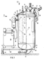
- Fig. 1 eine Seitenansicht des auf einem fahrbaren Träger angeordneten Aggregats mit einem vertikalen Längsschnitt durch die eine Hälfte des Druckbehälters;
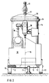
- Fig. 2 eine Vorderansicht des Aggregats in Richtung des Pfeiles II in Fig. l;
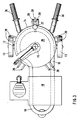
- Fig. 3 eine schematische Draufsicht auf das Aggregat in Richtung des Pfeiles III in Fig. 1;
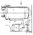
- Fig. 4 eine Seitenansicht einer anderen Ausführungsform des Aggregates mit einem Druckluft-Vorratsbehälter;
- Fig. 5 eine Seitenansicht eines dritten Ausführungsbeispiels des Aggregates mit einer auf den Druckbehälter aufgesetzten Pumpe.
- Das in der Zeichnung dargestellte Aggregat weist einen Rohrrahmen 10 auf, der eine horizontale Montageebene bildet, an seinem einen Ende einen Standfuß 11 aufweist und im Bereich eines anderen Endes mit einer Achse 12 für zwei Räder 13 versehen ist. Oberhalb der Achse 12 ist ein Druckbehälter 14 mit kreiszylindrischem Querschnitt und vertikaler Achse 15 angeordnet und mit seinem Bodenteil 16 beispielsweise mittels Schweißnähten 17 (Fig. 1) mit dem Rohrrahmen 10 fest verbunden. Nebem dem Druckbehälter 14 ist der einen Antriebsmotor und einen Verdichter aufweisende Aggregatteil 18 angeordnet und beispielsweise ebenfalls mittels Schweißnähten 17 fest mit dem Rohrrahmen 10 verbunden. Die Einzelteile des Aggregatteiles 18 sind nicht näher bezeichnet, weil sie für die Erfindung unwesentlich sind. Vom Aggregatteil 18 führt eine Druckluftleitung 19 über einen kleinen Ausgleichsbehälter 20 mit Kondenswasserabscheider 20 zu einer Drucklufteinlaßöffnung 21, die im oberen Teil des Druckluftbehälters 14 nahe seines oberen öffnungsrandes 22 ausgebildet ist.
- Die obere öffnung 23 mit dem Öffnungsrand 22 des Druckbehälters umfaßt den vollen Querschnitt des Druckbehälters 14. An seinem öffnungsrand 22 ist der Druckbehälter mit einem äußeren Ringflansch 24 versehen, in welchen ein Dichtungsring 25 eingesetzt ist, gegen welchen der Rand des die Behälteröffnung 23 verschließenden, lösbaren Deckels 26 zur Anlage kommt. Der Deckel 26 des Behälters wird mittels Spannschrauben 27 dicht und druckfest gegen den Flanschring 24 des Druckbehälters 14 gehalten, die in Spannpratzen 28 gehaltert sind, die zwischen auf der Außenseite des Druckbehälters 14 angeschweißten Lagerflügeln 29 verschwenkbar gelagert sind. Insgesamt sind beim dargestellten Ausführungsbeispiel fünf verschwenkbare Spannpratzen 28 vorgesehen, von denen eine in Fig. 1 dargestellt ist, während Fig. 3 die Lagerflügel 29 auch der anderen Spannpratzen zeigt.
- Im Deckel 26 sind ein kombiniertes Sicherheits- und Entlüftungsventil 30 und ein Druckanzeiger 31 angeordnet. Außerdem ist der Deckel mit einer Spritzmittel-Austrittsöffnung 32 zusätzlich zu einer an der tiefsten Stelle des Behälterbodenteiles 16 ausgebildeten ersten Spritzmittel-Austrittsöffnung 33 versehen. An die Austrittsöffnungen 32, 33 können über Schlauch- oder Rohrleitungen passende, hier nicht dargestellte Auftragvorrichtungen für das Spritzmaterial angeschlossen werden. An die Spritzmittel-Austrittsöffnung 32 des Deckels 26 kann ein in Fig. 1 mit strichpunktierten Linien angedeutetes Steigrohr 34 angeschlossen werden, das bis zum Boden eines in die Behälteröffnung 23 einsetzbaren, in Fig. 1 ebenfalls mit strichpunktierten Linien angedeuteten napf- oder eimerartigen Behälters 35 führt, der insbesondere für die Aufnahme dünnflüssiger Spritzmedien vorgesehen ist und wahlweise in den Druckbehälter 14 einsetzbar ist. Im Deckel ist auch ein nicht dargestellter Druckminderer mit Schnellkupplung zur Entnahme von Druckluft vorgesehen.
- Am Rohrrahmen 10 oder - wie beim dargestellten Ausführungsbeispiel - am fest mit dem Rohrrahmen 10 verbundenen Druckbehälter 14 sind zwei Griffbügel 36 befestigt, an welchen der Träger 10 zum Verfahren des Aggregats gekippt werden kann.
- Fig. 4 zeigt eine Ausführungsform des Aggregats, das sich gegenüber der Ausführungsform nach den Fig. 1 bis 3 dadurch unterscheidet, daß zwischen den den Antriebsmotor und einen Verdichter aufweisenden Aggregatteil 18' und den Druckbehälter 14 ein Druckluft-Vorratsbehälter 40 zwischengeschaltet ist. Der Druckluft-Vorratsbehälter 40 ist über ein-an einem Drehknopf 41 stufenlos einstellbares Druckminderventil 42, das mit einem Wasserabscheider 43 kombiniert ist, über eine Druckleitung 19' mit der Drucklufteinlaßöffnung 21 des Druckluftbehälters 14 verbunden. Das Aggregatteil 18' und der Druckluft-Vorratsbehälter 40 sind zu einem Kompressorteil 44 kombiniert, das einen gemeinsamen Träger 45 aufweist, der mit dem Rohrrahmen 10 des Aggregats über Verbindungsschrauben mit Flügelmuttern 46 lösbar verbunden ist. Das Kompressorteil 24 kann nach Lösen der Flügelmuttern 46 und nach Lösen der Druckleitung 19' an einer Kopplungsstelle 47 vom Rohrrahmen 10 abgenommen und gesondert als Kompressoraggregat eingesetzt werden.
- Der Druckluft-Vorratsbehälter 40 bringt den Vorteil, daß in ihm entsprechend dem Ein- und Ausschaltdruck des Verdichter-Aggregatteiles 18' der Druck unterschiedlich hoch sein kann, während der Druck im Druckbehälter 14, der als Materialbehälter dient, mittels des Druckminderventiles 42 stufenlos auf einen bestimmten Wert eingestellt werden kann. Dadurch läßt sich der Einsatz des Aggregates auf zusätzliche Gebiete erweitern. Durch den Wasserabscheider 43 wird sichergestellt, daß kein Kondenswasser aus dem Druckluft-Vorratsbehälter 40 in den Druckbehälter 14 gelangt.
- Auch bei der Ausführungsform nach Fig. 5 ist das Aggregat mit einem kompletten Kompressorteil 44 mit dem Druckluft-Vorratsbehälter 40 versehen. Im Gegensatz zu den beiden vorher beschriebenen Ausführungsbeispielen ist auf dem Deckel 26' des Druckbehälters 14' über einer zentral oder dezentral angeordneten Austrittsöffnung 33' eine Pumpe 50 lösbar montiert, die mit dem am Druckminderventil 42 einstellbaren Luftdruck zum Pumpen von Material aus dem Druckbehälter 14' angetrieben wird. Zu diesem Zweck führt eine Druckluftleitung 19'' vom Druckminderventil 42 des Druckluft-Vorratsbehälters 40 zur aufgesetzten Pumpe 50. In diesem Fall wird der Druckbehälter 14' nicht als überdruckbehälter eingesetzt. Die Pumpe 50 kann als Ubersetzerpumpe ausgebildet sein, in welcher der vom Druckminderventil 42 gelieferte Druck von beispielsweise 8 bar in einem übersetzungsverhältnis von beispielsweise 1:50, 1:15 oder 1:10 zu einem höheren Ausgangsdruck verwertet wird. So können am Druckausgang 51 der Pumpe 50 beispielsweise eine Fettpresse als Zusatzgerät, eine Airleß-Spritzpistole oder eine Hochdruck-Waschpistole angeschlossen werden, die das im Behälter 14 untergebrachte Schmiermaterial, Farbmaterial oder Reinigungsmaterial ausbringen, das über ein bis zum Boden des Druckbehälters 14' ragendes Steigrohr 34' von der Pumpe 50 hochgezogen wird.
- Das mittels der Pumpe auszutragende Material kann im Druckbehälter 14' auch in einem gesonderten Innenbehälter, wie er in Fig. 1 angedeutet ist, untergebracht sein. Die Pumpe 50 erlaubt eine zusätzliche Erweiterung des Einsatzgebietes des vielseitigen Aggregates, wobei die Pumpe auch als Elektropumpe ausgebildet sein und dadurch ohne eine Änderung der Verbindungsleitungen zum Kompressorteil 44 auf den Vorratsbehälter 14 der Ausführungsform nach Fig. 4 wahlweise aufgesetzt werden könnte.
Claims (10)
Priority Applications (1)
| Application Number | Priority Date | Filing Date | Title |
|---|---|---|---|
| AT86115983T ATE76789T1 (de) | 1985-11-21 | 1986-11-18 | Druckluft-kompressor. |
Applications Claiming Priority (2)
| Application Number | Priority Date | Filing Date | Title |
|---|---|---|---|
| DE3541170 | 1985-11-21 | ||
| DE19853541170 DE3541170A1 (de) | 1985-11-21 | 1985-11-21 | Druckluft-kompressor |
Publications (3)
| Publication Number | Publication Date |
|---|---|
| EP0223232A2 true EP0223232A2 (de) | 1987-05-27 |
| EP0223232A3 EP0223232A3 (en) | 1989-03-15 |
| EP0223232B1 EP0223232B1 (de) | 1992-06-03 |
Family
ID=6286474
Family Applications (1)
| Application Number | Title | Priority Date | Filing Date |
|---|---|---|---|
| EP86115983A Expired - Lifetime EP0223232B1 (de) | 1985-11-21 | 1986-11-18 | Druckluft-Kompressor |
Country Status (3)
| Country | Link |
|---|---|
| EP (1) | EP0223232B1 (de) |
| AT (1) | ATE76789T1 (de) |
| DE (1) | DE3541170A1 (de) |
Cited By (2)
| Publication number | Priority date | Publication date | Assignee | Title |
|---|---|---|---|---|
| FR2742362A1 (fr) * | 1995-12-13 | 1997-06-20 | Bouhet Bruno | Appareil transportable et autonome de distribution de liquide sous pression |
| DE19737317A1 (de) * | 1997-08-28 | 1999-03-04 | Schneider Druckluft Gmbh | Druckluftanordnung |
Families Citing this family (2)
| Publication number | Priority date | Publication date | Assignee | Title |
|---|---|---|---|---|
| JP2764164B2 (ja) * | 1988-03-25 | 1998-06-11 | パイロットインキ株式会社 | スプレー装置 |
| DE19648598A1 (de) * | 1996-11-25 | 1998-05-28 | Werner Thomas | Sprühgerät |
Family Cites Families (6)
| Publication number | Priority date | Publication date | Assignee | Title |
|---|---|---|---|---|
| AT41102B (de) * | 1907-01-26 | 1910-02-25 | Graaf & Cie Ges Mit Beschr Haf | Antreichmaschine. |
| US1482617A (en) * | 1916-11-27 | 1924-02-05 | Jens A Paasche | Pneumatic coating apparatus |
| US1710435A (en) * | 1923-05-10 | 1929-04-23 | Shelburne Augustine | Pressure paint container |
| DE6916809U (de) * | 1969-04-25 | 1969-12-11 | Gerster & R Schweingruber Geko | Fahrbare spritzanlage |
| CH523099A (de) * | 1971-04-30 | 1972-05-31 | Tirama Ag | Spritzanlage für hochgefüllte Dispersionen |
| DE3305657A1 (de) * | 1983-02-18 | 1984-08-30 | J. Wagner Gmbh, 7990 Friedrichshafen | Druckbehaelter zur aufnahme von zu foerdernden fluessigkeiten |
-
1985
- 1985-11-21 DE DE19853541170 patent/DE3541170A1/de not_active Ceased
-
1986
- 1986-11-18 EP EP86115983A patent/EP0223232B1/de not_active Expired - Lifetime
- 1986-11-18 AT AT86115983T patent/ATE76789T1/de not_active IP Right Cessation
Cited By (2)
| Publication number | Priority date | Publication date | Assignee | Title |
|---|---|---|---|---|
| FR2742362A1 (fr) * | 1995-12-13 | 1997-06-20 | Bouhet Bruno | Appareil transportable et autonome de distribution de liquide sous pression |
| DE19737317A1 (de) * | 1997-08-28 | 1999-03-04 | Schneider Druckluft Gmbh | Druckluftanordnung |
Also Published As
| Publication number | Publication date |
|---|---|
| ATE76789T1 (de) | 1992-06-15 |
| EP0223232A3 (en) | 1989-03-15 |
| DE3541170A1 (de) | 1987-05-27 |
| EP0223232B1 (de) | 1992-06-03 |
Similar Documents
| Publication | Publication Date | Title |
|---|---|---|
| EP1360924B1 (de) | Rucksack-Auftragegerät | |
| DE69502840T2 (de) | Reinigungsvorrichtung zum Auftragen und Wiederaufsaugen von Reinigungsflüssigkeit | |
| DE102007052067A1 (de) | Reinigungsvorrichtung zur Reinigung von Spritzpistolen | |
| DE7813402U1 (de) | Apparat zur befoerderung von fluessigkeiten aller art sowie zum auftragen von farben, beschichtungsmitteln, impraegniermitteln, isoliermitteln, klebstoffen, lacken, kunststoffen und anderen fluessigen verstreichbaren zubereitungen | |
| EP0292900B1 (de) | Sprühextraktionsgerät | |
| DE102020126790A1 (de) | Flächenreiniger mit Mehrfachnutzen | |
| DE2449056A1 (de) | Reinigungsgeraet | |
| EP0223232A2 (de) | Druckluft-Kompressor | |
| DE1546142B2 (de) | Reinigungsgeraet fuer kompressorschaufeln od dgl | |
| DE2913367A1 (de) | Reinigungsvorrichtung | |
| DE9403745U1 (de) | Hochdruckreiniger | |
| DE102020112668A1 (de) | Schraubenspindelpumpe | |
| DE3639481A1 (de) | Druckluft-kompressor | |
| EP2072146A2 (de) | Modulartig zusammengesetzte Beschichtungszelle | |
| EP0382085B1 (de) | Vorrichtung zum Besprühen von Oberflächen mit einem Austragkanal | |
| CH573777A5 (en) | Chamber/tank wall decrustation system - for removal of metallic or org-anic deposits esp from drinking water tanks | |
| DE4221191C2 (de) | Aufbringungseinrichtung für Klebemittel | |
| DE102022130240A1 (de) | Druckreinigungssystem | |
| DE1275974B (de) | OEl-Zerstaeuber-Maschine zum OElen von Blechen, insbesondere Backblechen | |
| DE1866181U (de) | Fluessigkeitstransport-fahrzeug. | |
| DE1782704A1 (de) | Vorrichtung zum Ausstreuen von Fluessigkeiten | |
| DE9302088U1 (de) | Universal-Spritzgerät | |
| DE3925875A1 (de) | Kompressoreinrichtung | |
| AT390729B (de) | Sauggeraet fuer staub, schmutz etc. | |
| DE1546142C (de) | Reinigungsgerät für Kompressorschaufeln od.dgl |
Legal Events
| Date | Code | Title | Description |
|---|---|---|---|
| PUAI | Public reference made under article 153(3) epc to a published international application that has entered the european phase |
Free format text: ORIGINAL CODE: 0009012 |
|
| AK | Designated contracting states |
Kind code of ref document: A2 Designated state(s): AT CH FR GB IT LI SE |
|
| PUAL | Search report despatched |
Free format text: ORIGINAL CODE: 0009013 |
|
| RHK1 | Main classification (correction) |
Ipc: B05B 9/04 |
|
| AK | Designated contracting states |
Kind code of ref document: A3 Designated state(s): AT CH FR GB IT LI SE |
|
| 17P | Request for examination filed |
Effective date: 19890706 |
|
| 17Q | First examination report despatched |
Effective date: 19900507 |
|
| ITTA | It: last paid annual fee | ||
| GRAA | (expected) grant |
Free format text: ORIGINAL CODE: 0009210 |
|
| AK | Designated contracting states |
Kind code of ref document: B1 Designated state(s): AT CH FR GB IT LI SE |
|
| REF | Corresponds to: |
Ref document number: 76789 Country of ref document: AT Date of ref document: 19920615 Kind code of ref document: T |
|
| GBT | Gb: translation of ep patent filed (gb section 77(6)(a)/1977) | ||
| ITF | It: translation for a ep patent filed | ||
| ET | Fr: translation filed | ||
| PLBE | No opposition filed within time limit |
Free format text: ORIGINAL CODE: 0009261 |
|
| STAA | Information on the status of an ep patent application or granted ep patent |
Free format text: STATUS: NO OPPOSITION FILED WITHIN TIME LIMIT |
|
| 26N | No opposition filed | ||
| EAL | Se: european patent in force in sweden |
Ref document number: 86115983.8 |
|
| PGFP | Annual fee paid to national office [announced via postgrant information from national office to epo] |
Ref country code: SE Payment date: 19951023 Year of fee payment: 10 |
|
| PGFP | Annual fee paid to national office [announced via postgrant information from national office to epo] |
Ref country code: CH Payment date: 19951026 Year of fee payment: 10 |
|
| PGFP | Annual fee paid to national office [announced via postgrant information from national office to epo] |
Ref country code: FR Payment date: 19951027 Year of fee payment: 10 |
|
| PGFP | Annual fee paid to national office [announced via postgrant information from national office to epo] |
Ref country code: GB Payment date: 19951108 Year of fee payment: 10 |
|
| PGFP | Annual fee paid to national office [announced via postgrant information from national office to epo] |
Ref country code: AT Payment date: 19951127 Year of fee payment: 10 |
|
| PG25 | Lapsed in a contracting state [announced via postgrant information from national office to epo] |
Ref country code: GB Effective date: 19961118 Ref country code: AT Effective date: 19961118 |
|
| PG25 | Lapsed in a contracting state [announced via postgrant information from national office to epo] |
Ref country code: SE Effective date: 19961119 |
|
| PG25 | Lapsed in a contracting state [announced via postgrant information from national office to epo] |
Ref country code: LI Effective date: 19961130 Ref country code: CH Effective date: 19961130 |
|
| GBPC | Gb: european patent ceased through non-payment of renewal fee |
Effective date: 19961118 |
|
| REG | Reference to a national code |
Ref country code: CH Ref legal event code: PL |
|
| PG25 | Lapsed in a contracting state [announced via postgrant information from national office to epo] |
Ref country code: FR Effective date: 19970731 |
|
| EUG | Se: european patent has lapsed |
Ref document number: 86115983.8 |
|
| REG | Reference to a national code |
Ref country code: FR Ref legal event code: ST |
|
| PG25 | Lapsed in a contracting state [announced via postgrant information from national office to epo] |
Ref country code: IT Free format text: LAPSE BECAUSE OF NON-PAYMENT OF DUE FEES;WARNING: LAPSES OF ITALIAN PATENTS WITH EFFECTIVE DATE BEFORE 2007 MAY HAVE OCCURRED AT ANY TIME BEFORE 2007. THE CORRECT EFFECTIVE DATE MAY BE DIFFERENT FROM THE ONE RECORDED. Effective date: 20051118 |