EP0223003A2 - Cathéter - Google Patents
Cathéter Download PDFInfo
- Publication number
- EP0223003A2 EP0223003A2 EP86112610A EP86112610A EP0223003A2 EP 0223003 A2 EP0223003 A2 EP 0223003A2 EP 86112610 A EP86112610 A EP 86112610A EP 86112610 A EP86112610 A EP 86112610A EP 0223003 A2 EP0223003 A2 EP 0223003A2
- Authority
- EP
- European Patent Office
- Prior art keywords
- catheter
- catheter tube
- insert body
- tube
- check valve
- Prior art date
- Legal status (The legal status is an assumption and is not a legal conclusion. Google has not performed a legal analysis and makes no representation as to the accuracy of the status listed.)
- Withdrawn
Links
Images
Classifications
-
- A—HUMAN NECESSITIES
- A61—MEDICAL OR VETERINARY SCIENCE; HYGIENE
- A61M—DEVICES FOR INTRODUCING MEDIA INTO, OR ONTO, THE BODY; DEVICES FOR TRANSDUCING BODY MEDIA OR FOR TAKING MEDIA FROM THE BODY; DEVICES FOR PRODUCING OR ENDING SLEEP OR STUPOR
- A61M25/00—Catheters; Hollow probes
- A61M25/0067—Catheters; Hollow probes characterised by the distal end, e.g. tips
- A61M25/0074—Dynamic characteristics of the catheter tip, e.g. openable, closable, expandable or deformable
- A61M25/0075—Valve means
-
- Y—GENERAL TAGGING OF NEW TECHNOLOGICAL DEVELOPMENTS; GENERAL TAGGING OF CROSS-SECTIONAL TECHNOLOGIES SPANNING OVER SEVERAL SECTIONS OF THE IPC; TECHNICAL SUBJECTS COVERED BY FORMER USPC CROSS-REFERENCE ART COLLECTIONS [XRACs] AND DIGESTS
- Y10—TECHNICAL SUBJECTS COVERED BY FORMER USPC
- Y10T—TECHNICAL SUBJECTS COVERED BY FORMER US CLASSIFICATION
- Y10T137/00—Fluid handling
- Y10T137/7722—Line condition change responsive valves
- Y10T137/7837—Direct response valves [i.e., check valve type]
- Y10T137/7879—Resilient material valve
- Y10T137/7888—With valve member flexing about securement
- Y10T137/7889—Sleeve
Definitions
- the invention relates to a catheter with a catheter tube with a check valve provided at the tip, which prevents the ingress of liquid, but opens at internal pressure.
- a known catheter with a check valve of this type (EP-PS 0 018 179) has an elastic tubular sleeve which laterally surrounds the tip of the catheter.
- the end of the catheter lumen is tightly closed with a stopper, which is anchored in a hole in the catheter tube by means of a lateral extension.
- the elastic sleeve covers lateral holes in the catheter tube. If there is overpressure in the catheter lumen, the elastic sleeve lifts off the catheter tube in places, so that liquid can flow from the inside of the catheter tube through the expanded elastic tube to the outside.
- the penetration of liquid into the catheter tip is due to the sealing effect of the elastic on the Prevents the catheter tube from contacting the sleeve.
- Such a check valve is expensive to manufacture because a separate closure piece is required to close the catheter end, which must seal with respect to the catheter tube, and because radial openings must be provided on the catheter tube.
- the interaction of two elastic parts, namely the catheter tube and the sleeve, makes it difficult to achieve a defined sealing behavior and opening behavior of the valve.
- the invention has for its object to provide a catheter of the type mentioned, which is easy to manufacture and in which the check valve has a defined operating behavior.
- the check valve has an elongated rigid insert body which is fixed at its rear end to the catheter tube, that at least one bypass channel leading past the rear end of the insert body is provided and that the front end of the insert body is designed as a stopper is that is elastically spanned by the catheter tube to form the valve outlet.
- the entire check valve is located within the outer contour of the catheter tube and there are no radial holes in the catheter tube in the region of the check valve.
- the elastic properties of the catheter hoses are used to form the valve sleeve, which expands when there is internal pressure.
- the elasticity of the catheter tube is matched to the excess that the insert body has with respect to the inside diameter of the catheter tube so that the valve opens at a relatively low internal pressure in the catheter tube, ie the catheter tube lifts off the plug at least in sections.
- the catheter tip itself thus forms the outer valve tube of the check valve.
- the valve opening is at the front end of the catheter tube.
- a particular advantage is that a rigid insert body is used so that the elastic catheter tube interacts with a rigid part and firmly encloses this rigid part. This achieves reproducible valve behavior. Only a single additional part, namely the insert body, is required to form the check valve.
- the rigid insert body can be inserted relatively easily into the catheter tube; it is not necessary to pull two flexible hoses on top of each other. It is also advantageous that the outer diameter of the catheter in the area of the check valve is not increased or only increased to a very small extent.
- a central part between the rear and the front end of the insert body has radial projections for supporting the catheter tube while keeping longitudinal channels free.
- the rear end region of the insert body serves as a fastening part, which, however, does not completely block the catheter lumen.
- the diameter of the middle part of the insert body is smaller than that of the catheter, but radially projecting ribs can be provided on the central part for supporting the catheter.
- the front end of the insert body is expediently designed as a rounded tip which projects beyond the end of the catheter tube.
- the infusion fluid emerges from the end of the catheter tube around the tip.
- the tip of the insert body forms the front end of the entire catheter. The rounded tip shape prevents injuries when inserting the catheter into the patient's body.
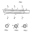
- the catheter tube 10 consists of a tissue-compatible elastic material.
- the insert body 11 is inserted into the front end of the catheter tube 10.
- the elongated insert body 11 has a fastening section 12 at its rear end and is designed as a plug 13 at its front end.
- the rear end 12 has the cross section shown in FIG. 2.
- the end 12 is essentially cylindrical, but flats are provided on opposite sides to form longitudinal channels 14 between the insert body and the wall of the catheter tube 10.
- the peripheral regions of the end 12 which are in contact with the catheter tube 10 slightly expand the catheter tube 10, so that the insert body 11 is secured in position inside the catheter tube 10 by friction. If necessary, the insert body 11 can also be fixed in the catheter tube by gluing or another connection technique.
- the middle part 15 of the insert body 11 extends between the end 12 and the front plug 13.
- the insert body 11 according to FIG. 3 has a cross section that is smaller than the cross section of the catheter lumen.
- the plug 13, which forms the front end of the insert body 11, is cylindrical and on its outer surface lies the front end of the catheter tube 10 radial tension.
- the catheter tube 10 is not or only partially fixed to the plug 13 so that it can lift off at least on a partial area of the circumference of the plug 13 if an excess pressure occurs in the interior of the catheter tube. The pressure medium can then escape through the front end 18 around the plug 13.
- the plug 13 projects beyond the front end 18 of the catheter tube and is designed as a rounded tip 19 at its end.
- the insert body 11 is in one piece, e.g. made of plastic. It consists of solid material.
- the largest outer diameter of the rear region 12 and the central region 15 is substantially equal to the outer diameter of the plug 13. This outer diameter is slightly larger than the inner diameter of the catheter tube 10, so that the catheter tube is slightly expanded by the insert body 11.
- the front edge 20 of the catheter tube 10 is beveled outwards, so that it forms a lip which clings to the stopper 13. This increases the sealing effect against external pressure.
- An infusion solution to be supplied to the patient is introduced into the catheter and flows through the longitudinal channels 14 past the rear end 12 of the insert body and into the longitudinal channels 17 of the middle part 15.
- the pressure prevailing in the catheter lifts the front end of the catheter tube off the stopper 13, so that the infusion solution ends can escape from the catheter tube.
- body fluid cannot penetrate into the catheter tube due to the sealing effect of the front catheter end enclosing the plug 13.
Landscapes
- Health & Medical Sciences (AREA)
- Life Sciences & Earth Sciences (AREA)
- Biophysics (AREA)
- Pulmonology (AREA)
- Engineering & Computer Science (AREA)
- Anesthesiology (AREA)
- Biomedical Technology (AREA)
- Heart & Thoracic Surgery (AREA)
- Hematology (AREA)
- Animal Behavior & Ethology (AREA)
- General Health & Medical Sciences (AREA)
- Public Health (AREA)
- Veterinary Medicine (AREA)
- Infusion, Injection, And Reservoir Apparatuses (AREA)
- Media Introduction/Drainage Providing Device (AREA)
Applications Claiming Priority (2)
| Application Number | Priority Date | Filing Date | Title |
|---|---|---|---|
| DE3540949 | 1985-11-19 | ||
| DE19853540949 DE3540949C1 (de) | 1985-11-19 | 1985-11-19 | Katheter |
Publications (2)
| Publication Number | Publication Date |
|---|---|
| EP0223003A2 true EP0223003A2 (fr) | 1987-05-27 |
| EP0223003A3 EP0223003A3 (fr) | 1987-08-19 |
Family
ID=6286348
Family Applications (1)
| Application Number | Title | Priority Date | Filing Date |
|---|---|---|---|
| EP19860112610 Withdrawn EP0223003A3 (fr) | 1985-11-19 | 1986-09-11 | Cathéter |
Country Status (4)
| Country | Link |
|---|---|
| US (1) | US4759752A (fr) |
| EP (1) | EP0223003A3 (fr) |
| JP (1) | JPS62129063A (fr) |
| DE (1) | DE3540949C1 (fr) |
Families Citing this family (21)
| Publication number | Priority date | Publication date | Assignee | Title |
|---|---|---|---|---|
| DE3721299A1 (de) * | 1987-06-27 | 1989-01-12 | Braun Melsungen Ag | Kathetervorrichtung |
| JPH047915U (fr) * | 1990-05-14 | 1992-01-24 | ||
| US5120316A (en) * | 1990-09-28 | 1992-06-09 | Akzo N.V. | Urethral catheter and catheterization process |
| US5163921A (en) * | 1990-10-04 | 1992-11-17 | Feiring Andrew J | Valved perfusion cardiovascular catheters |
| US5304155A (en) * | 1992-07-14 | 1994-04-19 | Cook Pacemaker Corporation | Valved catheter |
| DE4330089C2 (de) * | 1993-09-06 | 1995-06-22 | Gsf Forschungszentrum Umwelt | Katheter |
| US5807356A (en) * | 1994-01-18 | 1998-09-15 | Vasca, Inc. | Catheter with valve |
| US6053901A (en) * | 1994-01-18 | 2000-04-25 | Vasca, Inc. | Subcutaneously implanted cannula and method for arterial access |
| US5562617A (en) * | 1994-01-18 | 1996-10-08 | Finch, Jr.; Charles D. | Implantable vascular device |
| US6042569A (en) * | 1994-01-18 | 2000-03-28 | Vasca, Inc. | Subcutaneously implanted cannula and methods for vascular access |
| US5660205A (en) * | 1994-12-15 | 1997-08-26 | Epstein; Alan B. | One-way valve |
| US5728078A (en) * | 1996-03-19 | 1998-03-17 | Powers Dental & Medical Technologies Inc. | Medical suctioning bacteria valve and related method |
| US5989206A (en) | 1997-10-31 | 1999-11-23 | Biolink Corporation | Apparatus and method for the dialysis of blood |
| US6129707A (en) | 1998-01-21 | 2000-10-10 | Advanced Cardiovascular Systems, Inc. | Intravascular catheter with expanded distal tip |
| US6039305A (en) * | 1998-01-21 | 2000-03-21 | K-2 Corporation | Bite valve for hydration bladder |
| US7217251B2 (en) * | 2004-04-22 | 2007-05-15 | Medtronic, Inc. | Pressure relief methods in a medical catheter system |
| EP1747038B8 (fr) * | 2004-04-22 | 2009-04-08 | Metronic, Inc | Methodes diagnostiques pour des systemes catheters a ramifications |
| US8273082B2 (en) * | 2007-12-21 | 2012-09-25 | St. Jude Medical, Atrial Fibrillation Division, Inc. | Irrigated ablation catheter assembly having a flow member to create parallel external flow |
| WO2010090858A2 (fr) * | 2009-01-21 | 2010-08-12 | Medtronic, Inc. | Systèmes cathéters comportant des réducteurs de débit |
| US9539382B2 (en) | 2013-03-12 | 2017-01-10 | Medtronic, Inc. | Stepped catheters with flow restrictors and infusion systems using the same |
| JP6533578B2 (ja) * | 2014-12-01 | 2019-06-19 | キュラコ・インコーポレイテッドCURACO,Inc. | 人体対向開口部が形成された男性用モジュールを含む排泄物処理装置 |
Family Cites Families (12)
| Publication number | Priority date | Publication date | Assignee | Title |
|---|---|---|---|---|
| DE1704133U (de) * | 1955-05-11 | 1955-08-04 | Metallwerke Adolf Hopf K G | Kanuelle. |
| US3384113A (en) * | 1965-11-03 | 1968-05-21 | Gen Dynamics Corp | Relief valve |
| US3534771A (en) * | 1967-10-30 | 1970-10-20 | Eaton Yale & Towne | Valve assembly |
| US3841308A (en) * | 1973-10-15 | 1974-10-15 | Medical Evaluation Devices & I | Distally valved catheter device |
| GB1443247A (en) * | 1974-03-05 | 1976-07-21 | Mettoy Co Ltd | Non-return valves |
| DE2803094A1 (de) * | 1978-01-25 | 1979-07-26 | Hoechst Ag | Trachealtubus mit ueberdruckventil |
| DE2927788A1 (de) * | 1978-08-04 | 1980-02-21 | Wallace Ltd H G | Verbesserungen an intravaskulaeren kathetern |
| NZ193280A (en) * | 1979-04-13 | 1981-05-15 | Univ Minnesota | Check valve catheter tip for unidirectional flow |
| US4657536A (en) * | 1979-04-13 | 1987-04-14 | Regents Of The University Of Minnesota | Check valve catheter |
| US4346704A (en) * | 1980-09-09 | 1982-08-31 | Baxter Travenol Laboratories, Inc. | Sleeve valve for parenteral solution device |
| DE3035748C2 (de) * | 1980-09-22 | 1986-01-02 | Siemens AG, 1000 Berlin und 8000 München | Infusionsgerät |
| US4445896A (en) * | 1982-03-18 | 1984-05-01 | Cook, Inc. | Catheter plug |
-
1985
- 1985-11-19 DE DE19853540949 patent/DE3540949C1/de not_active Expired
-
1986
- 1986-09-11 EP EP19860112610 patent/EP0223003A3/fr not_active Withdrawn
- 1986-11-14 US US06/930,784 patent/US4759752A/en not_active Expired - Fee Related
- 1986-11-19 JP JP61276379A patent/JPS62129063A/ja active Pending
Also Published As
| Publication number | Publication date |
|---|---|
| DE3540949C1 (de) | 1987-01-02 |
| JPS62129063A (ja) | 1987-06-11 |
| US4759752A (en) | 1988-07-26 |
| EP0223003A3 (fr) | 1987-08-19 |
Similar Documents
| Publication | Publication Date | Title |
|---|---|---|
| EP0223003A2 (fr) | Cathéter | |
| EP1032446B2 (fr) | Configuration d'aiguille | |
| DE69009734T2 (de) | Saugvorrichtung. | |
| DE3809127C1 (fr) | ||
| DE19911911B4 (de) | Verschlußelement für ein Endoskop | |
| DE69225609T2 (de) | Kanülen-halterung mit drehbarer schutzhülle | |
| DE69323563T2 (de) | Sonde für dialyse | |
| DE2845643A1 (de) | Katheteranschlusskopf mit mindestens einem kanal in einem grundkoerper | |
| DE7821043U1 (de) | Ventil, insbesondere miniaturventil fuer medizinische zwecke | |
| DE2803395A1 (de) | Befestigungsvorrichtung fuer eine anordnung zum anlegen eines katheters | |
| DE3522558A1 (de) | Dichtungsprofil | |
| DE4309088A1 (de) | Ortsfest einbaubare Scheibe für Kraftfahrzeuge | |
| EP0054728B1 (fr) | Dispositif de cathétérisme | |
| DE3147609A1 (de) | "einfuehrungsvorrichtung zum einbringen langgestreckter gegenstaende in ein blutgefaess" | |
| DE3428311A1 (de) | Auslaufelement, insbesondere zur medizinischen verwendung | |
| DE8306378U1 (de) | Koecher zur aufnahme eines roehrchenschreibers | |
| DE2902378B2 (de) | Dichtungsanordnung für den Führungsbolzen einer Schwimmsattel-Teilbelag-Scheibenbremse | |
| DE3207795A1 (de) | Dicht- und abschlussleiste | |
| DE3140192C2 (de) | Katheter | |
| DE3541335C2 (de) | Blutentnahmevorrichtung | |
| EP1637178B1 (fr) | Soupape pour appareils médicaux | |
| DE2213183C2 (de) | Abdeckung für Mauern od.dgl | |
| DE1924410A1 (de) | Muffenverbindung fuer Rohre | |
| DE3514526A1 (de) | Tuersteuervorrichtung | |
| DE8814492U1 (de) | Verschlußkappe für Schreib- oder ähnliche Geräte |
Legal Events
| Date | Code | Title | Description |
|---|---|---|---|
| PUAI | Public reference made under article 153(3) epc to a published international application that has entered the european phase |
Free format text: ORIGINAL CODE: 0009012 |
|
| AK | Designated contracting states |
Kind code of ref document: A2 Designated state(s): AT BE CH DE FR GB IT LI LU NL SE |
|
| PUAL | Search report despatched |
Free format text: ORIGINAL CODE: 0009013 |
|
| AK | Designated contracting states |
Kind code of ref document: A3 Designated state(s): AT BE CH DE FR GB IT LI LU NL SE |
|
| 17P | Request for examination filed |
Effective date: 19870910 |
|
| RAP1 | Party data changed (applicant data changed or rights of an application transferred) |
Owner name: B. BRAUN-SSC AG |
|
| 17Q | First examination report despatched |
Effective date: 19890516 |
|
| STAA | Information on the status of an ep patent application or granted ep patent |
Free format text: STATUS: THE APPLICATION IS DEEMED TO BE WITHDRAWN |
|
| 18D | Application deemed to be withdrawn |
Effective date: 19891205 |
|
| RIN1 | Information on inventor provided before grant (corrected) |
Inventor name: STOEBER, HERBERT |