EP0218795B1 - Dispositif de réglage pour fixation de ski - Google Patents
Dispositif de réglage pour fixation de ski Download PDFInfo
- Publication number
- EP0218795B1 EP0218795B1 EP86108718A EP86108718A EP0218795B1 EP 0218795 B1 EP0218795 B1 EP 0218795B1 EP 86108718 A EP86108718 A EP 86108718A EP 86108718 A EP86108718 A EP 86108718A EP 0218795 B1 EP0218795 B1 EP 0218795B1
- Authority
- EP
- European Patent Office
- Prior art keywords
- detent
- adjusting device
- ski
- pivot
- cradle
- Prior art date
- Legal status (The legal status is an assumption and is not a legal conclusion. Google has not performed a legal analysis and makes no representation as to the accuracy of the status listed.)
- Expired
Links
Images

Classifications
-
- A—HUMAN NECESSITIES
- A63—SPORTS; GAMES; AMUSEMENTS
- A63C—SKATES; SKIS; ROLLER SKATES; DESIGN OR LAYOUT OF COURTS, RINKS OR THE LIKE
- A63C9/00—Ski bindings
- A63C9/005—Ski bindings with means for adjusting the position of a shoe holder or of the complete binding relative to the ski
Definitions
- the invention relates to an adjusting device according to the preamble of claim 1.
- an adjusting device in which a bolt is guided in a transverse groove of a ski binding part, the end of which engages in one of the tooth gaps of a guide rail and which is supported by a cam which is guided by a Lever is pivotable, can be moved.
- a slide is guided on a guide rail, which is provided with an inwardly directed toothed rack, in which a locking element is pivotally mounted on an axis running perpendicular to the upper side of the ski, with its teeth the rack can be engaged.
- the latching element is coupled to a slide which is displaceable transversely to the longitudinal direction of the ski and can be latched by a spring. The slide makes it possible to disengage the locking element from the toothed rack.
- the invention has for its object to eliminate the disadvantages of all known embodiments and to provide an adjusting device in which a reliable locking of the teeth of the locking member is ensured even with prolonged use of the adjusting device.
- the latching element is positively fixed in the latched state by the intermediate member, so that unintentional opening of the adjusting device is excluded.
- the measure of claim 2 allows a slight deformation of the intermediate member, whereby the operation is facilitated.
- the solution specified in claim 3 is robust in its structure and can also be easily manufactured.
- the subject of claim 4 prevents unintentional opening of the adjusting device in the driving position with certainty.
- a split version of the locking element is not absolutely necessary for the function of the adjusting device.
- an undivided design requires an ample amount of play between the locking member and the slide, which is sometimes undesirable.
- the game can be considerably reduced, since the area of the latching member that bears the latching teeth is no longer pivoted, but is only shifted.
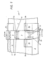
- Fig. 1 is a plan view of an adjusting device in the locked position and Fig. 2 is a section along the line 11 - II in Fig. 1. In Fig. 3 is shown a section through the adjusting device, which is in the released position.
- the adjusting device is designated 1 in its entirety. It has a base plate 2 running in the longitudinal direction of the ski, and a slide 3 guided along the same. In the base plate 2, a groove 2a extending in the longitudinal direction thereof is formed, in which a toothed strip 4 is located.
- a latching element 5 is placed on the carriage 3, its end 5a, which is bent through 180 ° and carries the latching teeth 5c, engages in the groove 4.
- the locking member 5 carries two bearing eyes 5b, in which an axis 6 is arranged. On this axis 6, a pivot part 7 is mounted, which can be pivoted by hand.
- the pivoting part 7 On its underside, the pivoting part 7 carries two bearing blocks 8 provided with slots, in which the crank 9a of an intermediate member 9 designed as a crankshaft is arranged.
- the main bearings 9b of the intermediate member 9 are located in tabs 3a of the sheet which are bent through 180 ° Carriage 3.
- the tabs 3a are bent slightly upwards and thus form a lateral guide for the latching member 5.
- the free end 7a of the pivoting part 7, which is bent through 90 °, projects beyond the carriage 3 and serves to attack the hand. From the side wall of the carriage 3 adjacent to the end 7a, two projections 3b are formed which protect the end 7a against damage.
- the adjusting device 1 While driving, the adjusting device 1 is in the position shown in FIGS. 1 and 2.
- the locking teeth 5c of the locking member 5 engage in the toothed rack 4 (see FIG. 3), and the crank 9a of the intermediate member 9 is located beyond the dead center, namely below that plane which passes through the axis 6 and parallel to the base plate 2 runs.
- the pivoting part 7 therefore acts in the manner of a tensioner, which presses the teeth 5c of the locking member 5 into the toothed strip 4 under a predetermined force.
- the end 7a of the swivel part 7 is raised by hand.
- the crank 9a of the intermediate member 9 is pivoted upward above the dead center position.
- the intermediate member 9 may not be articulated on the swivel part 7, but rather on the latching member 5 itself.
Claims (5)
Applications Claiming Priority (2)
| Application Number | Priority Date | Filing Date | Title |
|---|---|---|---|
| AT0199685A AT384170B (de) | 1985-07-05 | 1985-07-05 | Verstelleinrichtung fuer skibindungen |
| AT1996/85 | 1985-07-05 |
Publications (3)
| Publication Number | Publication Date |
|---|---|
| EP0218795A2 EP0218795A2 (fr) | 1987-04-22 |
| EP0218795A3 EP0218795A3 (en) | 1987-08-12 |
| EP0218795B1 true EP0218795B1 (fr) | 1988-11-02 |
Family
ID=3525582
Family Applications (1)
| Application Number | Title | Priority Date | Filing Date |
|---|---|---|---|
| EP86108718A Expired EP0218795B1 (fr) | 1985-07-05 | 1986-06-26 | Dispositif de réglage pour fixation de ski |
Country Status (5)
| Country | Link |
|---|---|
| US (1) | US4699397A (fr) |
| EP (1) | EP0218795B1 (fr) |
| JP (1) | JPS628773A (fr) |
| AT (1) | AT384170B (fr) |
| DE (1) | DE3661052D1 (fr) |
Families Citing this family (4)
| Publication number | Priority date | Publication date | Assignee | Title |
|---|---|---|---|---|
| FR2672506B1 (fr) * | 1991-02-08 | 1993-04-30 | Salomon Sa | Fixation de securite pour ski. |
| ATE130525T1 (de) * | 1991-11-08 | 1995-12-15 | Salomon Sa | Vorrichtung zur längenverstellung einer alpinen bindung. |
| FR2739572B1 (fr) * | 1995-10-10 | 1997-12-19 | Look Fixations Sa | Embase de fixation de ski reglable longitudinalement |
| FR2835759B1 (fr) * | 2002-02-11 | 2004-05-14 | Look Fixations Sa | Embase de fixation de ski reglable |
Family Cites Families (10)
| Publication number | Priority date | Publication date | Assignee | Title |
|---|---|---|---|---|
| US3125349A (en) * | 1960-10-20 | 1964-03-17 | Schweizer | |
| CH469492A (fr) * | 1967-12-04 | 1969-03-15 | Reuge Sa | Dispositif de fixation de ski comprenant une butée de sécurité avant et/ou une butée de sécurité arrière réglable en position axiale sur le ski |
| FR2206960B1 (fr) * | 1972-11-20 | 1976-06-04 | Beyl Jean Joseph Alfred | |
| AT327066B (de) * | 1973-07-04 | 1976-01-12 | Smolka & Co Wiener Metall | Verstelleinrichtung an skibindungen |
| AT330633B (de) * | 1974-09-13 | 1976-07-12 | Smolka & Co Wiener Metall | Verstelleinrichtung fur skibindungen |
| FR2303573A1 (fr) * | 1975-03-11 | 1976-10-08 | Mitchell Sa | Dispositif de retenue d'une extremite d'une chaussure sur une fixation de ski |
| JPS5630850Y2 (fr) * | 1980-07-05 | 1981-07-22 | ||
| AT369657B (de) * | 1980-12-19 | 1983-01-25 | Tyrolia Freizeitgeraete | Verstelleinrichtung fuer einen backen |
| AT371731B (de) * | 1981-08-20 | 1983-07-25 | Tyrolia Freizeitgeraete | Vorrichtung zur laengsverstellung von skibindungsteilen |
| US4500108A (en) * | 1983-02-16 | 1985-02-19 | Johnson Iii Luvern C | Convertible ski device |
-
1985
- 1985-07-05 AT AT0199685A patent/AT384170B/de not_active IP Right Cessation
-
1986
- 1986-06-26 DE DE8686108718T patent/DE3661052D1/de not_active Expired
- 1986-06-26 EP EP86108718A patent/EP0218795B1/fr not_active Expired
- 1986-07-01 US US06/880,865 patent/US4699397A/en not_active Expired - Fee Related
- 1986-07-04 JP JP61156355A patent/JPS628773A/ja active Pending
Also Published As
| Publication number | Publication date |
|---|---|
| US4699397A (en) | 1987-10-13 |
| JPS628773A (ja) | 1987-01-16 |
| AT384170B (de) | 1987-10-12 |
| EP0218795A3 (en) | 1987-08-12 |
| ATA199685A (de) | 1987-03-15 |
| DE3661052D1 (en) | 1988-12-08 |
| EP0218795A2 (fr) | 1987-04-22 |
Similar Documents
| Publication | Publication Date | Title |
|---|---|---|
| DE4021277C2 (de) | Handgeführtes Arbeitsgerät mit verstellbarem Handgriff | |
| DE2954446C2 (de) | Skibindung | |
| DE3905600C2 (de) | Verfahren zum Schneiden von Papier sowie Papierschneidemaschine | |
| EP0093318B1 (fr) | Machine à découenner | |
| DE3924915C2 (de) | Langlaufskibindung der Scharnierbauart | |
| DE3744688C2 (fr) | ||
| EP0256245B1 (fr) | Porte-outil pour une machine à plier ou analogue | |
| DE2359490C3 (de) | Vorderer Bindungsteil einer Sicherheitsbindung fur Ski | |
| EP0218795B1 (fr) | Dispositif de réglage pour fixation de ski | |
| DE2322578B2 (de) | Vorrichtung zum Festlegen von unter einem Flugzeug mitzuführenden Lasten | |
| CH688023A5 (de) | Bindungseinrichtung zwischen einem Schuh und einem Sportgeraet | |
| DE3145708C2 (de) | Umhängenadel für Flachstrickmaschinen | |
| EP0169315B1 (fr) | Elément de fixation de ski en particulier mâchoire avant | |
| DE3152953C2 (de) | Sicherheitsskibindung | |
| DE3520027C2 (fr) | ||
| EP0305767A2 (fr) | Dispositif pour la fixation d'un chariot sur une machine-outil | |
| EP0189562B1 (fr) | Talonnière pour fixation de ski | |
| DE2065939C3 (de) | Nähmaschine | |
| DE2311156C2 (de) | Auslöseskibindung | |
| DE3042829C2 (de) | Betätigungsgetriebe für Treibstangenbeschläge o.dgl. | |
| DE3027343C2 (de) | Schwertantrieb für Falzmaschinen | |
| DE3141021C2 (fr) | ||
| DE3634424A1 (de) | Handschleifmaschine | |
| DE1578999C3 (de) | Andrück- bzw. Festhaltebacken für eine Sicherheits-Skibindung | |
| AT371731B (de) | Vorrichtung zur laengsverstellung von skibindungsteilen |
Legal Events
| Date | Code | Title | Description |
|---|---|---|---|
| PUAI | Public reference made under article 153(3) epc to a published international application that has entered the european phase |
Free format text: ORIGINAL CODE: 0009012 |
|
| AK | Designated contracting states |
Kind code of ref document: A2 Designated state(s): CH DE FR LI |
|
| PUAL | Search report despatched |
Free format text: ORIGINAL CODE: 0009013 |
|
| AK | Designated contracting states |
Kind code of ref document: A3 Designated state(s): CH DE FR LI |
|
| 17P | Request for examination filed |
Effective date: 19870808 |
|
| 17Q | First examination report despatched |
Effective date: 19871210 |
|
| GRAA | (expected) grant |
Free format text: ORIGINAL CODE: 0009210 |
|
| AK | Designated contracting states |
Kind code of ref document: B1 Designated state(s): CH DE FR LI |
|
| REF | Corresponds to: |
Ref document number: 3661052 Country of ref document: DE Date of ref document: 19881208 |
|
| ET | Fr: translation filed | ||
| PLBE | No opposition filed within time limit |
Free format text: ORIGINAL CODE: 0009261 |
|
| STAA | Information on the status of an ep patent application or granted ep patent |
Free format text: STATUS: NO OPPOSITION FILED WITHIN TIME LIMIT |
|
| 26N | No opposition filed | ||
| REG | Reference to a national code |
Ref country code: CH Ref legal event code: PUE Owner name: AMF CORPORATION TRANSFER- HTM SPORTS CORP. Ref country code: CH Ref legal event code: PFA Free format text: TMC CORPORATION, RUESSENSTRASSE 16, WALTERSWIL ZG, BAAR |
|
| REG | Reference to a national code |
Ref country code: FR Ref legal event code: TP Ref country code: FR Ref legal event code: CD |
|
| REG | Reference to a national code |
Ref country code: CH Ref legal event code: PUE Owner name: HTM SPORT- UND FREIZEITGERAETE GMBH |
|
| REG | Reference to a national code |
Ref country code: FR Ref legal event code: TP |
|
| REG | Reference to a national code |
Ref country code: CH Ref legal event code: PFA Free format text: HTM SPORT- UND FREIZEITGERAETE AKTIENGESELLSCHAFT |
|
| REG | Reference to a national code |
Ref country code: FR Ref legal event code: TP |
|
| PGFP | Annual fee paid to national office [announced via postgrant information from national office to epo] |
Ref country code: DE Payment date: 19950413 Year of fee payment: 10 |
|
| PGFP | Annual fee paid to national office [announced via postgrant information from national office to epo] |
Ref country code: FR Payment date: 19950418 Year of fee payment: 10 |
|
| PGFP | Annual fee paid to national office [announced via postgrant information from national office to epo] |
Ref country code: CH Payment date: 19950630 Year of fee payment: 10 |
|
| PG25 | Lapsed in a contracting state [announced via postgrant information from national office to epo] |
Ref country code: LI Effective date: 19960630 Ref country code: CH Effective date: 19960630 |
|
| REG | Reference to a national code |
Ref country code: CH Ref legal event code: PL |
|
| PG25 | Lapsed in a contracting state [announced via postgrant information from national office to epo] |
Ref country code: FR Effective date: 19970228 |
|
| PG25 | Lapsed in a contracting state [announced via postgrant information from national office to epo] |
Ref country code: DE Effective date: 19970301 |
|
| REG | Reference to a national code |
Ref country code: FR Ref legal event code: ST |