EP0218795B1 - Adjusting device for a ski binding - Google Patents
Adjusting device for a ski binding Download PDFInfo
- Publication number
- EP0218795B1 EP0218795B1 EP86108718A EP86108718A EP0218795B1 EP 0218795 B1 EP0218795 B1 EP 0218795B1 EP 86108718 A EP86108718 A EP 86108718A EP 86108718 A EP86108718 A EP 86108718A EP 0218795 B1 EP0218795 B1 EP 0218795B1
- Authority
- EP
- European Patent Office
- Prior art keywords
- detent
- adjusting device
- ski
- pivot
- cradle
- Prior art date
- Legal status (The legal status is an assumption and is not a legal conclusion. Google has not performed a legal analysis and makes no representation as to the accuracy of the status listed.)
- Expired
Links
Images

Classifications
-
- A—HUMAN NECESSITIES
- A63—SPORTS; GAMES; AMUSEMENTS
- A63C—SKATES; SKIS; ROLLER SKATES; DESIGN OR LAYOUT OF COURTS, RINKS OR THE LIKE
- A63C9/00—Ski bindings
- A63C9/005—Ski bindings with means for adjusting the position of a shoe holder or of the complete binding relative to the ski
Definitions
- the invention relates to an adjusting device according to the preamble of claim 1.
- an adjusting device in which a bolt is guided in a transverse groove of a ski binding part, the end of which engages in one of the tooth gaps of a guide rail and which is supported by a cam which is guided by a Lever is pivotable, can be moved.
- a slide is guided on a guide rail, which is provided with an inwardly directed toothed rack, in which a locking element is pivotally mounted on an axis running perpendicular to the upper side of the ski, with its teeth the rack can be engaged.
- the latching element is coupled to a slide which is displaceable transversely to the longitudinal direction of the ski and can be latched by a spring. The slide makes it possible to disengage the locking element from the toothed rack.
- the invention has for its object to eliminate the disadvantages of all known embodiments and to provide an adjusting device in which a reliable locking of the teeth of the locking member is ensured even with prolonged use of the adjusting device.
- the latching element is positively fixed in the latched state by the intermediate member, so that unintentional opening of the adjusting device is excluded.
- the measure of claim 2 allows a slight deformation of the intermediate member, whereby the operation is facilitated.
- the solution specified in claim 3 is robust in its structure and can also be easily manufactured.
- the subject of claim 4 prevents unintentional opening of the adjusting device in the driving position with certainty.
- a split version of the locking element is not absolutely necessary for the function of the adjusting device.
- an undivided design requires an ample amount of play between the locking member and the slide, which is sometimes undesirable.
- the game can be considerably reduced, since the area of the latching member that bears the latching teeth is no longer pivoted, but is only shifted.
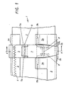
- Fig. 1 is a plan view of an adjusting device in the locked position and Fig. 2 is a section along the line 11 - II in Fig. 1. In Fig. 3 is shown a section through the adjusting device, which is in the released position.
- the adjusting device is designated 1 in its entirety. It has a base plate 2 running in the longitudinal direction of the ski, and a slide 3 guided along the same. In the base plate 2, a groove 2a extending in the longitudinal direction thereof is formed, in which a toothed strip 4 is located.
- a latching element 5 is placed on the carriage 3, its end 5a, which is bent through 180 ° and carries the latching teeth 5c, engages in the groove 4.
- the locking member 5 carries two bearing eyes 5b, in which an axis 6 is arranged. On this axis 6, a pivot part 7 is mounted, which can be pivoted by hand.
- the pivoting part 7 On its underside, the pivoting part 7 carries two bearing blocks 8 provided with slots, in which the crank 9a of an intermediate member 9 designed as a crankshaft is arranged.
- the main bearings 9b of the intermediate member 9 are located in tabs 3a of the sheet which are bent through 180 ° Carriage 3.
- the tabs 3a are bent slightly upwards and thus form a lateral guide for the latching member 5.
- the free end 7a of the pivoting part 7, which is bent through 90 °, projects beyond the carriage 3 and serves to attack the hand. From the side wall of the carriage 3 adjacent to the end 7a, two projections 3b are formed which protect the end 7a against damage.
- the adjusting device 1 While driving, the adjusting device 1 is in the position shown in FIGS. 1 and 2.
- the locking teeth 5c of the locking member 5 engage in the toothed rack 4 (see FIG. 3), and the crank 9a of the intermediate member 9 is located beyond the dead center, namely below that plane which passes through the axis 6 and parallel to the base plate 2 runs.
- the pivoting part 7 therefore acts in the manner of a tensioner, which presses the teeth 5c of the locking member 5 into the toothed strip 4 under a predetermined force.
- the end 7a of the swivel part 7 is raised by hand.
- the crank 9a of the intermediate member 9 is pivoted upward above the dead center position.
- the intermediate member 9 may not be articulated on the swivel part 7, but rather on the latching member 5 itself.
Description
Die Erfindung bezieht sich auf eine Verstelleinrichtung gemäß dem Oberbegriff des Patentanspruches 1.The invention relates to an adjusting device according to the preamble of
Eine derartige Verstelleinrichtung ist in der AT-PS 350 449 bereits beschrieben. Bei dieser Verstelleinrichtung steht das Rastglied unter dem Einfluß einer Druckfeder, welche die Zähne des Rastgliedes in die Zahnleiste drückt; die Verriegelung ist sohin kraftschlüssig. Da die Zähne in der Draufsicht im allgemeinen die Gestalt von gleichschenkeligen Dreiecken haben, kann es vorkommen, daß bei allzugroßem Druck auf den Bindungsteil die Kraft der Druckfeder überwunden wird und das Rastglied entlang der Zahnleiste verschoben wird, was zu einer Beschädigung der Zähne sowohl des Rastgliedes als auch der Zahnleiste führt.Such an adjustment device is already described in AT-PS 350 449. In this adjusting device, the locking member is under the influence of a compression spring which presses the teeth of the locking member into the rack; the locking is thus non-positive. Since the teeth generally have the shape of isosceles triangles in plan view, it can happen that if the pressure on the binding part is too great, the force of the compression spring is overcome and the locking element is displaced along the toothed strip, which leads to damage to the teeth of both the locking element as well as the rack.
In den Fig. 15 bis 17 der CH-PS 469 492 ist eine Verstelleinrichtung dargestellt, bei der in einer quer verlaufenden Nut eines Skibindungsteiles ein Riegel geführt wird, dessen Ende in eine der Zahnlücken einer Führungsschiene eingreift und der durch einen Nocken, welcher durch einen Hebel verschwenkbar ist, verschoben werden kann.15 to 17 of CH-PS 469 492, an adjusting device is shown, in which a bolt is guided in a transverse groove of a ski binding part, the end of which engages in one of the tooth gaps of a guide rail and which is supported by a cam which is guided by a Lever is pivotable, can be moved.
Bei dieser Konstruktion ist nachteiligerweise ein Verriegeln nur möglich, wenn sich Riegel und Gehäuse einander genau gegenüberstehen, wodurch zum Verrasten ungedingt zwei Hände benötigt werden: eine die den Backenkörper führt und eine zweite, die den Hebel betätigt.In this construction, locking is disadvantageously only possible if the latch and housing are exactly opposite one another, which means that two hands are absolutely necessary for locking: one which guides the jaw body and a second which actuates the lever.
Bei der Verstelleinrichtung gemäß der DE-OS 1 954 512 ist auf einer Führungsschiene, die mit einer nach innen gerichteten Zahnleiste versehen ist, ein Schlitten geführt, in dem auf einer senkrecht zur Skioberseite verlaufenden Achse ein Rastelement schwenkbar gelagert ist, das mit seinen Zähnen mit der Zahnleiste in Eingriff gebracht werden kann. Das Rastelement ist mit einem Schieber gekoppelt, der quer zur Skilängsrichtung verschiebbar und durch eine Feder verrastbar ist. Durch den Schieber ist es möglich, das Rastelement außer Eingriff mit der Zahnleiste zu bringen.In the adjustment device according to DE-OS 1 954 512, a slide is guided on a guide rail, which is provided with an inwardly directed toothed rack, in which a locking element is pivotally mounted on an axis running perpendicular to the upper side of the ski, with its teeth the rack can be engaged. The latching element is coupled to a slide which is displaceable transversely to the longitudinal direction of the ski and can be latched by a spring. The slide makes it possible to disengage the locking element from the toothed rack.
Diese Konstruktion wieder hat den Nachteil, daß infolge der in Draufsicht dreieckigen Zähne im Betrieb das Rastelement einem Drehmoment unterworfen wird, das es mit der Zahnleiste außer Eingriff zu bringen sucht. Durch dieses Drehmoment wird aber der Flächendruck zwischen der Rastnase des Rastelementes und der Ausnehmung im Schieber, in welche die Rastnase eingreift, so groß, daß es nach längerem Gebrauch der Verstelleinrichtung zu Verformungen kommt, welche eine unbeabsichtigte Entriegelung von Rastelement und Zahnleiste zur Folge haben.This construction again has the disadvantage that, due to the teeth which are triangular in plan view, the latching element is subjected to a torque during operation which it tries to disengage from the toothed rack. By this torque, however, the surface pressure between the latching lug of the latching element and the recess in the slide, in which the latching lug engages, is so great that, after prolonged use of the adjusting device, deformations occur which result in inadvertent unlocking of the latching element and toothed rack.
Die Erfindung stellt sich die Aufgabe, die Nachteile aller bekannten Ausführungsformen zu beseitigen und eine Verstelleinrichtung zu schaffen, bei der eine zuverlässige Verriegelung der Zähne des Rastgliedes auch bei längerem Gebrauch der Verstelleinrichtung gewährleistet ist.The invention has for its object to eliminate the disadvantages of all known embodiments and to provide an adjusting device in which a reliable locking of the teeth of the locking member is ensured even with prolonged use of the adjusting device.
Ausgehend von einer Verstelleinrichtung gemäß dem Oberbegriff des Anspruches 1 wird diese Aufgabe durch die Merkmale des kennzeichnenden Teiles dieses Anspruches gelöst. Durch das Zwischenglied wird das Rastglied im verrastetem Zustand zwangsschlüssig festgelegt, so daß ein unbeabsichtigtes Öffnen der Verstelleinrichtung ausgeschlossen ist.Starting from an adjustment device according to the preamble of
Durch die Maßnahme des Anspruches 2 wird eine geringfügige Verformung des Zwischengliedes ermöglicht, wodurch die Betätigung erleichtert wird.The measure of
Für die Ausbildung des Zwischengliedes bieten sich verschiedene Lösungen an. Die im Anspruch 3 angegebene Lösung ist in ihrem Aufbau robust und läßt sich außerdem einfach herstellen.Various solutions are available for training the pontic. The solution specified in
Durch den Gegenstand des Anspruches 4 wird ein unbeabsichtigtes Öffnen der Verstelleinrichtung in der Fahrtstellung mit Sicherheit verhindert.The subject of
Für die Funktion der Verstelleinrichtung ist eine geteilte Ausführung des Rastgliedes nicht unbedingt erforderlich. Allerdings setzt eine ungeteilte Ausführung ein reichlich bemessenes Spiel zwischen Rastglied und Schlitten voraus, was mitunter unerwünscht ist. Bei der erfindungsgemäßen Lösung nach Anspruch 5 kann das Spiel erheblich reduziert werden, da der die Rastzähne tragende Bereich des Rastgliedes nicht mehr verschwenkt, sondern nur noch verschoben wird.A split version of the locking element is not absolutely necessary for the function of the adjusting device. However, an undivided design requires an ample amount of play between the locking member and the slide, which is sometimes undesirable. In the solution according to the invention according to
Schließlich wird es durch die Maßnahme des Anspruches 6 möglich, den Schwenkwinkel des schwenkbaren Teiles des Rastgliedes klein zu halten.Finally, it becomes possible by the measure of
In der Zeichnung ist eine beispielsweise Ausführungsform des Erfindungsgegenstandes rein schematisch dargestellt. Fig. 1 ist eine Draufsicht auf eine Verstelleinrichtung in der verrasteten Lage und Fig. 2 ein Schnitt nach der Linie 11 - II in Fig. 1. In Fig. 3 ist ein Schnitt durch die Verstelleinrichtung wiedergegeben, die sich in der gelösten Lage befindet.In the drawing, an example embodiment of the subject matter of the invention is shown purely schematically. Fig. 1 is a plan view of an adjusting device in the locked position and Fig. 2 is a section along the line 11 - II in Fig. 1. In Fig. 3 is shown a section through the adjusting device, which is in the released position.
Die Verstelleinrichtung ist in ihrer Gesamtheit mit 1 bezeichnet. Sie besitzt eine in Skilängsrichtung verlaufende Grundplatte 2, und einen entlang derselben geführten Schlitten 3. In der Grundplatte 2 ist eine in Längsrichtung derselben verlaufende Nut 2a ausgebildet, in der sich eine Zahnleiste 4 befindet. Auf den Schlitten 3 ist ein Rastglied 5 aufgesetzt, dessen um 180° umgebogenes Ende 5a, das die Rastzähne 5c trägt, in die Nut 4 eingreift. Das Rastglied 5 trägt zwei Lageraugen 5b, in denen eine Achse 6 angeordnet ist. Auf dieser Achse 6 ist ein Schwenkteil 7 gelagert, der von Hand verschwenkt werden kann. An seiner Unterseite trägt der Schwenkteil 7 zwei mit Schlitzen versehene Lagerböcke 8, in denen die Kurbel 9a eines als Kurbelwelle ausgestalteten Zwischengliedes 9 angeordnet ist. Die Hauptlager 9b des Zwischengliedes 9 befinden sich in um 180° umgebogenen Lappen 3a des Schlittens 3. Die Lappen 3a sind etwas nach oben gebogen und bilden so eine seitliche Führung für das Rastglied 5. Das freie Ende 7a des Schwenkteiles 7, das um 90° umgebogen ist, ragt über den Schlitten 3 hinaus und dient zum Angriff der Hand. Aus der dem Ende 7a benachbarten Seitenwand des Schlittens 3 sind zwei Vorsprünge 3b ausgeprägt, welche das Ende 7a gegen Beschädigungen schützen.The adjusting device is designated 1 in its entirety. It has a
Während der Fahrt befindet sich die Verstelleinrichtung 1 in der in den Fig. 1 und 2 dargestellten Lage. In dieser greifen die Rastzähne 5c des Rastgliedes 5 in die Zahnleiste 4 ein (s. Fig. 3), und die Kurbel 9a des Zwischengliedes 9 befindet sich jenseits des Totpunktes, nämlich unterhalb jener Ebene, welche durch die Achse 6 und parallel zur Grundplatte 2 verläuft. Der Schwenkteil 7 wirkt daher nach Art eines Strammers, der die Zähne 5c des Rastgliedes 5 unter einer vorgegebene Kraft in die Zahnleiste 4 drückt.While driving, the adjusting
Soll die Verstelleinrichtung gelöst werden, so wird das Ende 7a des Schwenkteiles 7 von Hand angehoben. Dabei wird die Kurbel 9a des Zwischengliedes 9 über die Totpunktlage nach oben verschwenkt.If the adjusting device is to be released, the
Gleichzeitig wird das Rastglied in Fig. 3 nach links verschoben, so daß die Zähne 5c des Rastgliedes 5 die Zahnleiste 4 verlassen. Der Schlitten 3 kann nun entlang der Grundplatte 2 verschoben werden, bis die gewünschte Stellung des Schlittens 3 erreicht ist. Danach wird der Schwenkteil 7 von der Hand des Benützers niedergedrückt und der Verstellvorgang ist beendet.At the same time, the locking member in Fig. 3 is shifted to the left so that the
Alternativ zu der beschriebenen Ausführungsform kann das Zwischenglied 9 nicht am Schwenkteil 7, sondern am Rastglied 5 selbst angelenkt sein.As an alternative to the described embodiment, the
Claims (5)
Applications Claiming Priority (2)
| Application Number | Priority Date | Filing Date | Title |
|---|---|---|---|
| AT1996/85 | 1985-07-05 | ||
| AT0199685A AT384170B (en) | 1985-07-05 | 1985-07-05 | ADJUSTMENT FOR SKI BINDINGS |
Publications (3)
| Publication Number | Publication Date |
|---|---|
| EP0218795A2 EP0218795A2 (en) | 1987-04-22 |
| EP0218795A3 EP0218795A3 (en) | 1987-08-12 |
| EP0218795B1 true EP0218795B1 (en) | 1988-11-02 |
Family
ID=3525582
Family Applications (1)
| Application Number | Title | Priority Date | Filing Date |
|---|---|---|---|
| EP86108718A Expired EP0218795B1 (en) | 1985-07-05 | 1986-06-26 | Adjusting device for a ski binding |
Country Status (5)
| Country | Link |
|---|---|
| US (1) | US4699397A (en) |
| EP (1) | EP0218795B1 (en) |
| JP (1) | JPS628773A (en) |
| AT (1) | AT384170B (en) |
| DE (1) | DE3661052D1 (en) |
Families Citing this family (4)
| Publication number | Priority date | Publication date | Assignee | Title |
|---|---|---|---|---|
| FR2672506B1 (en) * | 1991-02-08 | 1993-04-30 | Salomon Sa | SECURITY FIXING FOR SKI. |
| EP0546260B1 (en) * | 1991-11-08 | 1995-11-22 | Salomon S.A. | Device for regulating the longitudinal position of an alpine binding |
| FR2739572B1 (en) * | 1995-10-10 | 1997-12-19 | Look Fixations Sa | LONGITUDINALLY ADJUSTABLE SKI FIXING BASE |
| FR2835759B1 (en) * | 2002-02-11 | 2004-05-14 | Look Fixations Sa | ADJUSTABLE SKI FIXING BASE |
Family Cites Families (10)
| Publication number | Priority date | Publication date | Assignee | Title |
|---|---|---|---|---|
| US3125349A (en) * | 1960-10-20 | 1964-03-17 | Schweizer | |
| CH469492A (en) * | 1967-12-04 | 1969-03-15 | Reuge Sa | Ski binding device comprising a front safety stopper and / or a rear safety stopper adjustable in the axial position on the ski |
| FR2206960B1 (en) * | 1972-11-20 | 1976-06-04 | Beyl Jean Joseph Alfred | |
| AT327066B (en) * | 1973-07-04 | 1976-01-12 | Smolka & Co Wiener Metall | ADJUSTMENT DEVICE ON SKI BINDINGS |
| AT330633B (en) * | 1974-09-13 | 1976-07-12 | Smolka & Co Wiener Metall | ADJUSTMENT DEVICE FOR SKI BINDINGS |
| FR2303573A1 (en) * | 1975-03-11 | 1976-10-08 | Mitchell Sa | RETAINING DEVICE FOR AN END OF A BOOT ON A SKI BINDING |
| JPS5630850Y2 (en) * | 1980-07-05 | 1981-07-22 | ||
| AT369657B (en) * | 1980-12-19 | 1983-01-25 | Tyrolia Freizeitgeraete | ADJUSTMENT FOR A JAW |
| AT371731B (en) * | 1981-08-20 | 1983-07-25 | Tyrolia Freizeitgeraete | DEVICE FOR ADJUSTING THE LENGTH OF SKI BINDING PARTS |
| US4500108A (en) * | 1983-02-16 | 1985-02-19 | Johnson Iii Luvern C | Convertible ski device |
-
1985
- 1985-07-05 AT AT0199685A patent/AT384170B/en not_active IP Right Cessation
-
1986
- 1986-06-26 DE DE8686108718T patent/DE3661052D1/en not_active Expired
- 1986-06-26 EP EP86108718A patent/EP0218795B1/en not_active Expired
- 1986-07-01 US US06/880,865 patent/US4699397A/en not_active Expired - Fee Related
- 1986-07-04 JP JP61156355A patent/JPS628773A/en active Pending
Also Published As
| Publication number | Publication date |
|---|---|
| EP0218795A3 (en) | 1987-08-12 |
| EP0218795A2 (en) | 1987-04-22 |
| DE3661052D1 (en) | 1988-12-08 |
| JPS628773A (en) | 1987-01-16 |
| ATA199685A (en) | 1987-03-15 |
| AT384170B (en) | 1987-10-12 |
| US4699397A (en) | 1987-10-13 |
Similar Documents
| Publication | Publication Date | Title |
|---|---|---|
| DE4021277C2 (en) | Hand-held implement with adjustable handle | |
| DE2954446C2 (en) | Ski binding | |
| DE3905600C2 (en) | Process for cutting paper and paper cutting machine | |
| EP0093318B1 (en) | Derinding machine | |
| DE3924915C2 (en) | Cross-country ski binding of the hinge type | |
| DE3744688C2 (en) | ||
| EP0256245B1 (en) | Tool holder for a folding machine or the like | |
| DE2359490C3 (en) | Front binding part of a safety binding for skis | |
| EP0218795B1 (en) | Adjusting device for a ski binding | |
| DE2322578B2 (en) | Device for fixing loads to be carried under an aircraft | |
| CH688023A5 (en) | Binding mechanism between a shoe and a Sportgeraet | |
| DE3145708C2 (en) | Transfer needle for flat knitting machines | |
| EP0169315B1 (en) | Part of a ski binding, in particular a toe clamp | |
| DE3152953C2 (en) | Safety ski bindings | |
| DE3520027C2 (en) | ||
| EP0305767A2 (en) | Carriage clamping means for machine tools | |
| EP0189562B1 (en) | Heel hold down for a ski binding | |
| DE2065939C3 (en) | sewing machine | |
| DE2311156C2 (en) | Release binding | |
| DE3042829C2 (en) | Operating gear for espagnolette fittings or the like. | |
| DE3027343C2 (en) | Sword drive for folding machines | |
| DE3141021C2 (en) | ||
| DE3634424A1 (en) | Hand grinding machine | |
| DE1578999C3 (en) | Pressure or holding jaws for a safety ski binding | |
| AT371731B (en) | DEVICE FOR ADJUSTING THE LENGTH OF SKI BINDING PARTS |
Legal Events
| Date | Code | Title | Description |
|---|---|---|---|
| PUAI | Public reference made under article 153(3) epc to a published international application that has entered the european phase |
Free format text: ORIGINAL CODE: 0009012 |
|
| AK | Designated contracting states |
Kind code of ref document: A2 Designated state(s): CH DE FR LI |
|
| PUAL | Search report despatched |
Free format text: ORIGINAL CODE: 0009013 |
|
| AK | Designated contracting states |
Kind code of ref document: A3 Designated state(s): CH DE FR LI |
|
| 17P | Request for examination filed |
Effective date: 19870808 |
|
| 17Q | First examination report despatched |
Effective date: 19871210 |
|
| GRAA | (expected) grant |
Free format text: ORIGINAL CODE: 0009210 |
|
| AK | Designated contracting states |
Kind code of ref document: B1 Designated state(s): CH DE FR LI |
|
| REF | Corresponds to: |
Ref document number: 3661052 Country of ref document: DE Date of ref document: 19881208 |
|
| ET | Fr: translation filed | ||
| PLBE | No opposition filed within time limit |
Free format text: ORIGINAL CODE: 0009261 |
|
| STAA | Information on the status of an ep patent application or granted ep patent |
Free format text: STATUS: NO OPPOSITION FILED WITHIN TIME LIMIT |
|
| 26N | No opposition filed | ||
| REG | Reference to a national code |
Ref country code: CH Ref legal event code: PUE Owner name: AMF CORPORATION TRANSFER- HTM SPORTS CORP. Ref country code: CH Ref legal event code: PFA Free format text: TMC CORPORATION, RUESSENSTRASSE 16, WALTERSWIL ZG, BAAR |
|
| REG | Reference to a national code |
Ref country code: FR Ref legal event code: TP Ref country code: FR Ref legal event code: CD |
|
| REG | Reference to a national code |
Ref country code: CH Ref legal event code: PUE Owner name: HTM SPORT- UND FREIZEITGERAETE GMBH |
|
| REG | Reference to a national code |
Ref country code: FR Ref legal event code: TP |
|
| REG | Reference to a national code |
Ref country code: CH Ref legal event code: PFA Free format text: HTM SPORT- UND FREIZEITGERAETE AKTIENGESELLSCHAFT |
|
| REG | Reference to a national code |
Ref country code: FR Ref legal event code: TP |
|
| PGFP | Annual fee paid to national office [announced via postgrant information from national office to epo] |
Ref country code: DE Payment date: 19950413 Year of fee payment: 10 |
|
| PGFP | Annual fee paid to national office [announced via postgrant information from national office to epo] |
Ref country code: FR Payment date: 19950418 Year of fee payment: 10 |
|
| PGFP | Annual fee paid to national office [announced via postgrant information from national office to epo] |
Ref country code: CH Payment date: 19950630 Year of fee payment: 10 |
|
| PG25 | Lapsed in a contracting state [announced via postgrant information from national office to epo] |
Ref country code: LI Effective date: 19960630 Ref country code: CH Effective date: 19960630 |
|
| REG | Reference to a national code |
Ref country code: CH Ref legal event code: PL |
|
| PG25 | Lapsed in a contracting state [announced via postgrant information from national office to epo] |
Ref country code: FR Effective date: 19970228 |
|
| PG25 | Lapsed in a contracting state [announced via postgrant information from national office to epo] |
Ref country code: DE Effective date: 19970301 |
|
| REG | Reference to a national code |
Ref country code: FR Ref legal event code: ST |