EP0216394A2 - Papierzuführmechanismus für einen Drucker - Google Patents
Papierzuführmechanismus für einen Drucker Download PDFInfo
- Publication number
- EP0216394A2 EP0216394A2 EP86113300A EP86113300A EP0216394A2 EP 0216394 A2 EP0216394 A2 EP 0216394A2 EP 86113300 A EP86113300 A EP 86113300A EP 86113300 A EP86113300 A EP 86113300A EP 0216394 A2 EP0216394 A2 EP 0216394A2
- Authority
- EP
- European Patent Office
- Prior art keywords
- platen
- print head
- stroke
- guide shaft
- printing
- Prior art date
- Legal status (The legal status is an assumption and is not a legal conclusion. Google has not performed a legal analysis and makes no representation as to the accuracy of the status listed.)
- Granted
Links
- 230000007246 mechanism Effects 0.000 title description 10
- 238000001514 detection method Methods 0.000 claims description 5
- 230000002093 peripheral effect Effects 0.000 claims description 4
- 230000002441 reversible effect Effects 0.000 claims description 4
- 239000011435 rock Substances 0.000 description 8
- 238000010276 construction Methods 0.000 description 7
- 238000013459 approach Methods 0.000 description 3
- 238000004519 manufacturing process Methods 0.000 description 2
- 239000011159 matrix material Substances 0.000 description 2
Images


Classifications
-
- B—PERFORMING OPERATIONS; TRANSPORTING
- B41—PRINTING; LINING MACHINES; TYPEWRITERS; STAMPS
- B41J—TYPEWRITERS; SELECTIVE PRINTING MECHANISMS, i.e. MECHANISMS PRINTING OTHERWISE THAN FROM A FORME; CORRECTION OF TYPOGRAPHICAL ERRORS
- B41J25/00—Actions or mechanisms not otherwise provided for
- B41J25/304—Bodily-movable mechanisms for print heads or carriages movable towards or from paper surface
-
- B—PERFORMING OPERATIONS; TRANSPORTING
- B41—PRINTING; LINING MACHINES; TYPEWRITERS; STAMPS
- B41J—TYPEWRITERS; SELECTIVE PRINTING MECHANISMS, i.e. MECHANISMS PRINTING OTHERWISE THAN FROM A FORME; CORRECTION OF TYPOGRAPHICAL ERRORS
- B41J13/00—Devices or arrangements of selective printing mechanisms, e.g. ink-jet printers or thermal printers, specially adapted for supporting or handling copy material in short lengths, e.g. sheets
- B41J13/10—Sheet holders, retainers, movable guides, or stationary guides
- B41J13/20—Bails
Definitions
- the present invention relates to printing devices, such as typewriters, printers, data input/output devices, etc., having a print head which moves along a print line of a platen, for printing operation.
- Conventional printing devices of this type are generally provided with a paper bail mechanism, which serves to securely hold printing media, such as printing paper, on a platen, lest the media be dislocated during the printing operation.
- This mechanism is designed so as to be movable between a hold position, where it presses the printing media against the platen, and a release position, where it is separated from the platen in releasing the media from the platen or setting the paper on the platen.
- the print head is located very close to the platen, during the printing operation, facing the platen with a fine gap therebetween, such that a proper printing pressure is applied to the printing media on the platen.
- the gap is very narrow, however, the leading end of the printing media to be fed onto the platen will possibly be caught by the print head, thus failing to be passed smoothly through the gap. If the printing media are highly rigid or large in number, in particular, such a situation is a serious problem.
- a printing device in which the print head can previously be moved to a position at a sufficient distance from the platen, by operating a setting lever, before the feed of the printing media onto the platen.
- the setting lever and the paper bail must be moved individually, each time the printing media are to be set on the platen, thus requiring complicated operation.
- a moving mechanism for the print head including the setting lever, and a gap adjusting mechanism for setting the printing pressure are provided independently. Also requiring a linking mechanism between the moving and adjusting mechanisms, therefore, the printing device is complicated in construction.
- the object of the present invention is to provide a printing device of a simple construction, which can feed printing media quickly and securely onto a platen, and which facilitates automation of a series of operations before the start of printing operation.
- a printing device comprises drive means for alternatively driving a print head in an advancing or retreating direction so that the print head moves toward or away from the platen, thereby changing the width of a gap between the print head and the platen, medium holding means movable between a hold position, where the holding means holds a printing medium down on the platen, and a release position, where the holding means is off the platen, and an operative-transmission means disposed between the drive means and the medium holding means.
- the medium holding means is moved from the hold position to the release position, during a stroke for the retreat of the print head, by the drive means.
- the drive means and the medium holding means are linked together by the operative-transmission means, thus obviating the necessity of several independent operations, and improving the operating efficiency.
- the retreat stroke of the drive means includes a first stroke portion in the initial stage of the stroke, and a second stroke portion subsequent thereto.
- the operation of the operative-transmission means is disabled. The operation is enabled only when the second stroke portion is reached.
- the print head In normal gap adjustment, for setting the printing pressure of the print head, the print head can move freely in the first stroke portion, independently of the medium holding means. In feeding the printing medium or media, on the other hand, the printing head and the medium holding means are linked. As a result, the individual operations of these elements are associated organically, thus facilitating automation of a series of preliminary operations before the start of the printing operation. Also, redundant use of mechanisms can be avoided, for simplicity of construction.
- a guide shaft used to guide the print head along a print line of the platen, is allowed to move parallel to the platen, in a direction transverse to the print line.
- an eccentric cam member mounted on the guide shaft, rotates in cooperation with fixed engaging means, the guide shaft moves in the transverse direction, thereby changing the width of a gap between the print head and the platen.
- a rotating member having a toothed sector portion, is mounted on the guide shaft, and rotates in a body with the eccentric cam member.
- the toothed sector portion When the eccentric cam member is in a first-half stroke portion of its retreat stroke, corresponding to the retreat of the print head, the toothed sector portion cannot engage a toothed arm, which rocks in a body with a paper bail arm. Only when a second-half stroke portion of the retreat stroke is reached, the sector portion engages the toothed arm, thereby causing the paper bail arm to rock to the release position.
- the drive means and the operative-transmission means are simple in construction, easy to manufacture, and low in manufacturing cost.
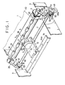
- a platen 5 is rotatably supported between a pair of frames 3 (only a right-hand one shown in Fig. 2).
- the platen 5 is coupled with a platen drive motor (not shown), such as a stepping motor or DC motor. As the drive motor is driven, the platen 5 rotates in a predetermined direction.
- a driving gear 7 is attached to the right-hand side (Fig. 1) of the platen 5.
- Each frame 3 is formed with a bearing slot 3a (Fig. 2), as bearing means, elongated in the transverse direction of the printer 1 or in the longitudinal direction of the frame 3.
- a guide shaft 11 is supported by the respective bearing slots 3a of the frames 3, so as to be rotatable parallel to the axis of the platen 5 and movable in the transverse direction perpendicular to an axis X-X (Fig. 2).
- the guide shaft 11 is located relatively to the bearing slots 3a by eccentric cam members 41, fixed pins 53, and leaf springs 40, which will be described in detail later.
- a carriage 13 is fitted on the guide shaft 11 so as to be slidable along the axis X-X of the shaft 11.
- the print head 15 prints on a printing medium 10, such as printing paper, on the platen 5, using print data in the form of a dot-matrix.
- a number of electromagnets, contained in the head 15, are driven selectively in accordance with the print data, so that print wires corresponding to the electromagnets are operated.
- the print head 15 itself has a conventional construction.
- a paper-thickness sensor 17 is mounted on the carriage 13 by means of a bracket 18. As shown in Fig. 3, a block 19 is fixed to the platen-side face of an upright portion of the bracket 18. An adjust screw 20 is screwed in the upright portion of the bracket 18, so as to penetrate the block 19. A sensing element 23 is attached to the tip end the adjust screw 20.
- the sensing element 23 includes a sensor body 21 and a pair of electrodes 22a and 22b, between which the body 21 is sandwiched.
- the sensor body 21 is formed of pressure- sensitive conductive rubber, whose electric resistance varies gradually, depending on external pressure.
- a cap cover 24 is attached to the block 19 so as to cover the sensing element 23.
- An opening 24a is formed in the front end face of the cover 24 so that the sensing element 23 can be exposed toward the platen 5.
- a leaf spring 25 is fixedly held between the block 19 and the bottom portion of the basal end of the cover 24.
- a distal bent portion 25a of the leaf spring 25 is fitted on the outside electrode 22a.
- the outer surface of the bent portion 25a projects slightly from the opening 24a toward the platen 5, so as to be located between the platen 5 and the printing surface of the print head 15.
- the distance between the bent portion 25a and the surface of the printing paper 10 on the platen 5 is narrower than that between the printing surface of the head 15 and paper surface.
- a pair of paper bail arms 29 are supported individually on the paired frames 3, so as to be rockable around their corresponding shaft pins 31, fixed to the frames 3.
- a paper bail shaft 33 is rotatably mounted on the respective free ends of the paper bail arms 29.
- a number of bail rollers 35 are fitted on the shaft 33, at predetermined intervals in the axial direction of the shaft 33.
- the paper bail arm 29, shaft 33, and bail rollers 35 constitute medium holding means for holding the printing medium 10 down on the platen 5.
- a driven gear 37 is mounted on the right end portion of the shaft 33, so as to be in mesh with the driving gear 7.
- a tension spring 39 as an urging member, is anchored to an anchor hole 3b (Fig. 2) in each frame 3.
- the other end of the spring 39 is anchored to each corresponding paper bail arm 29.
- the tension springs 39 continually urge the paper bail arms 29 to rock toward the hold position, where the bail rollers 35 abut against the platen 5.
- Each of the leaf springs 40 is in sliding contact with the peripheral surface of each corresponding shaft end portion 11a of the guide shaft 11, which projects outward from its corresponding frame 3.
- the proximal end portion of the leaf spring 40 is fixed to the frame 3.
- the leaf springs 40 resiliently urge the guide shaft 11 to move back so that the print head 15 retracts from the platen 5.
- the eccentric cam members 41 and rotating members 43 are fixed to their corresponding shaft end portions 11a of the guide shaft 11. As seen from Fig. 2, the members 41 and 43 are fitted on each shaft end portion 11a in a nonrotatable manner, and are adapted to rotate together with the shaft 11.
- Each of the fixed pins 53, fixed to the frames 3, is in sliding contact with a cam surface 41a of each corresponding eccentric cam member 41, urged by the leaf spring 40.
- the guide shaft 11 moves in the transverse direction, that is, toward or away from the platen 5, depending on the gradual change of distance between the engaging point of the cam surface 41a and the rocking center of the cam member 41.
- the eccentric cam member 41 has an eccentricity E to an axis point A of the guide shaft 11.
- the distance between the point A and the engaging point of the cam surface 41a, in contact with the fixed pin 53 reduces gradually.
- the rotating member 43 on the right end portion (Fig. 1) of the guide shaft 11 is formed, on its periphery, with driving teeth 45 and a toothed sector portion 47, which constitutes part of operative-transmission means. That rotating member 43 on the left end portion is formed with a toothed sector portion 47 only.
- the driving teeth 45 of the right-hand rotating member 43 is coupled with the reversible stepping motor 49, by means of a motor shaft 49a and a driving gear 50 fixed thereon.
- the stepping motor 49 is fixed to right-hand frame 3. As the motor 49 is driven, the guide shaft 11 rotates in the clockwise or counterclockwise direction.
- the toothed sector portion 47 of each rotating member 43, on each end of the shaft 11 engages a toothed arm 51, which is formed on the proximal end portion of each paper bail arm 29.
- the toothed arms 51 constitute part of the operative-transmission means.
- a photocoupler (not shown), as position detecting means, is provided at a region corresponding to a release position of the paper bail arms 29. In response to a detection signal from the photocoupler, the drive of the stepping motor 49 is interrupted.
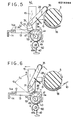
- Figs. 4 to 6 show different positions of the guide shaft 11 and the paper bail arm 29, which depend on the position of the eccentric cam member 41.
- Fig. 4 shows a nonoperative state before the printing paper is wound on the platen 5. In this state, the paper bail arm 29 is in the hold position where the rollers 35 are in contact with the platen 5.
- Numeral 55 designates a conventional paper guide plate, which serves to guide the printing paper, along the platen 5, from under the platen 5 to the print side where the print head 15 is located.
- the leading end of the printing paper 10, fed to the platen 5 is guided by the paper guide plate 55. Thereafter, the printing paper 10 passes freely between the printing surface of the print head 15 and the platen 5, spaced at a wide distance from each other, and is then fed upward to a predetermined paper-feed position, between the rollers 35 in the release position and the platen 5.
- the platen drive motor is driven for a predetermined number of steps, after the leading end passes a paper detector (not shown), which is located near the printing position.
- the stepping motor 49 is driven reversely.
- the guide shaft 11, along with the eccentric cam member 41 and the rotating member 43 rotates in the counterclockwise direction, thereby returning the paper bail arm 29 from the release position to the hold position.
- the arm 29 presses the printing paper 10, in the predetermined position, against the platen 5, urged by the resilient force of the tension spring 39.
- the driving gear 7 engages the driven gear 37.
- the guide shaft 11 rotates in the counterclockwise direction, the distance between the center A of rotation of the eccentric cam member 41, and that portion of the cam surface 41a in sliding contact with the fixed pin 53, increases gradually. As a result, the guide shaft 11 is moved forward so that the print head 15 approaches the platen 5.
- the rollers 35 are first brought to the hold position. Then, in the range of the stroke S1, the toothed sector portion 47 is disengaged from the toothed arm 51, so that only the print head 15 is left in movement and approaches the platen 5.
- the outer surface of the distal bent portion 25a of the leaf spring 25 is pressed against the surface of the printing paper 10 on the platen 5.
- the electric resistance of the sensor body 21 lowers gradually.
- the drive of the stepping motor 49 is interrupted to stop the print head 15.
- the motor 49 is reversely rotated again so that a narrow gap is formed between the sensing end face of the sensor body 21 and the printing paper 10.
- the gap G between the printing surface of the print head 15 and the surface of the printing paper 10, on the platen 5 is adjusted so as to provide the desired printing pressure.
- the electromagnets in the printing head 15 are driven selectively in accordance with the print data, so that the print data is printed as a dot-matrix.
- the stepping motor 49 is driven in one direction, in setting the printing paper 10 in place in the printer 1.
- the print head 15 moves back or away from the platen 5, assisted by the cooperation of the rotating eccentric cam member 41 and the fixed pin 53, so that a gap, wide enough to permit a free passage of the printing paper 10, is formed between the printing surface of the print head 15 and the platen 5.
- the paper bail arms 29 are rocked from the hold position to the release position. In this manner, the leading end portion of the printing paper, transported with the rotation of the platen 5, is prevented positively from coming into contact with the print head 15.
- the printing paper can be fed securely.
- the driving gear 50, driven teeth 45, toothed sector portion 47, and toothed arm 51 have tooth configurations such that their engagement can be maintained if the rotating member 41 moves together with the guide shaft 11.
- the pressure setting gap G between the print head 15 and the platen 5 can be adjusted within the range of the stroke S1. In this range, the toothed sector portion 47 of the rotating member 41 and the toothed arm 51 are not in engagement, and the operation of the paper bail 29 is disabled, thus permitting a free gap adjustment for the setting of the printing pressure.
- the guide shaft 11 is moved together with the eccentric cam member 41, for the movement of the print head 15 transverse to the platen 5.
- the guide shaft may be allowed only to rotate so that the print head moves transversely with the rotation of the guide shaft, assisted by eccentric cam means disposed between the shaft and the carriage.
- operative-transmission means including the toothed sector portion 47 and the toothed arm 51, according to the above embodiment, may be replaced with levers which extend individually from the rotating member and the paper bail arm, and can engage each other.
Landscapes
- Common Mechanisms (AREA)
- Handling Of Sheets (AREA)
Applications Claiming Priority (2)
| Application Number | Priority Date | Filing Date | Title |
|---|---|---|---|
| JP214359/85 | 1985-09-26 | ||
| JP60214359A JPS6273978A (ja) | 1985-09-26 | 1985-09-26 | 印字装置 |
Publications (3)
| Publication Number | Publication Date |
|---|---|
| EP0216394A2 true EP0216394A2 (de) | 1987-04-01 |
| EP0216394A3 EP0216394A3 (en) | 1987-08-05 |
| EP0216394B1 EP0216394B1 (de) | 1989-08-30 |
Family
ID=16654475
Family Applications (1)
| Application Number | Title | Priority Date | Filing Date |
|---|---|---|---|
| EP86113300A Expired EP0216394B1 (de) | 1985-09-26 | 1986-09-26 | Papierzuführmechanismus für einen Drucker |
Country Status (4)
| Country | Link |
|---|---|
| US (1) | US4883375A (de) |
| EP (1) | EP0216394B1 (de) |
| JP (1) | JPS6273978A (de) |
| DE (1) | DE3665280D1 (de) |
Cited By (8)
| Publication number | Priority date | Publication date | Assignee | Title |
|---|---|---|---|---|
| EP0310002A2 (de) * | 1987-09-29 | 1989-04-05 | Sharp Kabushiki Kaisha | Betätigungsmechanismus für den Druckkopf eines Aufzeichnungsgerätes |
| FR2641229A1 (fr) * | 1988-12-29 | 1990-07-06 | Brother Ind Ltd | Dispositifs d'alimentation en papier pour appareils d'impression et mecanisme de relevage pour de tels dispositifs |
| US4941762A (en) * | 1988-01-28 | 1990-07-17 | Seiko Epson Corporation | Switching mechanism for a paper holding roller of a printer |
| EP0388734A2 (de) * | 1989-03-10 | 1990-09-26 | Fujitsu Limited | Drucker mit einem Mechanismus zum Öffnen und Schliessen des Bügels |
| EP0435695A2 (de) * | 1989-12-29 | 1991-07-03 | Canon Kabushiki Kaisha | Tintenstrahlaufzeichnungsgerät |
| FR2665115A1 (fr) * | 1990-07-24 | 1992-01-31 | Seikosha Kk | Dispositif a barre presse-papier pour imprimante. |
| EP0472218A2 (de) * | 1990-08-24 | 1992-02-26 | Canon Kabushiki Kaisha | Aufzeichnungsgerät |
| CN1052191C (zh) * | 1990-07-20 | 2000-05-10 | 佳能株式会社 | 送纸机构及具有该机构的墨水喷射记录装置 |
Families Citing this family (22)
| Publication number | Priority date | Publication date | Assignee | Title |
|---|---|---|---|---|
| EP0292102B1 (de) * | 1987-03-24 | 1991-07-17 | Fujitsu Limited | Papierstärkenregistriereinrichtung in einem Drucker |
| DE3830880A1 (de) * | 1988-09-08 | 1990-03-15 | Mannesmann Ag | Drucker, insbesondere matrixnadeldrucker, mit einer druckkopfabstandseinstelleinrichtung |
| JPH02111576A (ja) * | 1988-10-20 | 1990-04-24 | Seikosha Co Ltd | 紙押え機構 |
| IT1230273B (it) * | 1989-06-14 | 1991-10-18 | Bull Hn Information Syst | Azionatore automatico di dispositivo premicarta per stampante. |
| US5087141A (en) * | 1989-12-19 | 1992-02-11 | Hewlett-Packard Company | Combination pinch roller and carriage guide for printer |
| SE465666B (sv) * | 1990-02-02 | 1991-10-14 | Philips Norden Ab | Apparat foer uppteckning och/eller avlaesning av information |
| SE465665B (sv) * | 1990-02-02 | 1991-10-14 | Philips Norden Ab | Apparat foer uppteckning och/eller avlaesning av information |
| GB2245867B (en) * | 1990-05-23 | 1993-12-15 | Seikosha Kk | Serial printer |
| EP0514155B1 (de) * | 1991-05-15 | 1995-08-09 | Seiko Epson Corporation | Serieller Anschlagdrucker |
| EP0577390B1 (de) * | 1992-06-30 | 2000-05-24 | Canon Kabushiki Kaisha | Tintenstrahlaufzeichnungsgerät |
| EP0645254A3 (de) * | 1993-09-24 | 1995-12-20 | Esselte Meto Int Gmbh | Druckmaschine mit Vorrichtung zum variieren der Andruckkraft des Druckkopfes auf die Druckwalze. |
| DE4332602C2 (de) * | 1993-09-24 | 1998-12-24 | Meto International Gmbh | Druckmaschine mit Druckwalze und Druckkopf |
| US5372443A (en) * | 1993-10-15 | 1994-12-13 | Brady Usa, Inc. | Adjustable platen for label printer |
| WO1996011111A1 (fr) * | 1994-10-06 | 1996-04-18 | Pfu Limited | Systeme et dispositif d'alimentation en papier pour imprimantes |
| JPH08187878A (ja) * | 1995-01-09 | 1996-07-23 | Brother Ind Ltd | インクジェット式印刷記録装置 |
| US5954440A (en) * | 1996-11-28 | 1999-09-21 | Agfa-Gevaert | Thermal printer with sheet pressure means |
| GB9702098D0 (en) * | 1997-01-31 | 1997-03-19 | Neopost Ltd | Thermal transfer printing apparatus |
| US5997199A (en) * | 1998-09-03 | 1999-12-07 | Mustek Systems Inc. | Paper feeding module of a color picture printer |
| US6398330B1 (en) * | 2000-01-04 | 2002-06-04 | Hewlett-Packard Company | Apparatus for controlling pen-to-print medium spacing |
| US6416146B1 (en) * | 2000-01-04 | 2002-07-09 | Hewlett-Packard Company | Apparatus for controlling pen-to-print medium spacing |
| JP4727292B2 (ja) * | 2005-05-12 | 2011-07-20 | 東芝テック株式会社 | サーマルプリンタ |
| JP4670466B2 (ja) * | 2005-05-12 | 2011-04-13 | セイコーエプソン株式会社 | プラテンギャップ調整装置及び印刷装置、並びに複合処理装置 |
Citations (3)
| Publication number | Priority date | Publication date | Assignee | Title |
|---|---|---|---|---|
| GB2008498A (en) * | 1977-11-22 | 1979-06-06 | Philips Nv | Printer comprising a printing head which is adjustable by means of a motor |
| US4420269A (en) * | 1981-03-27 | 1983-12-13 | Triumph-Adler A.G. Fur Buro- Und Informationstechnik | Device for lifting the printing head off the platen |
| EP0101841A2 (de) * | 1982-08-30 | 1984-03-07 | International Business Machines Corporation | Anordnung zum automatischen oder/und manuellen Öffnen eines Bügels |
Family Cites Families (21)
| Publication number | Priority date | Publication date | Assignee | Title |
|---|---|---|---|---|
| DE1561265A1 (de) * | 1966-06-10 | 1970-09-24 | Nippon Electric Co | Vorrichtung zum Einfuehren zusaetzlicher Schreibblaetter in eine Schreibmaschine |
| DE2358682A1 (de) * | 1973-11-24 | 1975-05-28 | Philips Patentverwaltung | Antriebsvorrichtung zur fortschaltung des sich bewegenden teiles einer druckvorrichtung |
| US4023662A (en) * | 1974-12-19 | 1977-05-17 | Ing. C. Olivetti & C., S.P.A. | Arrangement for adjusting the spacing between a print head and a platen |
| SE389061B (sv) * | 1975-03-06 | 1976-10-25 | Philips Svenska Ab | Tryckhuvud med distansorgan for instellning av tryckavstand |
| US4024940A (en) * | 1976-04-13 | 1977-05-24 | Mannesmann Aktiengesellschaft | Matrix printer having document thickness compensating device |
| JPS5541228A (en) * | 1978-09-18 | 1980-03-24 | Ricoh Co Ltd | Method of wear detection for recording stylus |
| DE3008540C2 (de) * | 1980-03-06 | 1982-07-22 | Triumph-Adler Aktiengesellschaft für Büro- und Informationstechnik, 8500 Nürnberg | Vorrichtung an Schreibwalzenlagergestell von Schreib- oder ähnlichen Maschinen zum Verstellen der Schreibwalze in Abdruckrichtung |
| DE3014823C2 (de) * | 1980-04-15 | 1986-10-09 | Mannesmann AG, 4000 Düsseldorf | Matrixdrucker mit einem zur Druckspalteinstellung anstellbaren Druckkopf |
| JPS5749587A (en) * | 1980-09-11 | 1982-03-23 | Tokyo Electric Co Ltd | Printer |
| JPS5756284A (en) * | 1980-09-19 | 1982-04-03 | Oki Electric Ind Co Ltd | Printer |
| EP0063588B1 (de) * | 1980-11-04 | 1986-04-09 | Wang Laboratories Inc. | Durch die obere papierandruckschiene gesteuerte papierzuführ- und -fördereinrichtung |
| JPS57170779A (en) * | 1981-04-15 | 1982-10-21 | Fujitsu Ltd | Hammer driving system for printer |
| SU1014770A1 (ru) * | 1981-08-14 | 1983-04-30 | Предприятие П/Я А-1397 | Исполнительный механизм термопечатающего устройства |
| JPS6079981A (ja) * | 1983-10-07 | 1985-05-07 | Fuji Xerox Co Ltd | 転写型感熱記録装置 |
| JPS60104363A (ja) * | 1983-11-11 | 1985-06-08 | Matsushita Electric Ind Co Ltd | タイプライタ |
| JPS60116487A (ja) * | 1983-11-30 | 1985-06-22 | Nec Home Electronics Ltd | プリンタの紙送り装置 |
| FR2557909B1 (fr) * | 1984-01-06 | 1988-08-12 | Dalo Jean | Abri leger en forme de tente. |
| JPS59209166A (ja) * | 1984-04-13 | 1984-11-27 | Matsushita Electric Ind Co Ltd | 印字装置 |
| US4676675A (en) * | 1984-05-09 | 1987-06-30 | Brother Kogyo Kabushiki Kaisha | Media thickness compensating device for a printer |
| JPS61154869A (ja) * | 1984-12-27 | 1986-07-14 | Seikosha Co Ltd | 印字ヘツドの位置調整機構 |
| JPS61167589A (ja) * | 1985-01-18 | 1986-07-29 | Olympus Optical Co Ltd | インクジエツトプリンタ |
-
1985
- 1985-09-26 JP JP60214359A patent/JPS6273978A/ja active Pending
-
1986
- 1986-09-26 DE DE8686113300T patent/DE3665280D1/de not_active Expired
- 1986-09-26 EP EP86113300A patent/EP0216394B1/de not_active Expired
-
1989
- 1989-04-12 US US07/338,390 patent/US4883375A/en not_active Expired - Lifetime
Patent Citations (3)
| Publication number | Priority date | Publication date | Assignee | Title |
|---|---|---|---|---|
| GB2008498A (en) * | 1977-11-22 | 1979-06-06 | Philips Nv | Printer comprising a printing head which is adjustable by means of a motor |
| US4420269A (en) * | 1981-03-27 | 1983-12-13 | Triumph-Adler A.G. Fur Buro- Und Informationstechnik | Device for lifting the printing head off the platen |
| EP0101841A2 (de) * | 1982-08-30 | 1984-03-07 | International Business Machines Corporation | Anordnung zum automatischen oder/und manuellen Öffnen eines Bügels |
Cited By (17)
| Publication number | Priority date | Publication date | Assignee | Title |
|---|---|---|---|---|
| US5071266A (en) * | 1987-09-29 | 1991-12-10 | Sharp Kabushiki Kaisha | Head engagement mechanism for thermal recording apparatus |
| EP0310002A3 (en) * | 1987-09-29 | 1989-10-18 | Sharp Kabushiki Kaisha | Head driving mechanism for recording apparatus |
| EP0310002A2 (de) * | 1987-09-29 | 1989-04-05 | Sharp Kabushiki Kaisha | Betätigungsmechanismus für den Druckkopf eines Aufzeichnungsgerätes |
| US4941762A (en) * | 1988-01-28 | 1990-07-17 | Seiko Epson Corporation | Switching mechanism for a paper holding roller of a printer |
| FR2641229A1 (fr) * | 1988-12-29 | 1990-07-06 | Brother Ind Ltd | Dispositifs d'alimentation en papier pour appareils d'impression et mecanisme de relevage pour de tels dispositifs |
| US5071275A (en) * | 1989-03-10 | 1991-12-10 | Fujitsu Limited | Printer having a bail roller opening and closing mechanism |
| EP0388734A3 (de) * | 1989-03-10 | 1991-04-24 | Fujitsu Limited | Drucker mit einem Mechanismus zum Öffnen und Schliessen des Bügels |
| EP0388734A2 (de) * | 1989-03-10 | 1990-09-26 | Fujitsu Limited | Drucker mit einem Mechanismus zum Öffnen und Schliessen des Bügels |
| US5120146A (en) * | 1989-03-10 | 1992-06-09 | Fujitsu Limited | Printer having a bail roller opening and closing mechanism |
| EP0435695A2 (de) * | 1989-12-29 | 1991-07-03 | Canon Kabushiki Kaisha | Tintenstrahlaufzeichnungsgerät |
| EP0435695A3 (en) * | 1989-12-29 | 1991-12-18 | Canon Kabushiki Kaisha | Ink jet recording apparatus |
| US5610636A (en) * | 1989-12-29 | 1997-03-11 | Canon Kabushiki Kaisha | Gap adjusting method and ink jet recording apparatus having gap adjusting mechanism |
| CN1052191C (zh) * | 1990-07-20 | 2000-05-10 | 佳能株式会社 | 送纸机构及具有该机构的墨水喷射记录装置 |
| FR2665115A1 (fr) * | 1990-07-24 | 1992-01-31 | Seikosha Kk | Dispositif a barre presse-papier pour imprimante. |
| EP0472218A2 (de) * | 1990-08-24 | 1992-02-26 | Canon Kabushiki Kaisha | Aufzeichnungsgerät |
| EP0472218A3 (en) * | 1990-08-24 | 1992-06-03 | Canon Kabushiki Kaisha | Recording apparatus |
| US5673074A (en) * | 1990-08-24 | 1997-09-30 | Canon Kabushiki Kaisha | Recording apparatus having urging member to prevent floating of recording sheet |
Also Published As
| Publication number | Publication date |
|---|---|
| EP0216394B1 (de) | 1989-08-30 |
| EP0216394A3 (en) | 1987-08-05 |
| DE3665280D1 (en) | 1989-10-05 |
| US4883375A (en) | 1989-11-28 |
| JPS6273978A (ja) | 1987-04-04 |
Similar Documents
| Publication | Publication Date | Title |
|---|---|---|
| US4883375A (en) | Printing device | |
| US4373824A (en) | Ribbon tension and metering control | |
| JP3223037B2 (ja) | サーマルプリンタ装置 | |
| JP2782728B2 (ja) | プリンタの紙送り装置 | |
| US5156467A (en) | Printer with media thickness adjustment of platen | |
| US4860028A (en) | Print head assembly | |
| US4702629A (en) | Apparatus for adjusting the print head gap in a dot matrix printer | |
| US4210076A (en) | Printing apparatus | |
| JPH04135769A (ja) | ピンチローラとキャリッジガイドを組み合わせてなるプリンタ | |
| US4780007A (en) | Record media thickness compensating mechanism | |
| US4859099A (en) | Automatic paper loading apparatus for printer having paper bail actuating device | |
| JPH0441655B2 (de) | ||
| JPH0632958B2 (ja) | ヘツドギヤツプ自動調整機構 | |
| JPH0131497Y2 (de) | ||
| JP3600273B2 (ja) | シート導入装置 | |
| JPH11334154A (ja) | テープ/チューブプリンタ | |
| US5244289A (en) | Printer having device for adjusting print hammer stroke | |
| JPS6334033B2 (de) | ||
| JPH06238967A (ja) | 通帳類印字装置 | |
| KR900004743Y1 (ko) | 프린터의 인쇄거리 자동 조절장치 | |
| JP2543726Y2 (ja) | 印字ヘッドの接離駆動機構 | |
| JP2789344B2 (ja) | 液体噴射記録装置 | |
| EP0314598A2 (de) | Betätigungsmechanismus für Thermo-Druckkopf | |
| JPH0369381A (ja) | サーマルヘッド押圧装置 | |
| JPS6132776Y2 (de) |
Legal Events
| Date | Code | Title | Description |
|---|---|---|---|
| PUAI | Public reference made under article 153(3) epc to a published international application that has entered the european phase |
Free format text: ORIGINAL CODE: 0009012 |
|
| AK | Designated contracting states |
Kind code of ref document: A2 Designated state(s): DE FR GB IT |
|
| PUAL | Search report despatched |
Free format text: ORIGINAL CODE: 0009013 |
|
| RHK1 | Main classification (correction) |
Ipc: B41J 25/28 |
|
| AK | Designated contracting states |
Kind code of ref document: A3 Designated state(s): DE FR GB IT |
|
| 17P | Request for examination filed |
Effective date: 19870902 |
|
| 17Q | First examination report despatched |
Effective date: 19881104 |
|
| GRAA | (expected) grant |
Free format text: ORIGINAL CODE: 0009210 |
|
| AK | Designated contracting states |
Kind code of ref document: B1 Designated state(s): DE FR GB IT |
|
| REF | Corresponds to: |
Ref document number: 3665280 Country of ref document: DE Date of ref document: 19891005 |
|
| ET | Fr: translation filed | ||
| ITF | It: translation for a ep patent filed | ||
| PLBE | No opposition filed within time limit |
Free format text: ORIGINAL CODE: 0009261 |
|
| STAA | Information on the status of an ep patent application or granted ep patent |
Free format text: STATUS: NO OPPOSITION FILED WITHIN TIME LIMIT |
|
| 26N | No opposition filed | ||
| ITTA | It: last paid annual fee | ||
| PGFP | Annual fee paid to national office [announced via postgrant information from national office to epo] |
Ref country code: FR Payment date: 19920909 Year of fee payment: 7 |
|
| PGFP | Annual fee paid to national office [announced via postgrant information from national office to epo] |
Ref country code: GB Payment date: 19930916 Year of fee payment: 8 |
|
| PGFP | Annual fee paid to national office [announced via postgrant information from national office to epo] |
Ref country code: DE Payment date: 19930922 Year of fee payment: 8 |
|
| PG25 | Lapsed in a contracting state [announced via postgrant information from national office to epo] |
Ref country code: FR Free format text: LAPSE BECAUSE OF NON-PAYMENT OF DUE FEES Effective date: 19940531 |
|
| REG | Reference to a national code |
Ref country code: FR Ref legal event code: ST |
|
| PG25 | Lapsed in a contracting state [announced via postgrant information from national office to epo] |
Ref country code: GB Effective date: 19940926 |
|
| GBPC | Gb: european patent ceased through non-payment of renewal fee |
Effective date: 19940926 |
|
| PG25 | Lapsed in a contracting state [announced via postgrant information from national office to epo] |
Ref country code: DE Effective date: 19950601 |
|
| PG25 | Lapsed in a contracting state [announced via postgrant information from national office to epo] |
Ref country code: IT Free format text: LAPSE BECAUSE OF NON-PAYMENT OF DUE FEES;WARNING: LAPSES OF ITALIAN PATENTS WITH EFFECTIVE DATE BEFORE 2007 MAY HAVE OCCURRED AT ANY TIME BEFORE 2007. THE CORRECT EFFECTIVE DATE MAY BE DIFFERENT FROM THE ONE RECORDED. Effective date: 20050926 |