EP0216096B1 - Dispositif pour la coupure par le central d'un poste branché involontairement sur la ligne dans une connexion à deux postes pouvant être branchés alternativement sur la ligne de façon automatique - Google Patents
Dispositif pour la coupure par le central d'un poste branché involontairement sur la ligne dans une connexion à deux postes pouvant être branchés alternativement sur la ligne de façon automatique Download PDFInfo
- Publication number
- EP0216096B1 EP0216096B1 EP86110895A EP86110895A EP0216096B1 EP 0216096 B1 EP0216096 B1 EP 0216096B1 EP 86110895 A EP86110895 A EP 86110895A EP 86110895 A EP86110895 A EP 86110895A EP 0216096 B1 EP0216096 B1 EP 0216096B1
- Authority
- EP
- European Patent Office
- Prior art keywords
- telephone line
- switching device
- line
- over
- telephone
- Prior art date
- Legal status (The legal status is an assumption and is not a legal conclusion. Google has not performed a legal analysis and makes no representation as to the accuracy of the status listed.)
- Expired - Lifetime
Links
Images

Classifications
-
- H—ELECTRICITY
- H04—ELECTRIC COMMUNICATION TECHNIQUE
- H04M—TELEPHONIC COMMUNICATION
- H04M1/00—Substation equipment, e.g. for use by subscribers
- H04M1/71—Substation extension arrangements
- H04M1/715—Substation extension arrangements using two or more extensions per line
Definitions
- the invention relates to a device on a telephone subscriber line with two alternately automatically connectable speech units for switching off a speech station having an unwanted loop closure from the switching center, with the features from the preamble of patent claim 1.
- control signals emitted by the switching center to trigger the test can be DC voltage signals on the one hand and AC voltage signals of specified voltage and frequency on the other hand.
- the test can also be triggered if there is a short-circuit closing the loop in the telephone set of the subscriber line.
- the AC voltage signals are picked up by means of a transformer connected in series in a telephone wire.
- An interface using a transmitter is also disclosed in FR-A-2 492 206.
- the object underlying the invention was to modify the older device cited at the outset in such a way that when a short circuit occurs in one of the two microphone units, this microphone unit is automatically switched off without intervention from the switching center, whereas if there is an unwanted loop closure, for example if one forgot to put the receiver on the fork, the microphone unit can be switched off from the switching center as part of a test cycle.
- the intercom should be automatically reset to the state without access from the control center, in which it can be connected to the telephone line via the changeover switching device.
- the acceptance of the AC voltage signals to trigger the test cycle should be possible in such a way that no transformers or other inductive components have to be switched into the line.
- the DC voltage prevailing on the telephone line is monitored by the device according to the invention, it being possible to distinguish whether there is a short circuit or only an unwanted loop closure due to the receiver not being hung up in one of the two microphone stations when the voltage drops got to.
- the defective intercom station is immediately automatically disconnected from the two-way switching device, in such a way that both shutdown devices between the two-way switching device and a set signal is supplied to each of the intercom stations, so that both intercom stations are disconnected first and when the monitoring device becomes effective at both intercom stations it is determined in which of the two intercom stations there is no short circuit and this intercom station is immediately automatically reconnected to the two-way switching device. Calls can then be made from this call station immediately, while the defective call station remains switched off until the short circuit has been remedied.
- this loop closure is ascertained when the telephone line is checked by the switching center. In this case, too, a set signal is fed to both shutdown devices, so that both microphone units are disconnected from the two-way switching device. In this case, the monitoring device determines after the end of the test cycle in which of the two call stations the loop is interrupted and switches this call station back to the change-over switching device, while the other call station remains disconnected until the unwanted loop closure is eliminated.
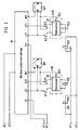
- a telephone line a0, b0 coming from an exchange, not shown, is connected via switching contacts s to a further section of the telephone line a1, b1, which leads to a two-way switching device W, to the two microphone units Sp1 and Sp2 of the subscriber line are connected, which can be alternately connected to the telephone line a1, b1 via the changeover switching device W.
- circuit parts arranged in the known changeover switching device which essentially consist of bistable relay circuits and loop current detection circuits, are not shown and are not described in more detail below.
- the output a11 is connected to the wire a1 and the output B1 is connected to the wire b1 of the telephone line, and the output b21 is separated from the wire b1.
- the output a21 is connected to the wire a1 and the output B2 is connected to the wire b1 of the telephone line and the output b11 is separated from the wire b1.
- a device for testing the telephone line from the switching center which has a switchover device U and a test device P, is arranged in front of the changeover switching device W, as shown in FIG. 1.
- the switchover device U can be controlled on the one hand by a DC voltage control signal, for example an increase in the line voltage to 100 V, and on the other hand by an AC voltage signal.
- the switching device U contains a DC voltage control switch 2 which is connected to the two branches a1, b1 of the telephone line and which responds to an increase in the line voltage.
- This DC voltage control switch 2 can also be constructed in a manner known per se so that it responds to a brief reversal of the polarity of the DC line voltage.
- the control input of a control switch 9 is connected to the branch a0, b0 of the telephone line coming from the exchange in parallel connection via an active filter 3 and a switching amplifier 5.
- the output of the control switch 9 is connected to a first winding S1 of a bistable relay, the switch contacts s of which are arranged in the telephone line a0, b0, viewed from the switching center, in front of the connection point of the DC voltage control switch.
- the input of the control switch 9 and the feed inputs of the switching amplifier 5 and the active filter 3 can be connected to the telephone line a0, b0 via a controllable switching device 18.
- the DC voltage control switch 2 is also connected to the first winding S1 via the control switch 9.
- the subscriber connection can be connected again to the telephone line a0, b0 via the contacts s.
- the test device P contains a device 7 connected via a rectifier bridge 6 arranged for protection against line reversals and a current stabilizer 1 for generating the supply voltages necessary for the test device. Furthermore, it contains a low-frequency generator 8, the output signals can be fed via a capacitor C1 to the telephone line a0, b0. In a manner not shown, the low-frequency generator can emit signals with fixed, predetermined frequencies or be swept over a certain frequency range.
- the test device P shown in Fig. 1 further comprises a first monitoring device P1, which continuously determines whether the DC voltage prevailing on the telephone line when the subscriber line is connected is, for example as a result of an unwanted loop closure, below a predetermined maximum value, but still above the minimum value signaling a short circuit.
- a first voltage sensor 17 is connected via a rectifier bridge 10 to the telephone line a0, b0 in front of the switch contacts s.
- the output of the first voltage sensor 17 is connected to the control input of the controllable switching device 18, by means of which the input of the control switch 9 can be connected to the telephone line in terms of direct voltage.
- Another controllable switching device 19 connects the device 7 for generating the supply voltages to a line e1, which leads to the shutdown devices K11 and K21 described below.
- a capacitor C20 ensures that the switching device 19 switches itself on with a delay when a voltage signal is present.
- the test device P further comprises a second monitoring device P2, which continuously determines whether the DC voltage on the telephone line a0, b0 drops to a value below a predetermined minimum value as a result of a short circuit in the subscriber station.
- a second voltage sensor 11 is connected to the telephone line a0, b0 in front of the switch contacts s, the output of which is connected to the control input of a controllable switching device 12, the input of which is connected to a storage capacitor C13, which is also constantly connected to the telephone line a0 via a diode D14 , b0 is connected.
- the output of the controllable switching device 12 is in turn connected to the line e1 leading to the switch-off device K11, K21.
- switch-off devices K11 and K21 are arranged between the two-way switching device W and the two intercom stations Sp1 and Sp2, by means of which a resettable disconnection of the intercom stations Sp1 and Sp2 from the two-way switching device W is possible.
- the shutdown device assigned to the intercom Sp1 is a bistable relay with a set winding K11 and a reset winding K12.
- the switch contacts k1 of this relay are arranged so that they connect the output b11 of the changeover switching device W to the intercom Sp1 in the non-set state.
- the set winding K11 is connected to the line e1 via a set input e11.
- a monitoring circuit 16 which is explained in more detail below and which contains the reset winding K12, is on the one hand permanently connected to the call station Sp1 via a reset input RS1 and a line b10 and can be connected to the outputs a11, b11 of the changeover switching device W via the switch contacts k1.
- the switch-off device assigned to the conference unit Sp2 is a bistable relay with a set winding K21 and a reset winding K22 and switch contacts k2, via which the output b21 is connected to the conference unit Sp2 in the non-set state.
- the monitoring device 26 has the reset winding K22 and is connected to the call station Sp2 via the reset input RS2 and can be connected to the outputs a21 and b21 of the changeover switching device W via the switch contacts k2.
- the set winding K21 is connected to the line e1 via the set input e21.
- the output B1 of the changeover switching device W is connected to the test device P via a line d1 in the manner shown in FIG. 1, while in an analogous manner the output B2 is also connected to the test device P via the line c1.
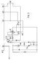
- FIG. 3 serves to explain the structure of the monitoring device 26 in more detail.
- the monitoring device 16 is constructed analogously.
- the reset winding K22 of the bistable relay is located in the monitoring device 26 in a circuit which is connected from a rectifier bridge 24 connected via the switching contacts k2 to the outputs a21 and b21 of the changeover switching device W via a transistor Tr23, the relay winding K22 and a thyristor Th2 runs back to the rectifier bridge 24.
- this circuit runs a control circuit which is connected from the reset input RS2 to the base of the transistor Tr23.
- the second voltage sensor 11 detects that the voltage on the telephone line a0, b0 has dropped to a value below a predetermined minimum value, for example to a value below 2V. It emits a control signal by means of which the switching device 12 is switched through and the line e1 is connected to the storage capacitor C13 which still has a stored voltage value. The result of this is that a set signal is fed to the set inputs e11 and e21 via the line e1 and the set windings K11 and K21 are thereby activated, as a result of which the contacts k1 and k2 are flipped over and thus both microphone units Sp1 and Sp2 are separated from the changeover switching device W.
- the transistor Tr23 remains blocked because, as a result of the short circuit in the call station Sp2, the base of the transistor Tr23 is connected via this short circuit to the output a21 of the changeover switching device W, which carries negative voltage. No current flows through the reset winding K22.
- the transistor Tr23 switches through, the reset winding K22 is activated and the intercom station Sp2 is again connected to the changeover switching device W.
- this microphone unit Sp2 is constantly connected to the telephone line a1, b1 due to the mode of operation of the changeover switching device W, while the microphone unit Sp1 is disconnected and no calls can be made from it.
- the facility for checking the telephone line must be activated. This usually happens - that is, if there is no loop closure in the subscriber station - by one from the exchange Voltage increase on the telephone line, for example from 60 V to 100 V.
- This DC voltage control signal activates the DC voltage control switch 2 in the switching device U and thus excites the relay winding S1 via the control switch 9 and switches the relay contacts s.
- the first voltage sensor 17 detects that the voltage on the telephone line a0, b0 is reduced and is, for example, in a range between 13V and 6V. In this case, the voltage sensor 17 emits a control signal by means of which the controllable switching device 18 is switched through.
- an AC voltage control signal is emitted at a frequency of, for example, 800 Hz.
- This AC voltage signal runs through the active filter 3 to the switching amplifier 5, the switching pulse of which is fed to the control input of the control switch 9, as a result of which it is switched through and the relay winding S1 is activated.
- the test device P When the relay contacts s are switched over, the test device P is connected to the telephone line a0, b0, so that the loop is no longer effective and the full DC voltage is again present on the telephone line.
- the device 7 for generating the supply voltages which receives its supply voltage from the telephone line, is switched on. When the device 7 is activated, all the individual devices of the test device P are switched on. In particular, a DC voltage control signal is given via line e2 to wire b1 to changeover switching device W.
- the output B2 is connected to the wire b1, so that the direct voltage control signal runs back to the test device P via the line c1 and controls the low-frequency generator 8 there so that a signal of a certain frequency is generated and given into the telephone line a0, b0, so that it can be recognized in the exchange that the disturbance in the call station Sp2 is to be found.
- a DC voltage signal is simultaneously sent to the controllable switching device 19, which switches through and thus gives a set signal via the line e1 to both shutdown devices K11 and K21. Both switching stations are separated from the changeover switching device W via the switch contacts k1 and k2.
- test device P After the defective call station has been disconnected, further test cycles can be carried out using the test device P.
- the low-frequency generator 8 is swept over a frequency range of 300 to 3400 Hz, for example, in order to check the frequency response of the telephone line.
- the relay winding S2 is activated from the time switch 4 and the changeover switching device W is reconnected to the telephone line a0, b0 via the contacts s.
- the monitoring device 16 determines that there is no loop closure in the station Sp1 and activates the reset winding K12. As a result, the microphone unit Sp1 is reconnected.
- the monitoring device 26 determines that there is a loop closure and the intercom Sp2 remains disconnected until the loop closure is resolved.
- a normal call can then be made again from the intact call station, while the call station at which the receiver was not on-hook remains disconnected until the receiver is replaced, which is recognized by the corresponding monitoring device 26 or 16 and for switching on again leads this station to the changeover switching device W.
Landscapes
- Engineering & Computer Science (AREA)
- Signal Processing (AREA)
- Interconnected Communication Systems, Intercoms, And Interphones (AREA)
- Sub-Exchange Stations And Push- Button Telephones (AREA)
- Monitoring And Testing Of Exchanges (AREA)
Claims (4)
- Dispositif pour un raccordement d'abonné téléphonique, avec deux postes pouvant être branchés alternativement sur la ligne de façon automatique (Sp1, Sp2,) pour la coupure d'un poste présentant une fermeture de boucle involontaire par le central de communication , avec un dispositif de commutation alternée (W) disposé entre le commutateur téléphonique (a1, b1) et les postes au moyen duquel, en cas de fermeture de la boucle dans l'un des deux postes, ce poste est raccordé au conducteur téléphonique et l'autre poste est coupé, et avec un dispositif pour vérifier le conducteur téléphonique entre le central de communication et le raccordement d'abonné depuis le central de communication , qui présente un dispositif de commutation (U-51-52-S) pouvant être raccordé par un signal de commande émis par le central de communication et raccordé immédiatement avant le raccordement d'abonné au conducteur téléphonique pour couper le raccordement d'abonné du conducteur téléphonique et pour raccorder un dispositif de vérification (P) au conducteur téléphonique tandis que, dans le dispositif de vérification, est raccordé un dispositif pour produire des tensions d'alimentation (7) et que, par le dispositif de vérification, des signaux de vérification de fréquence prédéterminée sont envoyés dans le conducteur téléphonique et que, après l'achèvement du cycle de vérification, un signal de désactivation est envoyé au dispositif de commutation pour ré-enclencher le raccordement d'abonné au conducteur téléphonique et dans lequel est disposé, entre le dispositif de commutation alternée et les deux postes, un dispositif de déclenchement (K1, K2) pour couper le poste concerné du dispositif de commutation alternée qui présente un élément de commutation réglable bi-stable disposé dans le conducteur de liaison entre le poste et le dispositif de commutation alternée, avec une entrée d'activation et une entrée de désactivation, tandis que l'entrée d'activation est connectée au dispositif de vérification qui émet un signal d'activation au début du cycle de vérification, et avec une entrée de désactivation raccordée à un dispositif de surveillance connecté à l'entrée du poste et qui émet un signal de désactivation dès qu'aucune fermeture de boucle n'existe dans un poste après sa coupure par rapport au dispositif de commutation alternée, caractérisé en ce que le dispositif de commutation (U-S1-S2-s) présente un commutateur de commande (9) réagissant à un signal de tension alternative de fréquence prédéterminée et connecté en permanence avec le conducteur téléphonique (a0, b0) en montage en parallèle et par lequel le dispositif de commutation (U-S1-S2-s) est commandé si un premier détecteur de tension (17), connecté au conducteur téléphonique (a0, b0) constate une valeur de tension qui est située entre une valeur maximale prédéterminée et une valeur minimale prédéterminée et par lequel est émis un signal de commande indiquant une fermeture de boucle involontaire tandis que, après activation du dispositif de commutation (U-S1-S2-s),les entrées d'activation (e11, e21) sont raccordées au dispositif (7) pour produire des tensions d'alimentation pour alimenter le signal d'activation et en ce qu'un dispositif (P2) existe pour constater un court-circuit au conducteur téléphonique, avec un deuxième détecteur de tension (11) et un condensateur d'accumulation (13) qui sont connectés tous deux en permanence au conducteur téléphonique (a0, b0) avant le dispositif de commutation (U-S1-S2-s), tandis que le condensateur d'accumulation (13) est connecté par un dispositif de commutation (12) pouvant être commandé par un deuxième détecteur de tension (11) aux entrées d'activation (e11, e21) dès que le deuxième détecteur de tension (11) constate une valeur de tension qui est située en dessous d'une valeur minimale prédéterminée et par lequel est produit un signal de commande indiquant un court-circuit.
- Dispositif selon la revendication 1, caractérisé en ce que le premier détecteur de tension (17) commande un dispositif de commutation (18) réglable par lequel l'entrée du commutateur de commande (9) est connectée en tension continue au conducteur téléphonqiue (a0, b0).
- Dispositif selon la revendication 1 ou 2, caractérisé en ce qu'on utilise comme éléments de commutation réglables des relais bi -stables dont les contacts de commutation (k1, k2) se trouvent dans le conducteur de liaison,entre le dispositif de commutation alternée (W) et les postes (Sp1, Sp2) dont les enroulements d'activation (K11, K21) sont raccordés chacun aux entrées d'activation (e11, e21) et dont les enroulements de désactivation (K12, K21) se trouvent chacun dans un circuit de commande qui est raccordé dans le cas de postes (Sp1, Sp2) séparé du dispositif de commutation en ce que,par une coupure de la boucle dans le poste, un circuit de courant (24-Pr23-K22-Th2-24) passant par l'enroulement de désactivation (K12, K22) est fermé.
- Dispositif selon l'une des revendications 1 à 3, caractérisé en ce que l'alimentation des tensions d'alimentation au dispositif (7) pour produire les tensions d'alimentation pour le dispositif de vérification (P) est effectuée par le conducteur téléphonique (a0,b0).
Priority Applications (1)
| Application Number | Priority Date | Filing Date | Title |
|---|---|---|---|
| AT86110895T ATE73283T1 (de) | 1985-09-16 | 1986-08-06 | Einrichtung an einem fernsprechteilnehmeranschluss mit zwei wechselweise automatisch anschaltbaren sprechstellen zur abschaltung einer, einen ungewollten schleifenschluss aufweisenden sprechstelle von der vermittlungsstelle aus. |
Applications Claiming Priority (2)
| Application Number | Priority Date | Filing Date | Title |
|---|---|---|---|
| DE3532960 | 1985-09-16 | ||
| DE3532960A DE3532960C1 (de) | 1985-09-16 | 1985-09-16 | Einrichtung an einem Fernsprech-Teilnehmeranschluss mit zwei wechselweise automatisch anschaltbaren Sprechstellen zur Abschaltung einer,einen ungewollten Schleifenschluss aufweisenden Sprechstelle von der Vermittlungsstelle aus |
Publications (3)
| Publication Number | Publication Date |
|---|---|
| EP0216096A2 EP0216096A2 (fr) | 1987-04-01 |
| EP0216096A3 EP0216096A3 (en) | 1989-03-22 |
| EP0216096B1 true EP0216096B1 (fr) | 1992-03-04 |
Family
ID=6281065
Family Applications (1)
| Application Number | Title | Priority Date | Filing Date |
|---|---|---|---|
| EP86110895A Expired - Lifetime EP0216096B1 (fr) | 1985-09-16 | 1986-08-06 | Dispositif pour la coupure par le central d'un poste branché involontairement sur la ligne dans une connexion à deux postes pouvant être branchés alternativement sur la ligne de façon automatique |
Country Status (3)
| Country | Link |
|---|---|
| EP (1) | EP0216096B1 (fr) |
| AT (1) | ATE73283T1 (fr) |
| DE (2) | DE3532960C1 (fr) |
Families Citing this family (1)
| Publication number | Priority date | Publication date | Assignee | Title |
|---|---|---|---|---|
| EP0700605B1 (fr) * | 1993-05-28 | 1998-08-05 | Siemens Aktiengesellschaft | Procede permettant de realiser un circuit equivalent pour un dispositif de transmission destine a la transmission bidirectionnelle de signaux numeriques et configuration de mise en oeuvre dudit procede |
Family Cites Families (5)
| Publication number | Priority date | Publication date | Assignee | Title |
|---|---|---|---|---|
| DE1054123B (de) * | 1957-08-01 | 1959-04-02 | Erhard Kuehnl | Schaltungsanordnung fuer Fernsprechanschluesse, insbesondere Zweieranschluesse |
| DE1933717A1 (de) * | 1969-07-03 | 1971-01-21 | Standard Elek K Lorenz Ag | Schaltungsanordnung fuer einen Zweieranschluss in Fernmelde-,insbesondere Fernsprechvermittlungsanlagen |
| US3843848A (en) * | 1973-01-12 | 1974-10-22 | Magnetic Controls Co | Telephone looptest system |
| IT1149225B (it) * | 1980-10-09 | 1986-12-03 | Italtel Spa | Disposizione circuitale per utenti duplex in centrali di commutazione telefonica di tipo elettronico |
| DE3513598A1 (de) * | 1985-04-16 | 1986-10-16 | Neumann Elektronik GmbH, 4330 Mülheim | Einrichtung zur pruefung einer fernmeldeleitung zwischen einer vermittlungsstelle und einem teilnehmeranschluss von der vermittlungsstelle aus |
-
1985
- 1985-09-16 DE DE3532960A patent/DE3532960C1/de not_active Expired
-
1986
- 1986-08-06 DE DE8686110895T patent/DE3684069D1/de not_active Expired - Fee Related
- 1986-08-06 EP EP86110895A patent/EP0216096B1/fr not_active Expired - Lifetime
- 1986-08-06 AT AT86110895T patent/ATE73283T1/de active
Also Published As
| Publication number | Publication date |
|---|---|
| ATE73283T1 (de) | 1992-03-15 |
| EP0216096A3 (en) | 1989-03-22 |
| DE3532960C1 (de) | 1987-02-05 |
| EP0216096A2 (fr) | 1987-04-01 |
| DE3684069D1 (de) | 1992-04-09 |
Similar Documents
| Publication | Publication Date | Title |
|---|---|---|
| EP0216096B1 (fr) | Dispositif pour la coupure par le central d'un poste branché involontairement sur la ligne dans une connexion à deux postes pouvant être branchés alternativement sur la ligne de façon automatique | |
| DE3628922C2 (fr) | ||
| DE2933439C2 (de) | Verfahren zur Inbetriebnahme der beidseitigen Fernspeisung von Zwischenstellen einer Einrichtung der Nachrichtenübertragungstechnik | |
| DE3633561C1 (en) | Change-over switching device for a telephone facility for connecting a number of extensions to a common telephone line | |
| EP0201734B1 (fr) | Equipement dans un terminal téléphonique pour abonnés pour la déconnexion d'une des deux sous-stations connectables alternativement et automatiquement par le central en cas d'une fermeture indésirée de boucle dans cette sous-station | |
| DE303642C (fr) | ||
| DE2811388A1 (de) | Schaltungsanordnung zur rufspannungszufuehrung in fernsprech-vermittlungsanlagen | |
| DE3609979C2 (fr) | ||
| DE2949513C2 (de) | Notrufanlage | |
| DE3633562C1 (en) | Change-over switching device for a telephone facility for connecting a number of extensions to a common telephone line | |
| DE19758273A1 (de) | Notspeisefähige Stromversorgung für ISDN-Endsysteme | |
| DE1901937C3 (de) | Schaltungsanordnung zur verstärkerfeidweisen Durchschaltung eines Vierdraht-Fernleitungsabschnittes zu Prüfzwecken | |
| DE3011758A1 (de) | Schaltungsanordnung fuer zwei parallelgeschaltete fernsprechapparate | |
| EP1110415B1 (fr) | Procede pour commuter un poste d'abonne d'un premier reseau de telecommunication sur un second reseau de telecommunication | |
| DE2754088A1 (de) | Schaltungsanordnung zum erkennen defekter ueberspannungsschutzmittel in fernsprechleitungen | |
| DE3502947A1 (de) | Schaltungsanordnung mit einer waehlsperre | |
| DE3400304A1 (de) | Schaltung zum erkennen eines schleifenzustands | |
| DE4340936C2 (de) | Schaltungsanordnung zur Ortung fehlerhafter ferngespeister Zwischenverstärker | |
| EP0226708A2 (fr) | Dispositifs électriques pour bloquer les appels sortants d'un poste téléphonique | |
| DE964684C (de) | Schaltungsanordnung fuer Fernsprechanlagen mit Relaiswaehlern und Verbindungsleitungen zu anderen AEmtern | |
| DE887220C (de) | Schaltungsanordnung fuer Fernsprechanlagen mit Gemeinschafts-anschluessen | |
| DE886765C (de) | Schaltungsanordnung fuer Fernsprechanlagen mit Haupt- und Unteraemtern | |
| DE4114702C1 (en) | Operating circuit for telephone party line - has respective call recognition units and identifies caller from direction of loop current | |
| DE874471C (de) | Schaltungsanordnung fuer Fernsprechanlagen mit Haupt- und Unteraemtern | |
| DE2512551C3 (de) | Schaltungsanordnung für Fernmeldevermittlungsanlagen, insbesondere Fernsprechvermittlungsanlagen mit Prüf- und Belegungsstromkreisen |
Legal Events
| Date | Code | Title | Description |
|---|---|---|---|
| PUAI | Public reference made under article 153(3) epc to a published international application that has entered the european phase |
Free format text: ORIGINAL CODE: 0009012 |
|
| AK | Designated contracting states |
Kind code of ref document: A2 Designated state(s): AT BE CH DE GB IT LI LU NL SE |
|
| PUAL | Search report despatched |
Free format text: ORIGINAL CODE: 0009013 |
|
| AK | Designated contracting states |
Kind code of ref document: A3 Designated state(s): AT BE CH DE GB IT LI LU NL SE |
|
| 17P | Request for examination filed |
Effective date: 19890410 |
|
| 17Q | First examination report despatched |
Effective date: 19910725 |
|
| GRAA | (expected) grant |
Free format text: ORIGINAL CODE: 0009210 |
|
| AK | Designated contracting states |
Kind code of ref document: B1 Designated state(s): AT BE CH DE GB IT LI LU NL SE |
|
| PG25 | Lapsed in a contracting state [announced via postgrant information from national office to epo] |
Ref country code: IT Free format text: LAPSE BECAUSE OF FAILURE TO SUBMIT A TRANSLATION OF THE DESCRIPTION OR TO PAY THE FEE WITHIN THE PRE;WARNING: LAPSES OF ITALIAN PATENTS WITH EFFECTIVE DATE BEFORE 2007 MAY HAVE OCCURRED AT ANY TIME BEFORE 2007. THE CORRECT EFFECTIVE DATE MAY BE DIFFERENT FROM THE ONE RECORDED.SCRIBED TIME-LIMIT Effective date: 19920304 Ref country code: NL Effective date: 19920304 Ref country code: SE Effective date: 19920304 |
|
| REF | Corresponds to: |
Ref document number: 73283 Country of ref document: AT Date of ref document: 19920315 Kind code of ref document: T |
|
| REF | Corresponds to: |
Ref document number: 3684069 Country of ref document: DE Date of ref document: 19920409 |
|
| GBT | Gb: translation of ep patent filed (gb section 77(6)(a)/1977) | ||
| NLV1 | Nl: lapsed or annulled due to failure to fulfill the requirements of art. 29p and 29m of the patents act | ||
| PLBE | No opposition filed within time limit |
Free format text: ORIGINAL CODE: 0009261 |
|
| STAA | Information on the status of an ep patent application or granted ep patent |
Free format text: STATUS: NO OPPOSITION FILED WITHIN TIME LIMIT |
|
| 26N | No opposition filed | ||
| PGFP | Annual fee paid to national office [announced via postgrant information from national office to epo] |
Ref country code: LU Payment date: 19930730 Year of fee payment: 8 |
|
| PGFP | Annual fee paid to national office [announced via postgrant information from national office to epo] |
Ref country code: GB Payment date: 19930804 Year of fee payment: 8 |
|
| EPTA | Lu: last paid annual fee | ||
| PGFP | Annual fee paid to national office [announced via postgrant information from national office to epo] |
Ref country code: BE Payment date: 19940607 Year of fee payment: 9 |
|
| PGFP | Annual fee paid to national office [announced via postgrant information from national office to epo] |
Ref country code: AT Payment date: 19940725 Year of fee payment: 9 |
|
| PGFP | Annual fee paid to national office [announced via postgrant information from national office to epo] |
Ref country code: CH Payment date: 19940805 Year of fee payment: 9 |
|
| PG25 | Lapsed in a contracting state [announced via postgrant information from national office to epo] |
Ref country code: GB Effective date: 19940806 Ref country code: LU Free format text: LAPSE BECAUSE OF NON-PAYMENT OF DUE FEES Effective date: 19940806 |
|
| GBPC | Gb: european patent ceased through non-payment of renewal fee |
Effective date: 19940806 |
|
| PG25 | Lapsed in a contracting state [announced via postgrant information from national office to epo] |
Ref country code: AT Effective date: 19950806 |
|
| PGFP | Annual fee paid to national office [announced via postgrant information from national office to epo] |
Ref country code: DE Payment date: 19950822 Year of fee payment: 10 |
|
| PG25 | Lapsed in a contracting state [announced via postgrant information from national office to epo] |
Ref country code: LI Effective date: 19950831 Ref country code: CH Effective date: 19950831 Ref country code: BE Effective date: 19950831 |
|
| BERE | Be: lapsed |
Owner name: NEUMANN ELEKTRONIK G.M.B.H. Effective date: 19950831 |
|
| REG | Reference to a national code |
Ref country code: CH Ref legal event code: PL |
|
| PG25 | Lapsed in a contracting state [announced via postgrant information from national office to epo] |
Ref country code: DE Effective date: 19970501 |