EP0215481B1 - Dispositif radar Doppler à impulsions et à traitement numérique de signaux - Google Patents
Dispositif radar Doppler à impulsions et à traitement numérique de signaux Download PDFInfo
- Publication number
- EP0215481B1 EP0215481B1 EP19860112867 EP86112867A EP0215481B1 EP 0215481 B1 EP0215481 B1 EP 0215481B1 EP 19860112867 EP19860112867 EP 19860112867 EP 86112867 A EP86112867 A EP 86112867A EP 0215481 B1 EP0215481 B1 EP 0215481B1
- Authority
- EP
- European Patent Office
- Prior art keywords
- processor
- bus
- processing
- preprocessor
- target
- Prior art date
- Legal status (The legal status is an assumption and is not a legal conclusion. Google has not performed a legal analysis and makes no representation as to the accuracy of the status listed.)
- Expired - Lifetime
Links
Images

Classifications
-
- G—PHYSICS
- G01—MEASURING; TESTING
- G01S—RADIO DIRECTION-FINDING; RADIO NAVIGATION; DETERMINING DISTANCE OR VELOCITY BY USE OF RADIO WAVES; LOCATING OR PRESENCE-DETECTING BY USE OF THE REFLECTION OR RERADIATION OF RADIO WAVES; ANALOGOUS ARRANGEMENTS USING OTHER WAVES
- G01S13/00—Systems using the reflection or reradiation of radio waves, e.g. radar systems; Analogous systems using reflection or reradiation of waves whose nature or wavelength is irrelevant or unspecified
- G01S13/02—Systems using reflection of radio waves, e.g. primary radar systems; Analogous systems
- G01S13/50—Systems of measurement based on relative movement of target
- G01S13/52—Discriminating between fixed and moving objects or between objects moving at different speeds
- G01S13/522—Discriminating between fixed and moving objects or between objects moving at different speeds using transmissions of interrupted pulse modulated waves
- G01S13/524—Discriminating between fixed and moving objects or between objects moving at different speeds using transmissions of interrupted pulse modulated waves based upon the phase or frequency shift resulting from movement of objects, with reference to the transmitted signals, e.g. coherent MTi
- G01S13/53—Discriminating between fixed and moving objects or between objects moving at different speeds using transmissions of interrupted pulse modulated waves based upon the phase or frequency shift resulting from movement of objects, with reference to the transmitted signals, e.g. coherent MTi performing filtering on a single spectral line and associated with one or more range gates with a phase detector or a frequency mixer to extract the Doppler information, e.g. pulse Doppler radar
-
- G—PHYSICS
- G01—MEASURING; TESTING
- G01S—RADIO DIRECTION-FINDING; RADIO NAVIGATION; DETERMINING DISTANCE OR VELOCITY BY USE OF RADIO WAVES; LOCATING OR PRESENCE-DETECTING BY USE OF THE REFLECTION OR RERADIATION OF RADIO WAVES; ANALOGOUS ARRANGEMENTS USING OTHER WAVES
- G01S13/00—Systems using the reflection or reradiation of radio waves, e.g. radar systems; Analogous systems using reflection or reradiation of waves whose nature or wavelength is irrelevant or unspecified
- G01S13/02—Systems using reflection of radio waves, e.g. primary radar systems; Analogous systems
- G01S13/50—Systems of measurement based on relative movement of target
- G01S13/52—Discriminating between fixed and moving objects or between objects moving at different speeds
- G01S13/522—Discriminating between fixed and moving objects or between objects moving at different speeds using transmissions of interrupted pulse modulated waves
- G01S13/524—Discriminating between fixed and moving objects or between objects moving at different speeds using transmissions of interrupted pulse modulated waves based upon the phase or frequency shift resulting from movement of objects, with reference to the transmitted signals, e.g. coherent MTi
- G01S13/5246—Discriminating between fixed and moving objects or between objects moving at different speeds using transmissions of interrupted pulse modulated waves based upon the phase or frequency shift resulting from movement of objects, with reference to the transmitted signals, e.g. coherent MTi post processors for coherent MTI discriminators, e.g. residue cancellers, CFAR after Doppler filters
Definitions
- the invention relates to a pulse Doppler radar device according to the preamble of claim 1.
- Such a pulse Doppler radar device is known from IEEE TRANSACTIONS ON AEROSPACE AND ELECTRONIC SYSTEMS, volume AES-15, No. 4, July 1979, pages 508-517, IEEE, New York, US; R: N. O'DONNEL et al .: "Automated tracking for aircraft surveillance radar systems" known.
- the moving target detector used here (moving target detector MTD) has a plurality of processor modules connected in parallel, and transmits the detected threshold violations as target messages to a so-called post processor.
- a double pulse suppression and a plurality of filters are implemented by the processor modules. The filters are used for Doppler processing and for performing algorithms for signal processing.
- the invention has for its object a flexible pulse Doppler evaluation adapted to the current conditions of natural and intentional interference signals, such as fixed sign echoes, rain echoes and active interferers and the detection of interest To improve targets that have a characteristic Doppler shift.
- the processor system for the postprocessing should not only enable universal use, but also a freely programmable radar signal evaluation.
- the universal usability also requires the ability to adapt the processing power and thus the effort to the respective application.
- the processor system provides the option of connecting a variable number of identical processors in parallel via different bus systems that can communicate with their environment.
- a decision is made according to certain criteria on the basis of which the transmitted spectra are analyzed, whether it is the echo of an object of interest or an interference signal. These criteria do not have to be unchangeable, but can usually be adapted to the current disturbance conditions.
- the control of the process and the setting of parameters for the transmitter, receiver and for preprocessing can be carried out by a separate process control or by the processor system itself.
- another bus is used as a connection to a memory device.
- a The task of this storage device is to correlate target messages in neighboring angular ranges and / or over one or more antenna revolutions.
- the multiprocessor system can be provided with a further bus which is connected to a further memory device and to which the signal preprocessing has access via the same bus or via its own bus.
- the preprocessing of the radar signals and the distance-selective pretreatment can be carried out by a separate multi-processor system.
- the tasks of radar signal evaluation can be divided into two areas, preprocessing and postprocessing.
- the task of preprocessing is in essentially the analysis of the echoes in the Doppler range with the help of a filter bank, which can be implemented as a real filter bank or as an FFT analysis, and the threshold control.
- the postprocessing task is first of all to eliminate false alarms as far as possible and to plot with sharpening in the angle and distance.
- further preprocessing depending on the particular application may be necessary in post-processing, such as Doppler sharpening, correlation with secondary radar measurement values, clutter adaptation, overreach elimination.
- a high processing speed is the primary requirement in preprocessing, since all data arising with the distance gate clock must be subjected to extensive processing.
- the parameters e.g. the number of coherently processed pulses, the type of weighting and, in the case of echo processing, a burst-wise or overlapping type can be selected.
- post-processing the input data rate is greatly reduced compared to preprocessing due to threshold formation, which simplifies further processing by processors. If the processing power of available processors is sufficient, both the preprocessing and the postprocessing can be carried out using processors.
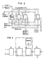
- the arrangement for preprocessing VV consists of a pre-filtering VF and a filter bank (or an FFT analyzer) FB. Preprocessing also includes a threshold control SST and a residual clutter card RCK.
- the preprocessing VV is followed by the postprocessing NV using a multi-processor system MPS with a raw target memory RSP and an associated sequence control AST.
- the digitized signals of the two quadrature channels I and Q supplied at the input of the prefiltering VF are supplied from quadrature detectors and analog / digital converters, not shown.
- the pre-filtering VF essentially serves to suppress single pulses.
- a filter for clutter suppression can be activated in areas with strong soil clutter.
- the received echoes are pretreated in a distance-selective manner by a filter device with at least one attenuation pole for the frequency zero before the Fourier transformation is carried out.
- a threshold for the current distance gate is formed for each Doppler channel by corresponding averaging over adjacent distance gates. If a threshold is exceeded in a Doppler channel, the spectrum in the current range gate (all Doppler channels), including the thresholds in the Doppler channels, is transferred to the subsequent postprocessing.
- the threshold control SST can optionally limit the number of target messages permitted in a block. This limitation is then carried out in such a way that the amount of data transferred to the postprocessing NV within a block is limited. Overloading of NV postprocessing is avoided even with intelligent interferers and the evaluated range is reduced in blocks.
- the sequence control AST continuously receives information about the current course of the evaluation from the postprocessing NV, so that the operating mode and the processing can be adjusted sector by sector.
- the threshold control SST there are several Different operating modes of the threshold control SST are possible.
- angle and distance-selective threshold increases of the individual Doppler channels can be carried out.
- individual Doppler channels can also be blocked for target messages in a manner that is selective in terms of angle and distance.
- the residual clutter card contains the information in which resolution cells there is no clutter and thus a target message is permissible even in the case of echoes that have not been shifted Doppler.
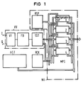
- the post-processing of the target messages is carried out by a multiprocessor system MPS from identical processor modules 1 to 4, which communicate with their environment via different bus systems. This includes at least one bus for data input from the upstream processing and one bus for forwarding the target messages.
- the multiprocessor system MPS is expanded by a so-called raw target memory RSP, to which all processors 1 to 4 have access via an additional bus.
- the raw target memory RSP serves on the one hand to correlate target messages in neighboring angular ranges and / or over one or more antenna revolutions. On the other hand, this raw target memory RSP is used to store the results of the individual processing steps and thus to communicate the individual processing steps.
- the MPS multiprocessor system it is decided according to certain criteria with which the transmitted spectra are analyzed whether it was the echo of an object of interest or an interference signal. These criteria do not have to be unchangeable and are usually adapted to the current disturbance conditions.
- the control of the process and the setting of parameters for the transmitter and receiver can be carried out by a separate process control AST or by the MPS multiprocessor system itself.
- the parallel hardware structure of, for example, four identical processor modules 1 to 4 offers advantages in terms of hardware development, fault tolerance, logistics and the number of processors a selectable processing power.
- the overall processing is divided into subprocesses, each of which is carried out by a processor group.
- the number of processors in a processor group is determined by the processing power required for this subprocessing.
- a processor group can also consist of a single processor. Results are then stored as data records in the raw target memory RSP and are used as input data for the next partial processing.
- the first processor group examines the likelihood of the threshold violations resulting from the preprocessing and roughly classifies them.
- both the spectrum in the form of the individual filter values and the thresholds in the individual filters are transmitted.
- Various criteria for the assumption that a threshold crossing was triggered by a useful signal can thus be checked.
- Such criteria which form a measure for the deviation of interference signals, are the size and type of the deviation from the environment, the measure of the deviation from a clutter spectrum and the measure of the deviation from a noise spectrum.
- the agreement of the spectrum with the spectra of expected useful goals e.g. the degree of agreement with the expected spectrum of a jet engine or a helicopter can be used.
- a sum criterion for the probability that a threshold crossing was caused by a useful signal can be formed from these individual criteria.
- a second processor group combines the data blocks of a target, which trigger threshold crossings in several distance gates and in adjacent blocks can.
- the target data sets are focused and thus sharpened in azimuth and distance.
- Other processor groups can e.g. carry out a fine classification or other application-specific processing.
- the final subprocessing is the output via the plot data bus.
- a processor controlled by a microprogram can be used for the tasks of the sequence control AST in order to optimally adapt the processing to the current conditions.
- a further bus can be assigned to the multi processor system MPS, which is connected to a further memory device, not shown. Access to this memory device can also be provided by the upstream processing via the same bus or via its own bus.
- This storage device serves the purpose of determining, in certain areas, from which lower cutoff frequency the echo spectra are analyzed. At the same time, areas can be excluded from further processing (residual clutter card).
- processors In order to maintain fault tolerance in the MPS multiprocessor system, only some of the processors can carry out the active processing.
- the other part of the processors serves to monitor the active processors or as a reserve in the event of an error.
- the monitoring of the active processors can take place in such a way that two monitoring processors carry out the same partial processing as one active processor. By comparing the results, it can be concluded that the monitored processor is working correctly. A processor that is malfunctioning is replaced by a reserve processor replaced.
- the preprocessing VV contains an FFT processing instead of the filter bank FB, which processing consists of a re-sorting memory USP, a buffer memory ZSP and an FFT processor SA.
- the radar device delivers the echoes of all range gates for each transmission pulse.
- a block of echoes to be processed coherently for the Fast Fourier Transformation is required at a distance.
- This sorting process takes place in the sorting memory USP.
- the echoes of all distance gates are written into this memory until the number of echoes to be processed coherently has accumulated. Then this block is read out by distance.
- the next block of echoes to be processed coherently is already written in during the read-out process.
- This block-wise processing can take place with different pulse repetition frequencies and / or transmission frequencies.
- the re-sorting memory should also permit an overlapping mode of operation such that blocks of N echoes are read out with an offset of N / 2 each. Since each echo is read out twice, the read rate is doubled compared to the write rate. A third block is thus formed from two blocks with the echoes of N transmission pulses each, in such a way that this new block contains echoes of transmission pulses from the first two blocks.
- An intermediate memory ZSP arranged between the reordering memory USP and the FFT processor SA serves to eliminate the times for the data transfers from the reordering memory USP to the FFT processor SA and from the FFT processor SA to the threshold formation in the CFAR circuit SST.
- the intermediate storage ZSP consists of three individual partial stores. The special function of this intermediate memory ZSP is that the echoes of a distance gate are written into a partial memory at the same time, the echoes of the previous distance gate are processed by the FFT processor in a second memory, and the result of the turn, which has already been transformed into the frequency range, is processed from a third partial memory previous distance gates are read out and transferred to the threshold control SST. After processing the echoes of a distance gate, the partial memories are swapped cyclically.
- Two memories are used for FFT processing, one of which is a partial memory of the intermediate memory ZSP and the other is the internal memory of the FFT processor.
- the preprocessing for analyzing the echoes in the Doppler range can be carried out as well as the postprocessing by a multiprocessor system.
- the exemplary embodiments shown in FIGS. 2 and 3 show different architectures.
- the multiprocessor system consists of hardware-identical individual processors which can communicate with one another and with the environment via different bus systems. Both embodiments are supplemented by a raw target memory.
- the individual tasks of radar signal evaluation such as pre-processing and post-processing are each processed by a processor group.
- Another processor group is supervised with monitoring and reserve functions to achieve fault tolerance.
- An advantage of the embodiment according to FIG. 2 is the high degree of fault tolerance with little additional effort. The performance can be measured by the number of processors Adjust requirements. Fault tolerance can also be maintained even when all of the reserve processors provided are used if the range of the radar is gradually reduced in the event of further failures and the input data rate is thus adapted to the processing power which is then reduced.
- the processors are preferably equally well suited for all tasks. This means that the processors are optimized for a specific sub-task, e.g. Pre-processing, post-processing or sequence control is not possible. In this version, each processor module has all bus interfaces.
- processor modules are required, which are connected in parallel via three bus systems. This includes the input data bus from the analog / digital converters, the control bus from the sequential control system and the result bus for post-processing.
- the input data is processed in blocks. First, the echoes of a certain number of transmission pulses are collected and then processed together.
- Each raw signal processor processes a certain number of range gates, ie a range ring. Compared to sector-shaped processing, this ring-shaped processing offers the advantage of less hardware expenditure and a simple implementation option for a clutter card.
- the raw signal processors receive information from the sequential control system about the type of processing to be carried out, such as the number of coherently processed impulses, coherent or incoherent operation, clutter adaptation to be carried out, threshold increase and assignment of the distance gates.
- FIG. 3 shows a possibility of using processors for preprocessing, in which optimal individual solutions can be used for the individual task areas.
- Such training offers the possibility of reducing the number of bus interfaces.
- the problem of fault tolerance must be solved separately in each area.
Landscapes
- Engineering & Computer Science (AREA)
- Radar, Positioning & Navigation (AREA)
- Remote Sensing (AREA)
- Physics & Mathematics (AREA)
- Computer Networks & Wireless Communication (AREA)
- General Physics & Mathematics (AREA)
- Spectroscopy & Molecular Physics (AREA)
- Radar Systems Or Details Thereof (AREA)
Claims (3)
- Dispositif radar Doppler à impulsions servant à détecter des cibles et comportant un détecteur de quadrature et des convertisseurs analogique/numérique pour les canaux en quadrature,
une unité de prétraitement (VV) pour les signaux du radar, qui possède un dispositif pour réaliser l'évaluation Doppler (FB) par filtrage des valeurs d'échantillonnage, discrètes dans le temps, des signaux d'échos et une unité de commande de seuil (SST) branchée en aval et servant à réduire fortement la cadence des données d'entrée de signaux radar dans une unité de post-traitement (NV) par rapport à la cadence des données dans l'unité de prétraitement (VV) au moyen d'une formation de seuil sélective du point de vue angle et distance, et
une unité de post-traitement (NV) pour l'extraction de l'information des cibles,
caractérisé par le fait
que l'unité de post-traitement (NV) comporte un système à multiprocesseurs (MPS), qui est branché en parallèle par l'intermédiaire de systèmes de bus et comporte un nombre variable de modules de processeurs identiques, auxquels est associée au moins une mémoire commune de cibles brutes (RSP) destinée à recevoir les signalisations de cibles délivrées par l'unité de prétraitement (VV), et que dans le système à multiprocesseurs, au moins un bus est prévu pour l'entrée de données de l'unité de prétraitement branchée en amont, un bus pour la retransmission des signalisations de cibles obtenues dans l'unité de post-traitement et un bus utilisé en tant que liaison avec la mémoire commune de cibles brutes. - Appareil radar Doppler à impulsions suivant la revendication 1, caractérisé par le fait qu'une carte d'amas résiduels (RCK) est raccordée à une unité de commande à seuil (SST) et à une unité de post-traitement (NV).
- Appareil radar Doppler à impulsions suivant la revendication 1 ou 2, caractérisé par le fait que l'unité de prétraitement (VV) possède un système à multiprocesseurs.
Applications Claiming Priority (2)
| Application Number | Priority Date | Filing Date | Title |
|---|---|---|---|
| DE3533650 | 1985-09-20 | ||
| DE3533650 | 1985-09-20 |
Publications (3)
| Publication Number | Publication Date |
|---|---|
| EP0215481A2 EP0215481A2 (fr) | 1987-03-25 |
| EP0215481A3 EP0215481A3 (en) | 1989-01-25 |
| EP0215481B1 true EP0215481B1 (fr) | 1993-04-21 |
Family
ID=6281536
Family Applications (1)
| Application Number | Title | Priority Date | Filing Date |
|---|---|---|---|
| EP19860112867 Expired - Lifetime EP0215481B1 (fr) | 1985-09-20 | 1986-09-17 | Dispositif radar Doppler à impulsions et à traitement numérique de signaux |
Country Status (2)
| Country | Link |
|---|---|
| EP (1) | EP0215481B1 (fr) |
| DE (1) | DE3688305D1 (fr) |
Families Citing this family (3)
| Publication number | Priority date | Publication date | Assignee | Title |
|---|---|---|---|---|
| DE4433776C2 (de) * | 1994-09-22 | 1999-02-18 | Daimler Benz Ag | Puls-Radarverfahren |
| DE10100596A1 (de) * | 2001-01-09 | 2002-07-11 | Bosch Gmbh Robert | Verfahren zum Verarbeiten von Ausgangs- oder Basissignalen einer Einrichtung zum Bestimmen eines Abstands eines Gegenstands |
| GB0708918D0 (en) * | 2007-05-09 | 2007-06-20 | Db Res Ltd | Signal processing method |
Family Cites Families (2)
| Publication number | Priority date | Publication date | Assignee | Title |
|---|---|---|---|---|
| US4003052A (en) * | 1975-12-15 | 1977-01-11 | United Technologies Corporation | Digital prefilter for clutter attenuation in MTI radars |
| IT1189312B (it) * | 1982-07-08 | 1988-02-04 | Selenia Ind Elettroniche | Dispositivo per la cancellazione post-detezione di falsi echi radar |
-
1986
- 1986-09-17 DE DE8686112867T patent/DE3688305D1/de not_active Expired - Fee Related
- 1986-09-17 EP EP19860112867 patent/EP0215481B1/fr not_active Expired - Lifetime
Also Published As
| Publication number | Publication date |
|---|---|
| EP0215481A2 (fr) | 1987-03-25 |
| EP0215481A3 (en) | 1989-01-25 |
| DE3688305D1 (de) | 1993-05-27 |
Similar Documents
| Publication | Publication Date | Title |
|---|---|---|
| DE2819880C2 (de) | Empfänger für ein Gerät zur kohärenten Puls-Doppler-Rückstrahlortung | |
| EP0727051B1 (fr) | Radar et procede permettant de le faire fonctionner | |
| DE102020100286A1 (de) | Deep learning für superauflösung in einem radarsystem | |
| DE102005033256A1 (de) | Spektrogramm-Maskentrigger | |
| DE102009002243A1 (de) | FMCW-Radarsensor und Verfahren zum Frequenzmatching | |
| DE3820059A1 (de) | Verfahren zur Herauslösung von Zielen aus einem Radarsignal und Radar zur Durchführung dieses Verfahrens | |
| DE60034220T2 (de) | Vielseitige radarabtastschaltung | |
| DE2849807A1 (de) | Radar zur feststellung bewegter ziele | |
| DE102020107372A1 (de) | Verfahren zum Betreiben eines Radarsystems | |
| DE102015221163A1 (de) | Verfahren und Vorrichtung zur Verfolgung von Objekten, insbesondere sich bewegenden Objekten, in den dreidimensionalen Raum von abbildenden Radarsensoren | |
| DE60225642T2 (de) | Verfahren zur Bestimmung des Azimuts eines Zieles mittels eines ASR-Radars | |
| EP0845686A2 (fr) | Système et méthode pour la classification automatique de cibles | |
| EP0128543A1 (fr) | Dispositif de radar Doppler à impulsions à fréquence de répétition d'impulsions variable | |
| EP0215481B1 (fr) | Dispositif radar Doppler à impulsions et à traitement numérique de signaux | |
| EP0487940B1 (fr) | Radar du type pulsdoppler | |
| DE60122506T2 (de) | Nichtkohärenter integrator für signale mit hoher beschleunigungsunbestimmtheit | |
| DE2045120A1 (de) | Impulsdoppleranordnung fur schnell bewegte Ziele | |
| DE102018110626A1 (de) | Verarbeitung von Radarsignalen | |
| DE3108594A1 (de) | Pulsdoppler-radarempfaenger | |
| DE3028225C1 (de) | Radarempfaenger | |
| DE2133001A1 (de) | Kohaerentes Impuls-Doppler-Radargeraet | |
| DE3116390C2 (de) | Signalverarbeitungsschaltung für Puls-Doppler-Radarsysteme | |
| DE3414929A1 (de) | Funkueberwachungssystem | |
| DE2438837A1 (de) | Verfahren und einrichtung zum beseitigen von echosignalen | |
| EP0789252B1 (fr) | Procédé de supression de brouillage dans un radar Doppler d'impulsion |
Legal Events
| Date | Code | Title | Description |
|---|---|---|---|
| PUAI | Public reference made under article 153(3) epc to a published international application that has entered the european phase |
Free format text: ORIGINAL CODE: 0009012 |
|
| AK | Designated contracting states |
Kind code of ref document: A2 Designated state(s): CH DE FR GB IT LI SE |
|
| PUAL | Search report despatched |
Free format text: ORIGINAL CODE: 0009013 |
|
| AK | Designated contracting states |
Kind code of ref document: A3 Designated state(s): CH DE FR GB IT LI SE |
|
| 17P | Request for examination filed |
Effective date: 19890425 |
|
| 17Q | First examination report despatched |
Effective date: 19911025 |
|
| GRAA | (expected) grant |
Free format text: ORIGINAL CODE: 0009210 |
|
| AK | Designated contracting states |
Kind code of ref document: B1 Designated state(s): CH DE FR GB IT LI SE |
|
| PG25 | Lapsed in a contracting state [announced via postgrant information from national office to epo] |
Ref country code: SE Effective date: 19930421 Ref country code: FR Free format text: THE PATENT HAS BEEN ANNULLED BY A DECISION OF A NATIONAL AUTHORITY Effective date: 19930421 |
|
| REF | Corresponds to: |
Ref document number: 3688305 Country of ref document: DE Date of ref document: 19930527 |
|
| ITF | It: translation for a ep patent filed |
Owner name: STUDIO JAUMANN |
|
| ET | Fr: translation filed | ||
| GBT | Gb: translation of ep patent filed (gb section 77(6)(a)/1977) |
Effective date: 19930624 |
|
| PG25 | Lapsed in a contracting state [announced via postgrant information from national office to epo] |
Ref country code: GB Effective date: 19930917 |
|
| ITTA | It: last paid annual fee | ||
| PG25 | Lapsed in a contracting state [announced via postgrant information from national office to epo] |
Ref country code: LI Effective date: 19930930 Ref country code: CH Effective date: 19930930 |
|
| PLBE | No opposition filed within time limit |
Free format text: ORIGINAL CODE: 0009261 |
|
| STAA | Information on the status of an ep patent application or granted ep patent |
Free format text: STATUS: NO OPPOSITION FILED WITHIN TIME LIMIT |
|
| 26N | No opposition filed | ||
| GBPC | Gb: european patent ceased through non-payment of renewal fee |
Effective date: 19930917 |
|
| REG | Reference to a national code |
Ref country code: CH Ref legal event code: PL |
|
| PG25 | Lapsed in a contracting state [announced via postgrant information from national office to epo] |
Ref country code: DE Effective date: 19940601 |
|
| REG | Reference to a national code |
Ref country code: FR Ref legal event code: ST |
|
| PG25 | Lapsed in a contracting state [announced via postgrant information from national office to epo] |
Ref country code: IT Free format text: LAPSE BECAUSE OF NON-PAYMENT OF DUE FEES;WARNING: LAPSES OF ITALIAN PATENTS WITH EFFECTIVE DATE BEFORE 2007 MAY HAVE OCCURRED AT ANY TIME BEFORE 2007. THE CORRECT EFFECTIVE DATE MAY BE DIFFERENT FROM THE ONE RECORDED. Effective date: 20050917 |