EP0213680B1 - Optische Faser mit Kunststoffbedeckung und Verfahren zum Herstellen einer derartigen optischen Faser - Google Patents
Optische Faser mit Kunststoffbedeckung und Verfahren zum Herstellen einer derartigen optischen Faser Download PDFInfo
- Publication number
- EP0213680B1 EP0213680B1 EP86201482A EP86201482A EP0213680B1 EP 0213680 B1 EP0213680 B1 EP 0213680B1 EP 86201482 A EP86201482 A EP 86201482A EP 86201482 A EP86201482 A EP 86201482A EP 0213680 B1 EP0213680 B1 EP 0213680B1
- Authority
- EP
- European Patent Office
- Prior art keywords
- synthetic resin
- plastic
- molecules
- curable
- oriented
- Prior art date
- Legal status (The legal status is an assumption and is not a legal conclusion. Google has not performed a legal analysis and makes no representation as to the accuracy of the status listed.)
- Expired - Lifetime
Links
Images

Classifications
-
- G—PHYSICS
- G02—OPTICS
- G02B—OPTICAL ELEMENTS, SYSTEMS OR APPARATUS
- G02B6/00—Light guides; Structural details of arrangements comprising light guides and other optical elements, e.g. couplings
- G02B6/44—Mechanical structures for providing tensile strength and external protection for fibres, e.g. optical transmission cables
- G02B6/4401—Optical cables
- G02B6/4402—Optical cables with one single optical waveguide
-
- C—CHEMISTRY; METALLURGY
- C03—GLASS; MINERAL OR SLAG WOOL
- C03C—CHEMICAL COMPOSITION OF GLASSES, GLAZES OR VITREOUS ENAMELS; SURFACE TREATMENT OF GLASS; SURFACE TREATMENT OF FIBRES OR FILAMENTS MADE FROM GLASS, MINERALS OR SLAGS; JOINING GLASS TO GLASS OR OTHER MATERIALS
- C03C25/00—Surface treatment of fibres or filaments made from glass, minerals or slags
- C03C25/10—Coating
- C03C25/104—Coating to obtain optical fibres
- C03C25/1065—Multiple coatings
-
- C—CHEMISTRY; METALLURGY
- C03—GLASS; MINERAL OR SLAG WOOL
- C03C—CHEMICAL COMPOSITION OF GLASSES, GLAZES OR VITREOUS ENAMELS; SURFACE TREATMENT OF GLASS; SURFACE TREATMENT OF FIBRES OR FILAMENTS MADE FROM GLASS, MINERALS OR SLAGS; JOINING GLASS TO GLASS OR OTHER MATERIALS
- C03C25/00—Surface treatment of fibres or filaments made from glass, minerals or slags
- C03C25/10—Coating
- C03C25/12—General methods of coating; Devices therefor
- C03C25/18—Extrusion
Definitions
- the invention relates to an optical fiber with plastic covering, with a glass fiber, a first cladding layer made of a synthetic rubber and a subsequent cladding layer made of a plastic, the molecules of which are mainly oriented in the longitudinal direction of the glass fiber.
- the invention further relates to a method and an apparatus for producing such an optical fiber.
- Glass fibers for optical communication are generally covered with a covering made of a plastic in order to avoid mechanical damage.
- a cladding is preferred which is made up of several layers.
- a first soft buffer layer made of synthetic rubber with an elastic modulus of 1 to 10 MPa is applied.
- a second, harder outer layer made of a plastic with an elastic modulus of over 100 MPa is applied.
- This outer layer is also applied immediately after the formation of the glass fiber, i.e. before the fiber is passed over a guide roller or before it is stored. The buffer layer and the outer layer together form the primary plastic covering of the glass fiber.
- the optical fiber In order to protect the optical fiber against environmental influences during the cabling, when laying the cables and during the life of the cable, the optical fiber is also provided with a thicker secondary plastic covering with an elastic modulus above 1 GPa. This secondary plastic covering will. not necessarily attached immediately after the fiber is formed.
- the optical fiber with the primary plastic covering is exposed in the secondary plastic covering, which consequently forms a tube.
- the space between the optical fiber and the tube is generally covered with a thixotropic liquid or a gel. e.g. a silicon oil filled with silicon dioxide.
- the secondary plastic covering is adhesively bonded to the primary plastic covering.
- micro diffraction losses of an optical fiber under transverse loading can be reduced without giving rise to great sensitivity to temperature by giving the molecules of part of the plastic covering a preferred orientation in the longitudinal direction or optical fiber.
- This increases the modulus of elasticity of the plastic in the longitudinal direction, while the coefficient of thermal expansion becomes smaller.
- the coefficient of thermal expansion of the gas fiber is preferably almost equal to that of the plastic.
- the invention has for its object to provide an optical fiber and a method for producing the same, as described at the beginning, the above-mentioned disadvantages being avoided.
- an optical fiber de type described above which further has the characteristic that the oriented plastic is formed from a curable plastic composition which has one or more oligomeric compounds, the molecules of which are provided with reactive groups and their Molecular weight is less than 5000.
- the oriented plastic layer can e.g. be the outer layer of the primary plastic cover or a tight-fitting secondary plastic cover. It is also possible to produce the outer layer of the primary plastic covering and the secondary plastic covering from an oriented plastic.
- the orientation of the polymer molecules in the cladding layer results in a high modulus of elasticity and a low coefficient of expansion of the plastic in the longitudinal direction of the optical fiber. Due to the low viscosity of the curable plastic composition, only a small pressure is required to apply it, which means that a high covering speed can be achieved and thin layers can also be applied.
- the application and curing of the plastic composition can be carried out at low temperature, e.g. below 100 ° C, so that the buffer layer of the primary plastic covering is not attacked.
- the application and curing of the plastic composition which no longer requires a tub of cooling water, can be carried out at such a speed that the covering of the glass fiber can take place in a single process step, including the secondary plastic covering, if this is formed from the curable plastic composition.
- a particular advantage of the optical fiber and the method according to the invention is that the outer layer of the primary plastic covering is no longer necessary and can therefore be dispensed with if the secondary plastic covering is applied in the form of an oriented plastic layer immediately after the formation of the fiber.
- the curable plastic composition used according to the invention must have reactive oligomeric molecules with a regular structure, whereby properties as from a liquid crystalline material are obtained.
- the molecular weight of the oligomeric compound must be less than 5000 in order to give the molecules sufficient mobility that they can align.
- the oligomeric compound is selected from the group formed by polyester urethane acrylates and polyether urethane acrylates. These compounds have such a regular structure that they are crystalline in the uncured state at room temperature.
- the curable plastic composition may further include reactive monomers and other common additives such as e.g. are described in European patent application 167199.
- the object of creating a method for producing an optical fiber is achieved according to the invention by a method in which a curable plastic composition which has one or more oligomeric compounds, the molecules thereof, is applied to a glass fiber with at least one coating layer made of synthetic rubber are provided with reactive groups and whose molecular weight is less than 5000, the molecules of the curable plastic composition being oriented when attached to the glass fiber, after which the curable plastic composition to form a plastic, the molecules of which are primarily oriented in the longitudinal direction of the optical fiber, for curing brought.
- the molecules of the oligomeric compound can be used during or after covering the glass fiber e.g. be oriented by shear forces in the liquid.
- a particularly effective orientation is obtained according to the invention in that the molecules of the curable plastic composition are oriented by means of an expansion flow when they are attached to the glass fiber. Elongation in the liquid is determined by the fiber pulling rate and the outflow rate of the curable plastic composition, e.g. can be regulated by means of the pressure.
- the curable plastic composition In order to determine the orientation of the molecules in the curable plastic composition by means of a crosslinking reaction, the curable plastic composition must be cured in a time that is shorter than the relaxation time of the molecules.
- the relaxation time of the molecules is determined by the size of the molecule and by the force of attraction between the molecules. Good results can be achieved with the oligomeric compounds described above and with reactive low-molecular liquid crystalline compounds.
- the curing of the curable plastic composition can e.g. by increasing the temperature, but the relaxation time or oriented molecules is shorter.
- the curable plastic composition is cured by actinic radiation.
- Actinic radiation is understood to mean, for example, irradiation with UV light, electrons, X-rays, gamma rays or with high-energy particles.
- curing times are shorter than 0.1 Second has been obtained.
- Particularly short curing times can be achieved by curing in a nitrogen atmosphere.
- a known advantage of using a radiation-curable plastic composition is the lack of solvents and other substances which have to be removed from the layer formed during or as a result of the curing. In the method according to the invention, this is very favorable not only for protecting the environment, but also for the curing speed and for maintaining the orientation of the molecules.
- EP-A-140415 describes optical glass fibers with a covering made of acrylic resin that is composed of two layers, but no orientation of the plastic is intended.
- a glass fiber is formed in a known manner by pulling it from a preform.
- glass fiber is a fiber made of glass or quartz glass.
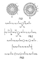
- the fiber has a core glass and a cladding glass with different refractive indices (not shown in FIGS. 1a and 1b).
- a fiber with a refractive index that gradually changes from the inside to the outside can be used and instead of a fiber drawn from a preform, a fiber produced with the double crucible process can be used.
- the glass fiber 1 shown in Fig. 1 has a circular cross-section (diameter 125 ⁇ m), but the cross-section can also be any other, e.g. have an elliptical shape.
- a layer of a curable plastic composition is applied thereon, which is then cured to form a buffer layer 2 made of a synthetic rubber with a thickness of 30 ⁇ m.
- the main constituent (76% by weight) of the curable plastic composition is a polyether urethane acrylate, as described in European patent application 167199 and shown in FIG. 2.
- the curable plastic composition furthermore has the reactive monomers 2-phenoxyethyl acrylate (14% by weight) and hexanediol diacrylate (2% by weight) and the photosensitive initiators 2,2-dimethoxy-2-phenylacetophenone (2% by weight), 2 , 2-dimethyl-2-hydroxy-azetophenone (2% by weight) and 2-oxybenzophenone-2-ethoxy-ethylazetophenone (2% by weight).
- the curable plastic composition has 2% by weight of a mixture of mono- and di-2 -Acryloxyäthylphosphat with a molar ratio of 1: 1.
- curable plastic compositions such as polysiloxanes
- the curable plastic composition is cured within a maximum of 0.5 seconds by irradiation with a high-pressure mercury lamp which generates UV light with wavelengths from 200 to 400 nm with an intensity of 0.27 W / cm 2 measured on the plastic layer. It is also possible to cure the curable plastic composition in a different way, for example by irradiation with electrons, in which case the curable plastic composition need not have a light-sensitive initiator.
- a second layer of plastic 3 with a thickness of 30 ⁇ m is then applied to the fiber (see FIG. 1a), for example by covering the fiber with a hardenable plastic composition which is then cured by irradiation with UV light becomes.
- a suitable commercially available plastic composition for the second layer is DeSolite 042 0 from DeSoto Inc., which has a light-sensitive initiator.
- the secondary plastic covering 4 is applied with a thickness of 300 pm.
- a curable plastic composition which has 98% by weight of a polyester urethane acrylate, as shown in FIG. 3, and which furthermore has 2% by weight of the light-sensitive initiator 1-hydroxy-1-methyl-ethylphenyl ketone.
- This plastic composition is applied at a temperature of 80 ° C on the Gals fiber with the primary plastic covering.
- the viscosity of the plastic composition at 80 ° C is 6.7 Pa.s.
- the curable plastic composition is subjected to a stretching flow, whereby the molecules are oriented. The order that arises in this way is determined by the crosslinking reaction during curing.
- the curable plastic composition is measured by irradiation with an electrodeless mercury lamp from Fusion Systems Inc. at an intensity of 0.27 W / cm 2 Plastic composition, hardened. By curing in a nitrogen atmosphere and at a temperature of 80 ° C, the curing time is less than 0.03 seconds.
- the orientation in the plastic layer 4 obtained in this way can be made visible using a polarizing microscope.
- Some properties measured on the anisotropic material are given in Table 1.
- the anisotropic material is characterized by a low axial expansion coefficient (linear thermal expansion coefficient) and a high axial modulus of elasticity and a high axial breaking strength.
- the material shows oriented crystallization.
- the melting temperature of the crystals is 70 ° C, which explains the low modulus of elasticity at 80 ° C. According to the invention, it is possible to use a material with a higher melting temperature of the crystals.
- the outer layer 5 of the primary plastic covering is made from the oriented plastic, e.g. manufactured with a thickness of 40 pm.
- the optical fiber can be covered with a subsequent layer of a thermoplastic, e.g. made of nylon, in the form of a tube 6, in which the fiber can move freely. A particularly temperature-insensitive fiber is thereby obtained.
- Fig. 4 shows a schematic section through a fiber covering device with an upper part 10 and a bottom part 11, these parts e.g. are connected to each other by means of a screw connection.
- the upper part 10 has a feed channel 12 through which a glass fiber 13 with the cladding layers that may already be present (not shown in the figure) can be fed.
- the upper part 10 and the bottom part 11 enclose a space 14.
- the curable plastic composition can be supplied through a feed opening 15 in the bottom part 11 and can be applied to the glass fiber 13 via the space 14 and an annular nozzle 16.
- the diameter of the annular nozzle 16 is larger than the diameter of the glass fiber 13 with the layers to be applied thereon.
- the transport speed of the glass fiber 13 in the downward direction is chosen to be so great that the liquid curable plastic composition is exposed to an expansion flow at the point indicated by the arrow 17 in the figure.
- a heating liquid e.g. Water with a temperature of 80 ° C
- an opening 21 which can be connected to a vacuum pump (not shown in the figure) in order to generate a vacuum in the space 22 between the glass fiber 13 and the supplied plastic composition.
Landscapes
- Chemical & Material Sciences (AREA)
- Life Sciences & Earth Sciences (AREA)
- Geochemistry & Mineralogy (AREA)
- Engineering & Computer Science (AREA)
- Chemical Kinetics & Catalysis (AREA)
- General Chemical & Material Sciences (AREA)
- General Life Sciences & Earth Sciences (AREA)
- Materials Engineering (AREA)
- Organic Chemistry (AREA)
- Physics & Mathematics (AREA)
- General Physics & Mathematics (AREA)
- Optics & Photonics (AREA)
- Surface Treatment Of Glass Fibres Or Filaments (AREA)
- Optical Fibers, Optical Fiber Cores, And Optical Fiber Bundles (AREA)
Applications Claiming Priority (2)
| Application Number | Priority Date | Filing Date | Title |
|---|---|---|---|
| NL8502402A NL8502402A (nl) | 1985-09-03 | 1985-09-03 | Optische vezel voorzien van een kunststofbedekking, en werkwijze en inrichting voor de vervaardiging van een dergelijke optische vezel. |
| NL8502402 | 1985-09-03 |
Publications (2)
| Publication Number | Publication Date |
|---|---|
| EP0213680A1 EP0213680A1 (de) | 1987-03-11 |
| EP0213680B1 true EP0213680B1 (de) | 1990-05-09 |
Family
ID=19846495
Family Applications (1)
| Application Number | Title | Priority Date | Filing Date |
|---|---|---|---|
| EP86201482A Expired - Lifetime EP0213680B1 (de) | 1985-09-03 | 1986-08-29 | Optische Faser mit Kunststoffbedeckung und Verfahren zum Herstellen einer derartigen optischen Faser |
Country Status (6)
| Country | Link |
|---|---|
| US (1) | US4733941A (nl) |
| EP (1) | EP0213680B1 (nl) |
| JP (1) | JPH0830777B2 (nl) |
| CA (1) | CA1269261A (nl) |
| DE (1) | DE3671005D1 (nl) |
| NL (1) | NL8502402A (nl) |
Families Citing this family (25)
| Publication number | Priority date | Publication date | Assignee | Title |
|---|---|---|---|---|
| NL8602337A (nl) * | 1986-09-16 | 1988-04-18 | Philips Nv | Werkwijze voor de vervaardiging van een optische vezel. |
| US4854668A (en) * | 1987-04-14 | 1989-08-08 | Siemens Aktiengesellschaft | Light waveguide having three protective layers of plastic material and a method of manufacture |
| US4851165A (en) * | 1987-09-02 | 1989-07-25 | American Telephone And Telegraph Company At&T Bell Laboratories | Methods of and apparatus for coating optical fiber |
| NL8702395A (nl) * | 1987-10-08 | 1989-05-01 | Philips Nv | Optische vezel voorzien van een kunststofbedekking. |
| DE3744465C1 (de) * | 1987-12-23 | 1989-02-09 | Siemens Ag | Vorrichtung und Verfahren zur Herstellung der Isolationsschicht einer Leitung |
| JPH0778564B2 (ja) * | 1988-03-09 | 1995-08-23 | 日立電線株式会社 | プラスチック光ファイバの製造方法 |
| GB8809595D0 (en) * | 1988-04-22 | 1988-05-25 | Bicc Plc | Method & apparatus for making optical fibre member |
| JP2775757B2 (ja) * | 1988-07-01 | 1998-07-16 | 東レ株式会社 | ポリマクラッド石英光ファイバコード |
| US4848869A (en) * | 1988-08-08 | 1989-07-18 | Corning Incorporated | Method of coating and optical fiber comprising polyimide-silicone block copolymer coating |
| US5205890A (en) * | 1989-02-28 | 1993-04-27 | At&T Bell Laboratories | Method for providing stable package of elongated optical fiber with bonded convolutions |
| US4950049A (en) * | 1989-02-28 | 1990-08-21 | At&T Bell Laboratories | Stable package of elongated optical fiber strand material |
| US5352712A (en) * | 1989-05-11 | 1994-10-04 | Borden, Inc. | Ultraviolet radiation-curable coatings for optical fibers |
| US5536529A (en) * | 1989-05-11 | 1996-07-16 | Borden, Inc. | Ultraviolet radiation-curable coatings for optical fibers and optical fibers coated therewith |
| CA1321671C (en) * | 1989-05-11 | 1993-08-24 | Paul J. Shustack | Ultraviolet radiation-curable coatings for optical fibers and optical fibers coated therewith |
| US4962992A (en) * | 1989-05-15 | 1990-10-16 | At&T Bell Laboratories | Optical transmission media and methods of making same |
| US5104433A (en) * | 1989-05-15 | 1992-04-14 | At&T Bell Laboratories | Method of making optical fiber |
| CA1341128C (en) * | 1989-06-27 | 2000-10-24 | Borden Chemical, Inc. | Optical fiber array |
| EP0423880B1 (en) * | 1989-10-18 | 1995-03-01 | Koninklijke Philips Electronics N.V. | Molecularly oriented synthetic resin composition |
| CN1119675C (zh) * | 1995-06-29 | 2003-08-27 | 皇家菲利浦电子有限公司 | 偏振元件和图像投影装置 |
| CN1183407C (zh) * | 1995-08-23 | 2005-01-05 | 皇家菲利浦电子有限公司 | 照明系统及含该照明系统的平板图像显示装置 |
| FR2764994B1 (fr) * | 1997-06-19 | 1999-08-06 | Alsthom Cge Alcatel | Conducteur optique et ruban de conducteurs optiques |
| AU2002225536A1 (en) | 2000-12-29 | 2002-07-16 | Dsm Ip Assets B.V. | Non-crystal-forming oligomers for use in radiation-curable fiber optic coatings |
| US7221826B2 (en) * | 2002-10-08 | 2007-05-22 | Tdk Corporation | Spot-size transformer, method of producing spot-size transformer and waveguide-embedded optical circuit using spot-size transformer |
| JP2004170924A (ja) * | 2002-11-05 | 2004-06-17 | Tdk Corp | 導波路埋め込み型光回路及びこれに用いる光学素子 |
| US8178020B2 (en) * | 2007-07-24 | 2012-05-15 | Pascale Industries, Inc. | Multicomponent textile fibers, methods for their production, and products made using them |
Family Cites Families (6)
| Publication number | Priority date | Publication date | Assignee | Title |
|---|---|---|---|---|
| US4127370A (en) * | 1975-05-14 | 1978-11-28 | The Post Office | Apparatus for forming dielectric optical waveguides |
| US3960530A (en) * | 1975-07-28 | 1976-06-01 | Northern Electric Company Limited | Method of coating a glass fiber filament |
| US4482204A (en) * | 1980-02-25 | 1984-11-13 | At&T Bell Laboratories | Ultraviolet absorbers in optical fiber coatings |
| US4502222A (en) * | 1982-12-06 | 1985-03-05 | Michael P. Breston | Shears for cutting sheet metal |
| US4474830A (en) * | 1982-12-29 | 1984-10-02 | At&T Bell Laboratories | Multiple coating of fibers |
| NL8303252A (nl) * | 1983-09-22 | 1985-04-16 | Philips Nv | Optische glasvezel voorzien van een eerste en een tweede bedekking. |
-
1985
- 1985-09-03 NL NL8502402A patent/NL8502402A/nl not_active Application Discontinuation
-
1986
- 1986-08-28 CA CA000517044A patent/CA1269261A/en not_active Expired - Lifetime
- 1986-08-29 DE DE8686201482T patent/DE3671005D1/de not_active Expired - Lifetime
- 1986-08-29 EP EP86201482A patent/EP0213680B1/de not_active Expired - Lifetime
- 1986-09-01 JP JP61203892A patent/JPH0830777B2/ja not_active Expired - Lifetime
- 1986-09-02 US US06/903,008 patent/US4733941A/en not_active Expired - Lifetime
Non-Patent Citations (1)
| Title |
|---|
| Electronic letters, Band 20, Seiten 841,842 (1984) Y. SHUTO et al. * |
Also Published As
| Publication number | Publication date |
|---|---|
| JPH0830777B2 (ja) | 1996-03-27 |
| JPS6259911A (ja) | 1987-03-16 |
| EP0213680A1 (de) | 1987-03-11 |
| NL8502402A (nl) | 1987-04-01 |
| CA1269261A (en) | 1990-05-22 |
| US4733941A (en) | 1988-03-29 |
| DE3671005D1 (de) | 1990-06-13 |
Similar Documents
| Publication | Publication Date | Title |
|---|---|---|
| EP0213680B1 (de) | Optische Faser mit Kunststoffbedeckung und Verfahren zum Herstellen einer derartigen optischen Faser | |
| EP0140415B1 (de) | Optische Glasfaser mit einer ersten und einer zweiten Bedeckung | |
| EP0167199B1 (de) | Optische Glasfaser mit einer Kunststoffbedeckung und Verfahren zum Herstellen derselben | |
| EP0151743B1 (de) | Optisches Übertragungselement | |
| DE60022957T2 (de) | Verfahren zur Herstellung von hochbeanspruchten Verbundteilen | |
| EP0155051B1 (de) | Optische Glasfaser mit einer Kunststoffbedeckung und Verfahren zur Herstellung derselben | |
| DE3106451A1 (de) | Herstellungsverfahren fuer eine optische faser mit einem durch uv-strahlung gehaerteten ueberzug | |
| DE3545089A1 (de) | Einadriges kabel aus einer verstaerkten optischen faser und verfahren zu seiner herstellung | |
| DE3122235A1 (de) | Verfahren zur erzeugung faserverstaerkter harzstrukturen | |
| EP0178736A1 (de) | Verfahren zum Herstellen einer optischen Faser mit einer Kunststoffbedeckung | |
| DE3016009A1 (de) | Verfahren zur erzeugung faserverstaerkter harzstrukturen | |
| DE69534649T2 (de) | Schlichtemittel für glasorgane, verwendungsverfahren und produkte daraus | |
| EP1456704A2 (de) | Optische festader und verfahren zu deren herstellung | |
| EP0260756B1 (en) | Method of manufacturing an optical fibre | |
| DE60101774T2 (de) | Optische Faserbeschichtung zur Erhöhung der Mikro-Biegefestigkeit | |
| DE69805520T3 (de) | Optische Faser mit einem Mantel und Verfahren zu dessen Herstellung | |
| EP0287016A2 (de) | Lichtwellenleiter mit drei Schutzschichten aus Kunststoffmaterial und Verfahren zu deren Herstellung | |
| EP0412242A1 (de) | Optische Faser | |
| DE3814298A1 (de) | Lichtwellenleiter | |
| EP0117594A2 (de) | Verfahren zur Herstellung einer Wellenleiterader und Vorrichtung zur Durchführung des Verfahrens | |
| DE4226343C2 (de) | Verfahren und Vorrichtung zur Herstellung einer optischen Faser | |
| WO2009015825A2 (de) | Verfahren sowie vorrichtung zum herstellen einer elastomeren lichtleitfaser sowie lichtleitfaser | |
| EP0469383A1 (de) | Optisches Ubertragungselement mit zweischichtiger Schutzhülle und Verfahren zu dessen Herstellung | |
| EP0212706B1 (de) | Optische Glasfaser mit einer Kunststoffbedeckung und härtbare Kunststoffzusammensetzung | |
| DE2944073C2 (de) | Lichtwellenleiter-Kabel und Verfahren zu seiner Herstellung |
Legal Events
| Date | Code | Title | Description |
|---|---|---|---|
| PUAI | Public reference made under article 153(3) epc to a published international application that has entered the european phase |
Free format text: ORIGINAL CODE: 0009012 |
|
| AK | Designated contracting states |
Kind code of ref document: A1 Designated state(s): DE FR GB IT NL SE |
|
| 17P | Request for examination filed |
Effective date: 19870702 |
|
| 17Q | First examination report despatched |
Effective date: 19881212 |
|
| GRAA | (expected) grant |
Free format text: ORIGINAL CODE: 0009210 |
|
| AK | Designated contracting states |
Kind code of ref document: B1 Designated state(s): DE FR GB IT NL SE |
|
| REF | Corresponds to: |
Ref document number: 3671005 Country of ref document: DE Date of ref document: 19900613 |
|
| ITF | It: translation for a ep patent filed |
Owner name: ING. C. GREGORJ S.P.A. |
|
| GBT | Gb: translation of ep patent filed (gb section 77(6)(a)/1977) | ||
| ET | Fr: translation filed | ||
| PGFP | Annual fee paid to national office [announced via postgrant information from national office to epo] |
Ref country code: SE Payment date: 19900828 Year of fee payment: 5 |
|
| PGFP | Annual fee paid to national office [announced via postgrant information from national office to epo] |
Ref country code: NL Payment date: 19900831 Year of fee payment: 5 |
|
| PLBE | No opposition filed within time limit |
Free format text: ORIGINAL CODE: 0009261 |
|
| STAA | Information on the status of an ep patent application or granted ep patent |
Free format text: STATUS: NO OPPOSITION FILED WITHIN TIME LIMIT |
|
| 26N | No opposition filed | ||
| PG25 | Lapsed in a contracting state [announced via postgrant information from national office to epo] |
Ref country code: SE Effective date: 19910830 |
|
| PG25 | Lapsed in a contracting state [announced via postgrant information from national office to epo] |
Ref country code: NL Effective date: 19920301 |
|
| NLV4 | Nl: lapsed or anulled due to non-payment of the annual fee | ||
| ITTA | It: last paid annual fee | ||
| EUG | Se: european patent has lapsed |
Ref document number: 86201482.6 Effective date: 19920306 |
|
| ITPR | It: changes in ownership of a european patent |
Owner name: CAMBIO RAGIONE SOCIALE;PHILIPS ELECTRONICS N.V. |
|
| REG | Reference to a national code |
Ref country code: FR Ref legal event code: CD |
|
| REG | Reference to a national code |
Ref country code: GB Ref legal event code: 732E |
|
| REG | Reference to a national code |
Ref country code: FR Ref legal event code: TP |
|
| PGFP | Annual fee paid to national office [announced via postgrant information from national office to epo] |
Ref country code: FR Payment date: 19990604 Year of fee payment: 14 |
|
| PGFP | Annual fee paid to national office [announced via postgrant information from national office to epo] |
Ref country code: GB Payment date: 19990825 Year of fee payment: 14 |
|
| PGFP | Annual fee paid to national office [announced via postgrant information from national office to epo] |
Ref country code: DE Payment date: 19991102 Year of fee payment: 14 |
|
| PG25 | Lapsed in a contracting state [announced via postgrant information from national office to epo] |
Ref country code: GB Free format text: LAPSE BECAUSE OF NON-PAYMENT OF DUE FEES Effective date: 20000829 |
|
| GBPC | Gb: european patent ceased through non-payment of renewal fee |
Effective date: 20000829 |
|
| PG25 | Lapsed in a contracting state [announced via postgrant information from national office to epo] |
Ref country code: FR Free format text: LAPSE BECAUSE OF NON-PAYMENT OF DUE FEES Effective date: 20010430 |
|
| PG25 | Lapsed in a contracting state [announced via postgrant information from national office to epo] |
Ref country code: DE Free format text: LAPSE BECAUSE OF NON-PAYMENT OF DUE FEES Effective date: 20010501 |
|
| REG | Reference to a national code |
Ref country code: FR Ref legal event code: ST |
|
| PG25 | Lapsed in a contracting state [announced via postgrant information from national office to epo] |
Ref country code: IT Free format text: LAPSE BECAUSE OF NON-PAYMENT OF DUE FEES;WARNING: LAPSES OF ITALIAN PATENTS WITH EFFECTIVE DATE BEFORE 2007 MAY HAVE OCCURRED AT ANY TIME BEFORE 2007. THE CORRECT EFFECTIVE DATE MAY BE DIFFERENT FROM THE ONE RECORDED. Effective date: 20050829 |