EP0213680B1 - Optical fibre with a synthetic coating, and process for making such an optical fibre - Google Patents
Optical fibre with a synthetic coating, and process for making such an optical fibre Download PDFInfo
- Publication number
- EP0213680B1 EP0213680B1 EP86201482A EP86201482A EP0213680B1 EP 0213680 B1 EP0213680 B1 EP 0213680B1 EP 86201482 A EP86201482 A EP 86201482A EP 86201482 A EP86201482 A EP 86201482A EP 0213680 B1 EP0213680 B1 EP 0213680B1
- Authority
- EP
- European Patent Office
- Prior art keywords
- synthetic resin
- plastic
- molecules
- curable
- oriented
- Prior art date
- Legal status (The legal status is an assumption and is not a legal conclusion. Google has not performed a legal analysis and makes no representation as to the accuracy of the status listed.)
- Expired - Lifetime
Links
Images

Classifications
-
- G—PHYSICS
- G02—OPTICS
- G02B—OPTICAL ELEMENTS, SYSTEMS OR APPARATUS
- G02B6/00—Light guides; Structural details of arrangements comprising light guides and other optical elements, e.g. couplings
- G02B6/44—Mechanical structures for providing tensile strength and external protection for fibres, e.g. optical transmission cables
- G02B6/4401—Optical cables
- G02B6/4402—Optical cables with one single optical waveguide
-
- C—CHEMISTRY; METALLURGY
- C03—GLASS; MINERAL OR SLAG WOOL
- C03C—CHEMICAL COMPOSITION OF GLASSES, GLAZES OR VITREOUS ENAMELS; SURFACE TREATMENT OF GLASS; SURFACE TREATMENT OF FIBRES OR FILAMENTS MADE FROM GLASS, MINERALS OR SLAGS; JOINING GLASS TO GLASS OR OTHER MATERIALS
- C03C25/00—Surface treatment of fibres or filaments made from glass, minerals or slags
- C03C25/10—Coating
- C03C25/104—Coating to obtain optical fibres
- C03C25/1065—Multiple coatings
-
- C—CHEMISTRY; METALLURGY
- C03—GLASS; MINERAL OR SLAG WOOL
- C03C—CHEMICAL COMPOSITION OF GLASSES, GLAZES OR VITREOUS ENAMELS; SURFACE TREATMENT OF GLASS; SURFACE TREATMENT OF FIBRES OR FILAMENTS MADE FROM GLASS, MINERALS OR SLAGS; JOINING GLASS TO GLASS OR OTHER MATERIALS
- C03C25/00—Surface treatment of fibres or filaments made from glass, minerals or slags
- C03C25/10—Coating
- C03C25/12—General methods of coating; Devices therefor
- C03C25/18—Extrusion
Definitions
- the invention relates to an optical fiber with plastic covering, with a glass fiber, a first cladding layer made of a synthetic rubber and a subsequent cladding layer made of a plastic, the molecules of which are mainly oriented in the longitudinal direction of the glass fiber.
- the invention further relates to a method and an apparatus for producing such an optical fiber.
- Glass fibers for optical communication are generally covered with a covering made of a plastic in order to avoid mechanical damage.
- a cladding is preferred which is made up of several layers.
- a first soft buffer layer made of synthetic rubber with an elastic modulus of 1 to 10 MPa is applied.
- a second, harder outer layer made of a plastic with an elastic modulus of over 100 MPa is applied.
- This outer layer is also applied immediately after the formation of the glass fiber, i.e. before the fiber is passed over a guide roller or before it is stored. The buffer layer and the outer layer together form the primary plastic covering of the glass fiber.
- the optical fiber In order to protect the optical fiber against environmental influences during the cabling, when laying the cables and during the life of the cable, the optical fiber is also provided with a thicker secondary plastic covering with an elastic modulus above 1 GPa. This secondary plastic covering will. not necessarily attached immediately after the fiber is formed.
- the optical fiber with the primary plastic covering is exposed in the secondary plastic covering, which consequently forms a tube.
- the space between the optical fiber and the tube is generally covered with a thixotropic liquid or a gel. e.g. a silicon oil filled with silicon dioxide.
- the secondary plastic covering is adhesively bonded to the primary plastic covering.
- micro diffraction losses of an optical fiber under transverse loading can be reduced without giving rise to great sensitivity to temperature by giving the molecules of part of the plastic covering a preferred orientation in the longitudinal direction or optical fiber.
- This increases the modulus of elasticity of the plastic in the longitudinal direction, while the coefficient of thermal expansion becomes smaller.
- the coefficient of thermal expansion of the gas fiber is preferably almost equal to that of the plastic.
- the invention has for its object to provide an optical fiber and a method for producing the same, as described at the beginning, the above-mentioned disadvantages being avoided.
- an optical fiber de type described above which further has the characteristic that the oriented plastic is formed from a curable plastic composition which has one or more oligomeric compounds, the molecules of which are provided with reactive groups and their Molecular weight is less than 5000.
- the oriented plastic layer can e.g. be the outer layer of the primary plastic cover or a tight-fitting secondary plastic cover. It is also possible to produce the outer layer of the primary plastic covering and the secondary plastic covering from an oriented plastic.
- the orientation of the polymer molecules in the cladding layer results in a high modulus of elasticity and a low coefficient of expansion of the plastic in the longitudinal direction of the optical fiber. Due to the low viscosity of the curable plastic composition, only a small pressure is required to apply it, which means that a high covering speed can be achieved and thin layers can also be applied.
- the application and curing of the plastic composition can be carried out at low temperature, e.g. below 100 ° C, so that the buffer layer of the primary plastic covering is not attacked.
- the application and curing of the plastic composition which no longer requires a tub of cooling water, can be carried out at such a speed that the covering of the glass fiber can take place in a single process step, including the secondary plastic covering, if this is formed from the curable plastic composition.
- a particular advantage of the optical fiber and the method according to the invention is that the outer layer of the primary plastic covering is no longer necessary and can therefore be dispensed with if the secondary plastic covering is applied in the form of an oriented plastic layer immediately after the formation of the fiber.
- the curable plastic composition used according to the invention must have reactive oligomeric molecules with a regular structure, whereby properties as from a liquid crystalline material are obtained.
- the molecular weight of the oligomeric compound must be less than 5000 in order to give the molecules sufficient mobility that they can align.
- the oligomeric compound is selected from the group formed by polyester urethane acrylates and polyether urethane acrylates. These compounds have such a regular structure that they are crystalline in the uncured state at room temperature.
- the curable plastic composition may further include reactive monomers and other common additives such as e.g. are described in European patent application 167199.
- the object of creating a method for producing an optical fiber is achieved according to the invention by a method in which a curable plastic composition which has one or more oligomeric compounds, the molecules thereof, is applied to a glass fiber with at least one coating layer made of synthetic rubber are provided with reactive groups and whose molecular weight is less than 5000, the molecules of the curable plastic composition being oriented when attached to the glass fiber, after which the curable plastic composition to form a plastic, the molecules of which are primarily oriented in the longitudinal direction of the optical fiber, for curing brought.
- the molecules of the oligomeric compound can be used during or after covering the glass fiber e.g. be oriented by shear forces in the liquid.
- a particularly effective orientation is obtained according to the invention in that the molecules of the curable plastic composition are oriented by means of an expansion flow when they are attached to the glass fiber. Elongation in the liquid is determined by the fiber pulling rate and the outflow rate of the curable plastic composition, e.g. can be regulated by means of the pressure.
- the curable plastic composition In order to determine the orientation of the molecules in the curable plastic composition by means of a crosslinking reaction, the curable plastic composition must be cured in a time that is shorter than the relaxation time of the molecules.
- the relaxation time of the molecules is determined by the size of the molecule and by the force of attraction between the molecules. Good results can be achieved with the oligomeric compounds described above and with reactive low-molecular liquid crystalline compounds.
- the curing of the curable plastic composition can e.g. by increasing the temperature, but the relaxation time or oriented molecules is shorter.
- the curable plastic composition is cured by actinic radiation.
- Actinic radiation is understood to mean, for example, irradiation with UV light, electrons, X-rays, gamma rays or with high-energy particles.
- curing times are shorter than 0.1 Second has been obtained.
- Particularly short curing times can be achieved by curing in a nitrogen atmosphere.
- a known advantage of using a radiation-curable plastic composition is the lack of solvents and other substances which have to be removed from the layer formed during or as a result of the curing. In the method according to the invention, this is very favorable not only for protecting the environment, but also for the curing speed and for maintaining the orientation of the molecules.
- EP-A-140415 describes optical glass fibers with a covering made of acrylic resin that is composed of two layers, but no orientation of the plastic is intended.
- a glass fiber is formed in a known manner by pulling it from a preform.
- glass fiber is a fiber made of glass or quartz glass.
- the fiber has a core glass and a cladding glass with different refractive indices (not shown in FIGS. 1a and 1b).
- a fiber with a refractive index that gradually changes from the inside to the outside can be used and instead of a fiber drawn from a preform, a fiber produced with the double crucible process can be used.
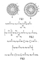
- the glass fiber 1 shown in Fig. 1 has a circular cross-section (diameter 125 ⁇ m), but the cross-section can also be any other, e.g. have an elliptical shape.
- a layer of a curable plastic composition is applied thereon, which is then cured to form a buffer layer 2 made of a synthetic rubber with a thickness of 30 ⁇ m.
- the main constituent (76% by weight) of the curable plastic composition is a polyether urethane acrylate, as described in European patent application 167199 and shown in FIG. 2.
- the curable plastic composition furthermore has the reactive monomers 2-phenoxyethyl acrylate (14% by weight) and hexanediol diacrylate (2% by weight) and the photosensitive initiators 2,2-dimethoxy-2-phenylacetophenone (2% by weight), 2 , 2-dimethyl-2-hydroxy-azetophenone (2% by weight) and 2-oxybenzophenone-2-ethoxy-ethylazetophenone (2% by weight).
- the curable plastic composition has 2% by weight of a mixture of mono- and di-2 -Acryloxyäthylphosphat with a molar ratio of 1: 1.
- curable plastic compositions such as polysiloxanes
- the curable plastic composition is cured within a maximum of 0.5 seconds by irradiation with a high-pressure mercury lamp which generates UV light with wavelengths from 200 to 400 nm with an intensity of 0.27 W / cm 2 measured on the plastic layer. It is also possible to cure the curable plastic composition in a different way, for example by irradiation with electrons, in which case the curable plastic composition need not have a light-sensitive initiator.
- a second layer of plastic 3 with a thickness of 30 ⁇ m is then applied to the fiber (see FIG. 1a), for example by covering the fiber with a hardenable plastic composition which is then cured by irradiation with UV light becomes.
- a suitable commercially available plastic composition for the second layer is DeSolite 042 0 from DeSoto Inc., which has a light-sensitive initiator.
- the secondary plastic covering 4 is applied with a thickness of 300 pm.
- a curable plastic composition which has 98% by weight of a polyester urethane acrylate, as shown in FIG. 3, and which furthermore has 2% by weight of the light-sensitive initiator 1-hydroxy-1-methyl-ethylphenyl ketone.
- This plastic composition is applied at a temperature of 80 ° C on the Gals fiber with the primary plastic covering.
- the viscosity of the plastic composition at 80 ° C is 6.7 Pa.s.
- the curable plastic composition is subjected to a stretching flow, whereby the molecules are oriented. The order that arises in this way is determined by the crosslinking reaction during curing.
- the curable plastic composition is measured by irradiation with an electrodeless mercury lamp from Fusion Systems Inc. at an intensity of 0.27 W / cm 2 Plastic composition, hardened. By curing in a nitrogen atmosphere and at a temperature of 80 ° C, the curing time is less than 0.03 seconds.
- the orientation in the plastic layer 4 obtained in this way can be made visible using a polarizing microscope.
- Some properties measured on the anisotropic material are given in Table 1.
- the anisotropic material is characterized by a low axial expansion coefficient (linear thermal expansion coefficient) and a high axial modulus of elasticity and a high axial breaking strength.
- the material shows oriented crystallization.
- the melting temperature of the crystals is 70 ° C, which explains the low modulus of elasticity at 80 ° C. According to the invention, it is possible to use a material with a higher melting temperature of the crystals.
- the outer layer 5 of the primary plastic covering is made from the oriented plastic, e.g. manufactured with a thickness of 40 pm.
- the optical fiber can be covered with a subsequent layer of a thermoplastic, e.g. made of nylon, in the form of a tube 6, in which the fiber can move freely. A particularly temperature-insensitive fiber is thereby obtained.
- Fig. 4 shows a schematic section through a fiber covering device with an upper part 10 and a bottom part 11, these parts e.g. are connected to each other by means of a screw connection.
- the upper part 10 has a feed channel 12 through which a glass fiber 13 with the cladding layers that may already be present (not shown in the figure) can be fed.
- the upper part 10 and the bottom part 11 enclose a space 14.
- the curable plastic composition can be supplied through a feed opening 15 in the bottom part 11 and can be applied to the glass fiber 13 via the space 14 and an annular nozzle 16.
- the diameter of the annular nozzle 16 is larger than the diameter of the glass fiber 13 with the layers to be applied thereon.
- the transport speed of the glass fiber 13 in the downward direction is chosen to be so great that the liquid curable plastic composition is exposed to an expansion flow at the point indicated by the arrow 17 in the figure.
- a heating liquid e.g. Water with a temperature of 80 ° C
- an opening 21 which can be connected to a vacuum pump (not shown in the figure) in order to generate a vacuum in the space 22 between the glass fiber 13 and the supplied plastic composition.
Landscapes
- Chemical & Material Sciences (AREA)
- Life Sciences & Earth Sciences (AREA)
- Geochemistry & Mineralogy (AREA)
- Engineering & Computer Science (AREA)
- Chemical Kinetics & Catalysis (AREA)
- General Chemical & Material Sciences (AREA)
- General Life Sciences & Earth Sciences (AREA)
- Materials Engineering (AREA)
- Organic Chemistry (AREA)
- Physics & Mathematics (AREA)
- General Physics & Mathematics (AREA)
- Optics & Photonics (AREA)
- Surface Treatment Of Glass Fibres Or Filaments (AREA)
- Optical Fibers, Optical Fiber Cores, And Optical Fiber Bundles (AREA)
Description
Die Erfindung bezieht sich auf eine optische Faser mit Kunststoffbedeckung, mit einer Glasfaser, einer ersten Umhüllungsschicht aus einem Kunstgummi und einer folgenden Umhüllungsschicht aus einem Kunststoff, dessen Moleküle hauptsächlich in der Längsrichtung der Glasfaser orientiert sind.The invention relates to an optical fiber with plastic covering, with a glass fiber, a first cladding layer made of a synthetic rubber and a subsequent cladding layer made of a plastic, the molecules of which are mainly oriented in the longitudinal direction of the glass fiber.
Die Erfindung bezieht sich weiterhin auf ein Verfahren und auf eine Vorrichtung zum Herstellen einer derartigen optischen Faser.The invention further relates to a method and an apparatus for producing such an optical fiber.
Glasfasern für die optische Nachrichtenübertragung werden im allgemeinen mit einer Umhüllung aus einem Kunststoff bedeckt, um mechanische Beschädigungen zu vermeiden. Um optische Übertragungsverluste infolge von Mikrobeugungen zu vermeiden, wird eine Umhüllung bevorzugt, die aus mehreren Schichten aufgebaut ist. Dabei wird z.B. folgendes Verfahren angewandt: Unmittelbar nach der Bildung der Glasfaser, z.B. durch Ziehen aus einer Vorform oder das Doppeltiegelverfahren, wird eine erste weiche Pufferschicht aus einem Kunstgummi mit einem Elastizitätsmodul von 1 bis 10 MPa angebracht. Um diese weiche Pufferschicht während der weiteren Verarbeitung der optischen Faser zu schützen, wird eine zweite härtere Aussenschicht aus einem Kunststoff mit einem Elastizitätsmodul über 100 MPa angebracht. Auch diese Aussenschicht wird unmittelbar nach der Bildung der Glasfaser angebracht, d.h. bevor die Faser über ein Führungsrolle geführt wird oder bevor sie gelagert wird. Die Pufferschicht und die Aussenschicht bilden zusammen die primäre Kunststoffbedeckung der Glasfaser.Glass fibers for optical communication are generally covered with a covering made of a plastic in order to avoid mechanical damage. In order to avoid optical transmission losses due to micro diffraction, a cladding is preferred which is made up of several layers. Here, e.g. following procedure: Immediately after the formation of the glass fiber, e.g. by pulling from a preform or the double-crucible process, a first soft buffer layer made of synthetic rubber with an elastic modulus of 1 to 10 MPa is applied. In order to protect this soft buffer layer during the further processing of the optical fiber, a second, harder outer layer made of a plastic with an elastic modulus of over 100 MPa is applied. This outer layer is also applied immediately after the formation of the glass fiber, i.e. before the fiber is passed over a guide roller or before it is stored. The buffer layer and the outer layer together form the primary plastic covering of the glass fiber.
Um die optische Faser währen der Verkabelung, beim Verlegen der Kabel und während der Lebensdauer der Kabel gegen Umwelteinflüsse zu schützen, wird die optische Faser ausserdem mit einer dickeren sekundären Kunststoffbedeckung mit einem Elastizitätsmodul über 1 GPa versehen. Diese sekundäre Kunststoffbedeckung wird. nicht unbedingt unmittelbar nach der Bildung der Glasfaser angebracht.In order to protect the optical fiber against environmental influences during the cabling, when laying the cables and during the life of the cable, the optical fiber is also provided with a thicker secondary plastic covering with an elastic modulus above 1 GPa. This secondary plastic covering will. not necessarily attached immediately after the fiber is formed.
Es werden zwei Ausführungsformen einer derartigen sekundären Kunststoffbedeckung angewendet. Bei der einen Ausführungsform liegt die optische Faser mit der primären Kunststoffbedeckung frei in der sekundären Kunststoffbedeckung, die folglich einen Schlauch bildet. Der Raum zwischen der optischen Faser und dem Schlauch wird dabei im allgemeinen mit einer thixotropen Flüssigkeit oder einem Gel. z.B. einem mit Siliziumdioxid gefüllten Silikonöl, gefüllt. Bei der anderen Ausführungsform ist die sekundäre Kunststoffbedeckung mit der primären Kunststoffbedeckung haftend verbunden.Two embodiments of such a secondary plastic covering are used. In one embodiment, the optical fiber with the primary plastic covering is exposed in the secondary plastic covering, which consequently forms a tube. The space between the optical fiber and the tube is generally covered with a thixotropic liquid or a gel. e.g. a silicon oil filled with silicon dioxide. In the other embodiment, the secondary plastic covering is adhesively bonded to the primary plastic covering.
Es ist bekannt, dass die Mikrobeugungsverluste einer optischen Faser unter Querbelastung verringert werden können, ohne dabei eine grosse Temperaturetempfindlichkeit entstehen zu lassen, indem man dan Molekülen eines Teils der Kunststoffbedeckung eine bevorzugte Orientierung in der Längsrichtung oder optischen Faser erteilt. Dadurch wird der Elastizitätsmodul des Kunststoffes in der Längsrichtung vergrössert, während der thermische Ausdehnungdkoeffizient kleiner wird. Vorzugsweise ist der thermische Ausdehnungskoeffizient der Gasfaser nahezu gleich dem des Kunststoffes.It is known that the micro diffraction losses of an optical fiber under transverse loading can be reduced without giving rise to great sensitivity to temperature by giving the molecules of part of the plastic covering a preferred orientation in the longitudinal direction or optical fiber. This increases the modulus of elasticity of the plastic in the longitudinal direction, while the coefficient of thermal expansion becomes smaller. The coefficient of thermal expansion of the gas fiber is preferably almost equal to that of the plastic.
In einer Veröffentlichung von Y. Shuto et al. in Electronics Letters Band 20, Seiten 841-842 (1984) wird die Herstellung einer derartigen optischen Faser beschrieben, wobei eine Glasfaser mit einer Pufferschicht aus einem Silikonkautschuk bedeckt wird. Danach wird eine Umhüllung aus einem flüssigkristallinen Polyester auf der Faser angebracht, und zwar durch Extrusion bei einer Temperatur über 240°C, wobei Orientierung der Polyestermoleküle durch Abscheren während der Extrusion erhalten wird. Die Orientierung wird durch Abkühlung des geschmolzenen Polyestres festgelegt, wobei dieses in den festen Zustand übergeht.In a publication by Y. Shuto et al. Electronics Letters
Dieses bekannte Verfahren weist jedoch mehrere Nachteile auf. Durch die hohe Temperatur beim Extrusionsverfahren wird die Auswahlmöglichkeit an geeigneten Materialien für die Pufferschicht eingeschränkt. So kann z.B. bei Polyurethankautschuk bei der Extrusion einer folgenden Schicht eine thermische Zersetzung auftreten. Wegen der hohen Temperatur ist ausserdem eine lange Kühlstrecke notwendig, bevor die Faser weiterverarbeitet oder aufgewickelt werden kann. Bei Abkühlung durch strömendes Wasser ist bei in der Technik üblichen Schichtdicken und Faserbedeckungsgeschwindigkeiten eine Kühlwanne mit einer Länge von über 5 m notwendig. Dies ist insbesondere nachteilig, wenn beabsichtigt wird, auch die sekundäre Kunststoffbedeckung unmittelbar nach den Ziehen der Glasfaser anzubringen. Eine weiterer Nachteil beruht auf der hohen Viskosität (über 100 Pa.s) des geschmolzenen Kunststoffes. Die Faserbedeckungsgeschwindigkeit wird durch den höchsten Druck, der bei der Extrusion angelegt werden kann, um den Kunststoff zu transportieren, beschränkt. Insbesondere beim Anbringen einer dünnen Unhüllung durch eine enge Düse ist der Druck ein beschränkender Faktor.However, this known method has several disadvantages. The high temperature during the extrusion process limits the choice of suitable materials for the buffer layer. For example, in the case of polyurethane rubber, thermal decomposition occurs during the extrusion of a subsequent layer. Because of the high temperature, a long cooling section is also necessary before the fiber can be further processed or wound up. When cooling by flowing water, a cooling trough with a length of more than 5 m is necessary at the layer thicknesses and fiber covering speeds that are common in industry. This is particularly disadvantageous if it is intended to also attach the secondary plastic cover immediately after the glass fiber has been pulled. Another disadvantage is the high viscosity (over 100 Pa.s) of the melted plastic. The fiber covering speed is limited by the highest pressure that can be applied during extrusion to transport the plastic. Pressure is a limiting factor, especially when applying a thin coating through a narrow nozzle.
Die Erfindung hat die Aufgabe, eine optische Faser und ein Verfahren zum Herstellen derselben zu schaffen, wie dies eingangs beschrieben wird, wobei die obenstehend genannten Nachteile vermieden werden.The invention has for its object to provide an optical fiber and a method for producing the same, as described at the beginning, the above-mentioned disadvantages being avoided.
Diese Aufgabe wird nach der Erfindung durch eine optische Faser de eingangs beschriebenen Art gelöst, die weiterhin das Kennzeichen aufweist, dass der orientierte Kunststoff aus einer härtbaren Kunststoffzusammensetzung gebildet ist, die eine oder mehrere oligomere Verbindungen aufweist, deren Moleküle mit reaktiven Gruppen versehen sind und deren Molekulargewicht kliener als 5000 ist.This object is achieved according to the invention by an optical fiber de type described above, which further has the characteristic that the oriented plastic is formed from a curable plastic composition which has one or more oligomeric compounds, the molecules of which are provided with reactive groups and their Molecular weight is less than 5000.
Es ist zwar bekannt, Glasfasern für die optische Nachrichtenübertragung unmittelbar nach der Bildung der Glasfaser mit einer härtbaren Kunststoffzusammensetzung zu bedecken und diese dann zum Aushärten zu bringen, namentlich zur Herstellung der primären Kunststoffbedeckung siehe z.B. die nicht vorveröffentliche Europäische Patentanmeldung 167199. In derartigen Fällen wird jedoch eine Schicht aus einem Kunststoff gebildet, die keine besondere Orientierung in der Längsrichtung der Glasfaser aufweist.Although it is known to cover glass fibers for optical communication immediately after the formation of the glass fiber with a curable plastic composition and then to cause it to harden, specifically for the production of the primary plastic cover, see for example the unpublished European patent application 167199. However, in such cases a layer off formed of a plastic that has no particular orientation in the longitudinal direction of the glass fiber.
Im Rahmen der Erfindung gibt es mehrere Möglichkeiten für die Lage der Umhüllungsschicht aus orientiertem Kunststoff. Die orientierte Kunststoffschicht kann z.B. die Aussenschicht der primären Kunststoffbedeckung sein oder eine eng anliegende sekundäre Kunststoffbedeckung. Auch ist es möglich die Aussenschicht der primären Kunststoffbedeckung sowie die sekundäre Kunststoffbedeckung aus einem orientierten Kunststoff herzustellen.Within the scope of the invention there are several possibilities for the position of the covering layer made of oriented plastic. The oriented plastic layer can e.g. be the outer layer of the primary plastic cover or a tight-fitting secondary plastic cover. It is also possible to produce the outer layer of the primary plastic covering and the secondary plastic covering from an oriented plastic.
Durch die Orientierung der Polymermoleküle in de Umhüllungsschicht werden ein hoher Elastizitätsmodul und ein niedriger Ausdehnungskoeffizient des Kunststoffes in der Längsrichtung der optischen Faser erhalten. Durch die niedrige Viskosität der härtbaren Kunststoffzusammensetzung ist zum Anbringen derselben nur ein geringer Druck notwendig, wodurch eine grosse Bedeckungsgeschwindigkeit erzielbar ist und wobei auch dünne Schichten angebracht werden können. Das Anbringen und Aushärten der Kunststoffzusammensetzung kann bei niedriger Temperatur, z.B. unter 100°C erfolgen, wodurch die Pufferschicht der primären Kunststoffbedeckung nicht angegriffen wird. Das Anbringen und Aushärten der Kunststoffzusammensetzung, wobei nun keine Wanne mit Kühlwasser mehr notwendig ist, kann mit einer derartigen Geschwindigkeit erfolgen, dass das Bedecken der Glasfaser in einem einzigen Verfahrenschritt erfolgen kann, einschliesslich der sekundären Kunststoffbedeckung, wenn diese aus der härtbaren Kunststoffzusammensetzung gebildet wird.The orientation of the polymer molecules in the cladding layer results in a high modulus of elasticity and a low coefficient of expansion of the plastic in the longitudinal direction of the optical fiber. Due to the low viscosity of the curable plastic composition, only a small pressure is required to apply it, which means that a high covering speed can be achieved and thin layers can also be applied. The application and curing of the plastic composition can be carried out at low temperature, e.g. below 100 ° C, so that the buffer layer of the primary plastic covering is not attacked. The application and curing of the plastic composition, which no longer requires a tub of cooling water, can be carried out at such a speed that the covering of the glass fiber can take place in a single process step, including the secondary plastic covering, if this is formed from the curable plastic composition.
Ein besonderer Vorteil der optischen Faser und des Verfahrens nach der Erfindung ist, dass die Aussenschicht der primären Kunststoffbedeckung nicht mehr notwendig ist und folglich darauf verzichtet werden kann, wenn die sekundäre Kunststoffbedeckung unmittelbar nach der Bildung der Faser in Form einer orientierten Kunststoffschicht angebracht wird.A particular advantage of the optical fiber and the method according to the invention is that the outer layer of the primary plastic covering is no longer necessary and can therefore be dispensed with if the secondary plastic covering is applied in the form of an oriented plastic layer immediately after the formation of the fiber.
Durch die anisotropen Eigenschaften des orientierten Kunststoffes führt eine Wasserabsorption in der Kunststoffbedeckung hauptsächlich zu einer Volumenvergrösserung in der Richtung quer zu der Glasfaser. Die optische Faser ist dadurch weniger empfindlich für optische Dämpfung infolge von Wasserabsorption als eine optische Faser mit einer isotropen Kunststoffbedeckung.Due to the anisotropic properties of the oriented plastic, water absorption in the plastic covering mainly leads to an increase in volume in the direction transverse to the glass fiber. This makes the optical fiber less sensitive to optical attenuation due to water absorption than an optical fiber with an isotropic plastic covering.
Die härtbare Kunststoffzusammensetzung, die nach der Erfindung verwendet wird, muss reaktive oligomere Moleküle mit einem regelmässigen Aufbau aufweisen, wodurch Eigenschaften wie von einem flüssigkristallinen Material erhalten werden. Das Molekulargwicht der oligomeren Verbindung muss kleiner als 5000 sein, um den Molekülen eine Mobilität zu erteilen, die ausreicht, dass sie sich ausrichten können.The curable plastic composition used according to the invention must have reactive oligomeric molecules with a regular structure, whereby properties as from a liquid crystalline material are obtained. The molecular weight of the oligomeric compound must be less than 5000 in order to give the molecules sufficient mobility that they can align.
In der optischen Faser und in dem Verfahren nach der Erfindung ist die oligomere Verbindung aus der Gruppe gewählt, die durch Polyesterurethanakrylate und Polyätherurethanakrylate gebildet ist. Diese Verbindungen haben einen derart regelmässigen Aufbau, dass sie in nicht ausgehärtetem Zustand bei Raumptemperatur kristallin sind. Die härtbare Kunststoffzusammensetzung kann weiterin reaktive Monomere und andere übliche Zusätze aufweisen, wie diese z.B. in der europäischen Patentanmeldung 167199 beschrieben sind.In the optical fiber and in the method according to the invention, the oligomeric compound is selected from the group formed by polyester urethane acrylates and polyether urethane acrylates. These compounds have such a regular structure that they are crystalline in the uncured state at room temperature. The curable plastic composition may further include reactive monomers and other common additives such as e.g. are described in European patent application 167199.
Die Aufgabe, ein Verfahren zum Herstellen einer optischen Faser zu schaffen, wird nach der Erfindung durch ein Verfahren gelöst, bei dem auf einer Glasfaser mit mindestens einer Umhüllungsschicht aus einem Kunstgummi eine härtbare Kunststoffzusammensetzung angebracht wird, die eine oder mehrere oligomere Verbindungen aufweist, deren Moleküle mit reaktiven Gruppen versehen sind und deren Molekulargewicht kleiner als 5000 ist, wobei die Moleküle der härtbaren Kunststoffzusammensetzung beim Anbringen auf der Glasfaser orientiert werden, wonach die härtbare Kunststoffzusammensetzung unter Bildung eines Kunststoffes, dessen Moleküle hauptsäuchlich in der Längsrichtung der optischen Faser orientieren sind, zum Aushärten gebracht wird.The object of creating a method for producing an optical fiber is achieved according to the invention by a method in which a curable plastic composition which has one or more oligomeric compounds, the molecules thereof, is applied to a glass fiber with at least one coating layer made of synthetic rubber are provided with reactive groups and whose molecular weight is less than 5000, the molecules of the curable plastic composition being oriented when attached to the glass fiber, after which the curable plastic composition to form a plastic, the molecules of which are primarily oriented in the longitudinal direction of the optical fiber, for curing brought.
Die Moleküle der oligomeren Verbindung können während oder nach der Bedeckung der Glasfaser z.B. durch Abscherkräfte in der Flüssigkeit orientiert werden. Eine besonders wirksame Orientierung wird nach der Erfindung dadurch erhalten, dass die Moleküle der härtbaren Kunststoffzusammensetzung beim Anbringen auf der Glasfaser mittels einer Dehnungsströmung orientiert werden. Die Dehnung in der Flüssigkeit wird durch die Faserziehgeschwindigkeit und die Ausströmungsgeschwindgkeit der härtbaren Kunststoffzusammensetzung bestimmt, die z.B. mittels des Druckes geregelt werden kann.The molecules of the oligomeric compound can be used during or after covering the glass fiber e.g. be oriented by shear forces in the liquid. A particularly effective orientation is obtained according to the invention in that the molecules of the curable plastic composition are oriented by means of an expansion flow when they are attached to the glass fiber. Elongation in the liquid is determined by the fiber pulling rate and the outflow rate of the curable plastic composition, e.g. can be regulated by means of the pressure.
Um eine Lunkerbildung in der Kunststoffbedeckung zu vermeiden, empfiehlt es sich, dass in dem Raum zwischen der Glasfaser und der zugeführten Kunststoffzusammensetzung ein Unterdruck erzeugt wird.In order to avoid the formation of voids in the plastic covering, it is recommended that a negative pressure be generated in the space between the glass fiber and the supplied plastic composition.
Um die Orientierung de Moleküle in der härtbaren Kunststoffzusammensetzung mittels einer Vernetzungsreaktion festzulegen, muss die härtbare Kunststoffzusammensetzung in einer Zeit ausgehärtet werden, die kürzer ist als die Relaxationszeit der Moleküle. Die Relaxationszeit der Moleküle wird durch die Molekülgrösse und durch die Anziehungskraft zwischen den Molekülen bestimmt. Mit den obenstehend beschriebenen oligomeren Verbindungen und mit reaktiven niedrigmolekularen flüssig kristallinen Verbindungen lassen sich gute Resulate erzielen.In order to determine the orientation of the molecules in the curable plastic composition by means of a crosslinking reaction, the curable plastic composition must be cured in a time that is shorter than the relaxation time of the molecules. The relaxation time of the molecules is determined by the size of the molecule and by the force of attraction between the molecules. Good results can be achieved with the oligomeric compounds described above and with reactive low-molecular liquid crystalline compounds.
Das Aushärten der härbaren Kunststoffzusammensetzung kann z.B. durch Erhöhung der Temperatur erfolgen, wobei jedoch die Relaxationszeit oder orientierten Moleküle kürzer wird.The curing of the curable plastic composition can e.g. by increasing the temperature, but the relaxation time or oriented molecules is shorter.
Bei einer bevorzugenten Ausführungsform des erfindungsgemässen Verfahrens wird die härtbare Kunststoffzusammensetzung dirch aktinische Strahlung zum Aushärten gebracht. Unter aktinischer Strahlung ist z.B. eine Bestrahlung mit UV-Licht, Elektronen, Röntgenstrahlung, Gammastrahlen oder mit hochenergetischen Teilchen zu verstehen. Bei Bestrahlung mit UV-Licht sind Aushärtezeiten kürzer als 0,1 Sekunde erhalten worden. Besonders kurze Aushärtezeiten lassen sich durch Aushärtung in einer Stickstoffatmosphäre erzielen. Est ist zweckmässig, die Bestrahlungsvorrichtung in einem möglichst kurzen Abstand von der Faserbedeckungsvorrichtung anzuordnen, damit Orientierungsverluste der gerichteten Moleküle beschränkt werde. Ein an sich bekannter Vorteil der Verwendung einer durch Strahlung härtbaren Kunststoffzusammensetzung ist das Fehlen von Lösungsmitteln und anderen Stoffen, die während oder infolge der Aushärtung aus der gebildeten Schicht abgeführt werden müssen. Beim erfindungsgemäßen Verfahren ist dies nicht zur zum Schutz der Umwelt, sondern auch für die Aushärtegeschwindigkeit und die Beibehaltung der Orientierung der Moleküle sehr günstig.In a preferred embodiment of the method according to the invention, the curable plastic composition is cured by actinic radiation. Actinic radiation is understood to mean, for example, irradiation with UV light, electrons, X-rays, gamma rays or with high-energy particles. When irradiated with UV light, curing times are shorter than 0.1 Second has been obtained. Particularly short curing times can be achieved by curing in a nitrogen atmosphere. It is expedient to arrange the radiation device as short as possible from the fiber covering device, so that loss of orientation of the directed molecules is limited. A known advantage of using a radiation-curable plastic composition is the lack of solvents and other substances which have to be removed from the layer formed during or as a result of the curing. In the method according to the invention, this is very favorable not only for protecting the environment, but also for the curing speed and for maintaining the orientation of the molecules.
In der europäischen Patentanmeldung EP-A-140415 sind optische Glasfaser mit einem aus zwei Schichten aufgebauten Bedeckung aus Akrylatharz beschrieben worden, wobei aber keine Orientierung des Kunststoffes beabsichtigt wird.European patent application EP-A-140415 describes optical glass fibers with a covering made of acrylic resin that is composed of two layers, but no orientation of the plastic is intended.
Glasfaser mit orientierten Kunststoffbedeckungen sind beschrieben worden in Patents Abstracts of Japan, Band 8, Nr. 222 (C-246),1659, Seite 246, übereinstimmend mitJP 59-107943 (Kokai) und in der US Patentschrift 4127370. Dabei werden aber polymere Moleküle orientiert und nicht, wie nach der Erfindung, oligomere Moleküle im orientieren Zustand gebracht und dann polymerisiert.Glass fiber with oriented plastic coverings have been described in Patent Abstracts of Japan, Vol. 8, No. 222 (C-246), 1659, page 246, in accordance with JP 59-107943 (Kokai) and in US Pat. No. 4127370. However, polymer molecules are thereby oriented and not, as according to the invention, brought oligomeric molecules in the oriented state and then polymerized.
Ausführungsbeispiele der Erfindung sind in der Zeichnung dargestellt und werden im folgenden näher beschrieben. Es zeigen:
- Fig. 1a und 1b Schnitte (nicht maßgerecht durch unterschiedliche Ausführungsformen einer optischen Faser nach der Erfindung,
- Fig. 2 die Strukturformel eines Polyätherurethanakrylats,
- Fig. 3 die Strukturformel eines Polyesterurethanakrylats und
- Fig. 4 einen Schnitt durch ein Vorrichtung zum Ausführen des Verfahrens nach der Erfindung.
- 1a and 1b sections (not to size by different embodiments of an optical fiber according to the invention,
- 2 shows the structural formula of a polyether urethane acrylate,
- Fig. 3 shows the structural formula of a polyester urethane acrylate and
- Fig. 4 shows a section through an apparatus for performing the method according to the invention.
Es wird auf bekannte Weise eine Glasfaser gebildet, indem diese aus einer Vorform gezogen wird. Unter Glasfaser ist in diesem Zusammenhang eine Faser aus Glas oder Quarzglas zu verstehen. Die Faser wiest ein Kernglas und ein Mantelglas mit unterschiedlichen Brechzahlen auf (in den Fig. 1a und 1b nicht dargestellt). Statt dessen kann auch eine Faser mit einer von innen nach aussen sich allmählich ändernden Brechzahl verwendet werden und statt einer aus einer Vorform gezogenen Faser kann eine mit dem Doppeltiegelverfahren hergestellte Faser verwendet werden. Die in Fig. 1 dargestellte Glasfaser 1 hat einen kreisförmigen Querschnitt (Durchmesser 125 pm), aber der Querschnitt kann auch eine beliebige andere, z.B. elliptische Form haben.A glass fiber is formed in a known manner by pulling it from a preform. In this context, glass fiber is a fiber made of glass or quartz glass. The fiber has a core glass and a cladding glass with different refractive indices (not shown in FIGS. 1a and 1b). Instead, a fiber with a refractive index that gradually changes from the inside to the outside can be used and instead of a fiber drawn from a preform, a fiber produced with the double crucible process can be used. The
Unmittelbar nach der Bildung der Glasfaser 1 wird darauf eine Schicht aus einer härtbaren Kunststoffzusammensetzung angebracht, die danach unter Bildung einer Pufferschicht 2 aus einem Kunstgummi mit einer Dicke von 30 pm ausgehärtet wird. Die härtbare Kunststoffzusammensetzung weist als Hauptbestandteil (76 Gew.%) ein Polyätherurethanakrylat auf, wie dies in der europäischen Patentanmeldung 167199 beschrieben und in Fig. 2 dargestellt ist. Die härtbare Kunststoffzusammensetzung weist weiterhin die reaktiven Monomere 2-Phenoxy-äthylakrylat (14 Gew.%) und Hexandioldiakrylat (2 Gew.%) und die lichtempfindlichen Initiatoren 2,2-Dimethoxy-2-phenyl- azetophenon (2 Gew.%), 2,2-Dimethyl-2-hydroxy-azetophenon (2 Gew.%) und 2-Oxybenzophenon-2- äthoxy-äthylazetophenone (2 Gew.%) Ausserdem weist die härtbare Kunststoffzusammensetzung 2 Gew.% eines Gemisches aus Mono- und Di-2-Akryloxyäthylphosphat mit einem Molverhältnis von 1:1 auf. Auch andere härtbare Kunststoffzusammensetzung, wie z.B. Polysiloxane, eignen sich dazu, als - Pufferschict der Kunststoffbedeckung der Glasfaser nach der Erfindung verwendet zu werden. Die härtbare Kunststoffzusammensetzung wird mittels Bestrahlung mit einer Hochdruckquecksilberlampe, die UV-Licht mit Wellenlängen von 200 bis 400 nm erzeugt mit einer Intensität von 0,27 W/cm2 gemessen auf der Kunststoffschicht, innerhalb maximal 0,5 Sekunde zum Aushärten gebracht. Est ist auch möglich, die härtbare Kunststoffzusammensetzung auf eine andere Art und Weise auszuhärten, z.B. durch Bestrahlung mit Elektronen, wobei dann die härtbare Kunststoffzusammensetzung keinen lichtempfindlichen Initiator aufzuweisen braucht.Immediately after the formation of the
Danach wird eine zweite Schicht aus einem Kunststoff 3 mit einer Dicke von 30 um auf der Faser angebracht (siehe Fig. 1a), z.B. dadurch, dass die Faser mit einer härtbaren Kunststoffzusammensetzung bedeckt wird, die danach durch Bestrahlung mit UV-Licht zum Aushärten gebracht wird. Eine geeignete handelsübliche Kunststoffzusammensetzung für die zweite Schicht (Aussensicht der primären Kunststoffbedeckung) ist DeSolite 0420 von DeSoto Inc., die einen lichtempfindlichen Initiator aufweist.A second layer of
Danach wird die sekundäre Kunststoffbedeckung 4 mit eine Dicke von 300 pm angebracht. Dazu wird eine härtbare Kunststoffzusammensetzung verwendet die 98 Gew.% eines Polyesterurethanakrylats aufweist, wie dies in Fig. 3 dargestellt ist, und die weitherhin 2 Gew.% des lichtempfindlichen Initiators 1-Hydroxy-1-methyl-äthylphenylketon aufweist. Diese Kunststoffzusammensetzung wird bei einer Temperatur von 80°C auf der Galsfaser mit der primären Kunstoffbedeckung angebracht. Die Viskosität der Kunststoffzusammensetzung bei 80°C beträgt 6,7 Pa.s. Beim Anbringen wird die härtbare Kunststoffzusammensetzung einer Dehnungsströmung ausgesetzt, wodurch die Moleküle orientiert werden. Die Ordnung, die auf diese Weise entsteht, wird durch die Vernetzungsreaktion beim Aushärten festgelegt. Die härtbare Kunststoffzusammensetzung wird durch Bestrahlung mit einer elektrodenlosen Quecksilberlampe von Fusion Systems Inc. mit einer Intensität von 0,27 W/cm2, gemessen auf der Kunststoffzusammensetzung, ausgehärtet. Dadurch, dass in einer Stickstoffatmosphäre und bei einer Temperatur von 80°C ausgehärtet wird, ist die Aushärtezeit kürzer als 0,03 Sekunde.Then the secondary plastic covering 4 is applied with a thickness of 300 pm. For this purpose, a curable plastic composition is used which has 98% by weight of a polyester urethane acrylate, as shown in FIG. 3, and which furthermore has 2% by weight of the light-sensitive initiator 1-hydroxy-1-methyl-ethylphenyl ketone. This plastic composition is applied at a temperature of 80 ° C on the Gals fiber with the primary plastic covering. The viscosity of the plastic composition at 80 ° C is 6.7 Pa.s. When attached, the curable plastic composition is subjected to a stretching flow, whereby the molecules are oriented. The order that arises in this way is determined by the crosslinking reaction during curing. The curable plastic composition is measured by irradiation with an electrodeless mercury lamp from Fusion Systems Inc. at an intensity of 0.27 W / cm 2 Plastic composition, hardened. By curing in a nitrogen atmosphere and at a temperature of 80 ° C, the curing time is less than 0.03 seconds.
Die Orientierung in der auf diese Wiese erhaltenen Kunststoffschicht 4 kann mit Hilfe eines Polarisationsmikroskops sichtbar gemacht werden. Einige an dem anisotropen Material gemessene Eigenschaften sind in Tabelle 1 angegeben.

Das anisotrope Material kennzeichnet sich durch einen niedrigen axialen Ausdehnungskoeffizienten (linearer thermischer) Ausdehnungskoeffizient) und einen hohen axialen Elastizitätsmodul une eine hohe axiale Bruchfestigkeit. Das Material weist orientierte Kristallisierung auf. In diesem Ausführungsbeispiel liegt die Schmelztemperatur der Kristalle bei 70°C, was den niedrigen Elastizitätsmodul bei 80°C erklärt. Nach der Erfindung ist es möglich, ein Material mit einer höheren Schmelztemperatur der Kristalle zu verwendet.The anisotropic material is characterized by a low axial expansion coefficient (linear thermal expansion coefficient) and a high axial modulus of elasticity and a high axial breaking strength. The material shows oriented crystallization. In this embodiment, the melting temperature of the crystals is 70 ° C, which explains the low modulus of elasticity at 80 ° C. According to the invention, it is possible to use a material with a higher melting temperature of the crystals.
In einer alternativen Ausführungsform der optischen Faser nach Erfindung (Fig. 1b) wird die Aussenschicht 5 der primären Kunststoffbedeckung auf die obenstehend angegebene Art und Weise aus dem orientieren Kunststoff, z.B. mit einer Dicke von 40 pm hergestellt. Zum weiteren Schutz kann die optische Faser noch mit einer folgenden Schicht aus einem thermoplastischen Kunststoff bedeckt werden, z.B. aus Nylon, in Form eines Schlauches 6, in dem die Faser sich frei bewegen kann. Dadurch wird eine besonders temperaturunempfindliche Faser erhalten.In an alternative embodiment of the optical fiber according to the invention (Fig. 1b), the
Auf die in den vorhergehenden Beispielen beschriebene Art und Weise wird eine Glasfaser mit Kunststoffbedeckung hergestellt, wobei jedoch die härtbare Kunststoffzusammensetzung zur Bildung der Schicht 4 (Fig. 1a) oder 5 (Fig. 1b) nicht einer Dehnungsströmung im Herstellungsverfahren ausgesetzt wird. Die härtbare Kunststoffzusammensetzung wird auf übliche Weise dadurch angebracht dass die Glasfaser durch ein Gefäss mit der härtbaren Kunststoffzusammensetzung gezogen wird. Die Eigenschaften des nach dem Aushärten erhaltenen isotropen Materials sind in Tabelle 2 angegeben.
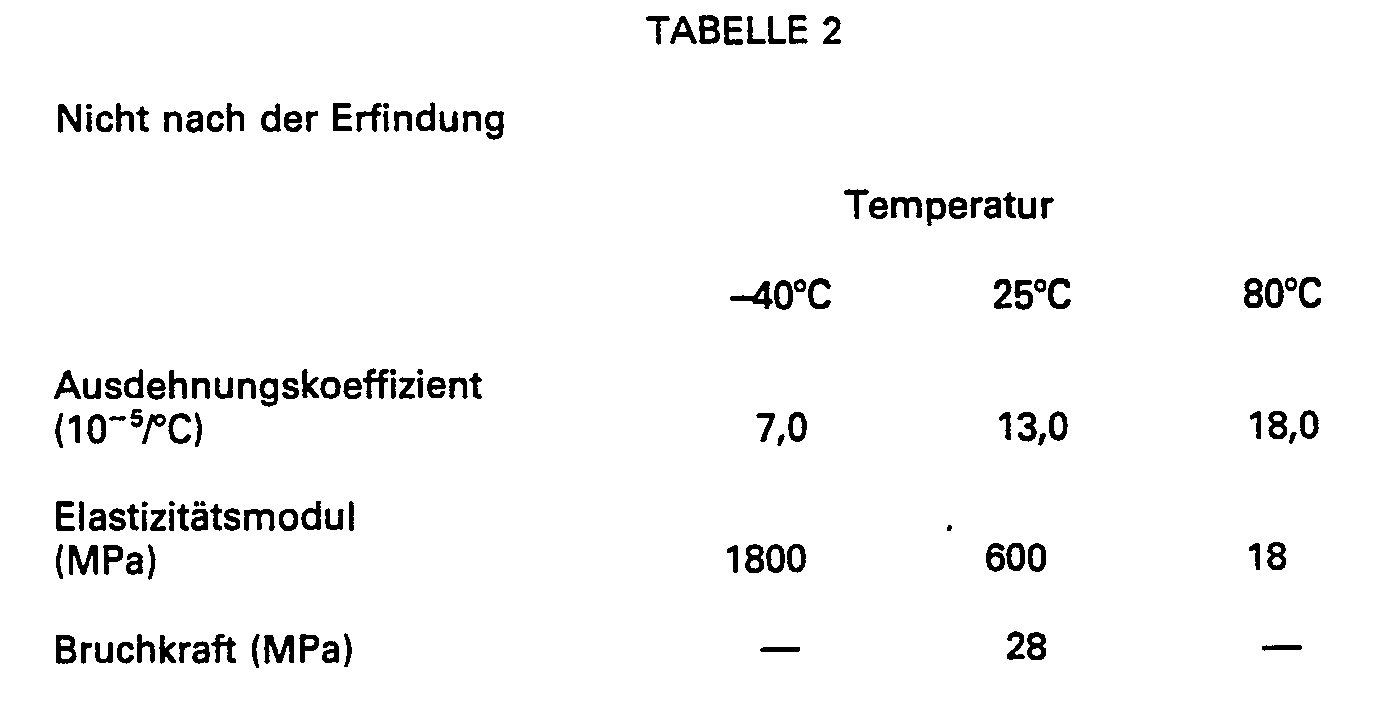
Ein Vergleich mit Tabelle 1 zeigt, dass die Eigenschaften des isotropen Materials mit den Eigenschaften des anisotropen Materials in radialer Richtung vergleichbar sind, dass aber die genannten Eigenschaften wesentlich weniger günstig sind als Eigenschaften des anisotropen Materials in axialer Richtung. Gerade diese letzteren Materialeigenschaften sind bei der Verwendung als Umhüllungsmaterial für optische Fasern von Bedeutung.A comparison with Table 1 shows that the properties of the isotropic material are comparable to the properties of the anisotropic material in the radial direction, but that the properties mentioned are much less favorable than properties of the anisotropic material in the axial direction. It is precisely these latter material properties that are important when used as a covering material for optical fibers.
Fig. 4 zeigt einen schematischen Schnitt durch eine Faserbedeckungsvorrichtung mit einem oberen Teil 10 und einem Bodenteil 11, wobei diese Teile z.B. mittels einer Schraubverbindung miteinander verbunden sind. Der obere Teil 10 weist einen Zuführungskanal 12 auf, durch den eine Glasfaser 13 mit den (in der Figur nicht dargestellten) ggf. bereits vorhandenen Umhüllungsschichten zugeführt werden kann. Der obere Teil 10 und der Bodenteil 11 umschliessen einen Raum 14. Die härtbare Kunststoffzusammensetzung kann durch eine Zuführungsöffnung 15 in dem Bodenteil 11 zugeführt werden und über den Raum 14 und eine ringförmige Düse 16 auf der Glasfaser 13 angebracht werden. Der Durchmesser der ringförmigen Düse 16 ist grösser als der Durchmesser der Glasfaser 13 mit den darauf anzubringenden Schichten. Die Transportgeschwindigkeit der Glasfaser 13 in der Abwärtsrichtung wird derart gross gewählt, dass die flüssige härtbare Kunststoffzusammensetzung einer Dehnungsströmung ausgesetzt wird, and der Stelle, die in der Figur durch den Pfeil 17 bezeichnet ist. In dem Bodenteil 11 befinden sich Kanäle 18 mit einer Zuführungsöffnung 19 und mit einer Abführungsöffnung 20, wodurch beim Betrieb eine Heizflüssigkeit, z.B. Wasser mit einer Temperatur von 80°C, hindurchgeführt werden kann. In dem oberen Teil 10 befindet sich eine Öffnung 21, die mit einer (in der Figur nicht dargestellten) Vakuumpumpe verbunden werden kann, um in dem Raum 22 zwischen der Glasfaser 13 und der zugeführten Kunststoffzusammensetzuhg einen Unterdruck zu erzeugen.Fig. 4 shows a schematic section through a fiber covering device with an
Claims (5)
Applications Claiming Priority (2)
| Application Number | Priority Date | Filing Date | Title |
|---|---|---|---|
| NL8502402 | 1985-09-03 | ||
| NL8502402A NL8502402A (en) | 1985-09-03 | 1985-09-03 | OPTICAL FIBER PROVIDED WITH A PLASTIC COATING, AND METHOD AND APPARATUS FOR MANUFACTURING SUCH OPTICAL FIBER. |
Publications (2)
| Publication Number | Publication Date |
|---|---|
| EP0213680A1 EP0213680A1 (en) | 1987-03-11 |
| EP0213680B1 true EP0213680B1 (en) | 1990-05-09 |
Family
ID=19846495
Family Applications (1)
| Application Number | Title | Priority Date | Filing Date |
|---|---|---|---|
| EP86201482A Expired - Lifetime EP0213680B1 (en) | 1985-09-03 | 1986-08-29 | Optical fibre with a synthetic coating, and process for making such an optical fibre |
Country Status (6)
| Country | Link |
|---|---|
| US (1) | US4733941A (en) |
| EP (1) | EP0213680B1 (en) |
| JP (1) | JPH0830777B2 (en) |
| CA (1) | CA1269261A (en) |
| DE (1) | DE3671005D1 (en) |
| NL (1) | NL8502402A (en) |
Families Citing this family (25)
| Publication number | Priority date | Publication date | Assignee | Title |
|---|---|---|---|---|
| NL8602337A (en) * | 1986-09-16 | 1988-04-18 | Philips Nv | METHOD FOR MANUFACTURING AN OPTICAL FIBER |
| US4854668A (en) * | 1987-04-14 | 1989-08-08 | Siemens Aktiengesellschaft | Light waveguide having three protective layers of plastic material and a method of manufacture |
| US4851165A (en) * | 1987-09-02 | 1989-07-25 | American Telephone And Telegraph Company At&T Bell Laboratories | Methods of and apparatus for coating optical fiber |
| NL8702395A (en) * | 1987-10-08 | 1989-05-01 | Philips Nv | OPTICAL FIBER FITTED WITH A PLASTIC COVER. |
| DE3744465C1 (en) * | 1987-12-23 | 1989-02-09 | Siemens Ag | Device and method for producing the insulation layer of a line |
| JPH0778564B2 (en) * | 1988-03-09 | 1995-08-23 | 日立電線株式会社 | Plastic optical fiber manufacturing method |
| GB8809595D0 (en) * | 1988-04-22 | 1988-05-25 | Bicc Plc | Method & apparatus for making optical fibre member |
| JP2775757B2 (en) * | 1988-07-01 | 1998-07-16 | 東レ株式会社 | Polymer clad quartz optical fiber cord |
| US4848869A (en) * | 1988-08-08 | 1989-07-18 | Corning Incorporated | Method of coating and optical fiber comprising polyimide-silicone block copolymer coating |
| US4950049A (en) * | 1989-02-28 | 1990-08-21 | At&T Bell Laboratories | Stable package of elongated optical fiber strand material |
| US5205890A (en) * | 1989-02-28 | 1993-04-27 | At&T Bell Laboratories | Method for providing stable package of elongated optical fiber with bonded convolutions |
| CA1321671C (en) * | 1989-05-11 | 1993-08-24 | Paul J. Shustack | Ultraviolet radiation-curable coatings for optical fibers and optical fibers coated therewith |
| US5352712A (en) * | 1989-05-11 | 1994-10-04 | Borden, Inc. | Ultraviolet radiation-curable coatings for optical fibers |
| US5536529A (en) * | 1989-05-11 | 1996-07-16 | Borden, Inc. | Ultraviolet radiation-curable coatings for optical fibers and optical fibers coated therewith |
| US4962992A (en) * | 1989-05-15 | 1990-10-16 | At&T Bell Laboratories | Optical transmission media and methods of making same |
| US5104433A (en) * | 1989-05-15 | 1992-04-14 | At&T Bell Laboratories | Method of making optical fiber |
| CA1341128C (en) * | 1989-06-27 | 2000-10-24 | Borden Chemical, Inc. | Optical fiber array |
| DE69017347T2 (en) * | 1989-10-18 | 1995-09-21 | Philips Electronics Nv | Molecularly oriented plastic composition. |
| JPH10505435A (en) * | 1995-06-29 | 1998-05-26 | フィリップス エレクトロニクス ネムローゼ フェンノートシャップ | Polarizing element |
| JPH10508151A (en) * | 1995-08-23 | 1998-08-04 | フィリップス エレクトロニクス ネムローゼ フェンノートシャップ | Flat-panel image display device |
| FR2764994B1 (en) * | 1997-06-19 | 1999-08-06 | Alsthom Cge Alcatel | OPTICAL CONDUCTOR AND OPTICAL CONDUCTOR TAPE |
| CN1247478C (en) | 2000-12-29 | 2006-03-29 | Dsmip财产有限公司 | Non-crystal-forming oligomers for use in radiation-carable fiber optic coatings |
| US7221826B2 (en) * | 2002-10-08 | 2007-05-22 | Tdk Corporation | Spot-size transformer, method of producing spot-size transformer and waveguide-embedded optical circuit using spot-size transformer |
| JP2004170924A (en) * | 2002-11-05 | 2004-06-17 | Tdk Corp | Waveguide embedded optical circuit and optical element used therefor |
| US8178020B2 (en) * | 2007-07-24 | 2012-05-15 | Pascale Industries, Inc. | Multicomponent textile fibers, methods for their production, and products made using them |
Family Cites Families (6)
| Publication number | Priority date | Publication date | Assignee | Title |
|---|---|---|---|---|
| US4127370A (en) * | 1975-05-14 | 1978-11-28 | The Post Office | Apparatus for forming dielectric optical waveguides |
| US3960530A (en) * | 1975-07-28 | 1976-06-01 | Northern Electric Company Limited | Method of coating a glass fiber filament |
| US4482204A (en) * | 1980-02-25 | 1984-11-13 | At&T Bell Laboratories | Ultraviolet absorbers in optical fiber coatings |
| US4502222A (en) * | 1982-12-06 | 1985-03-05 | Michael P. Breston | Shears for cutting sheet metal |
| US4474830A (en) * | 1982-12-29 | 1984-10-02 | At&T Bell Laboratories | Multiple coating of fibers |
| NL8303252A (en) * | 1983-09-22 | 1985-04-16 | Philips Nv | OPTICAL GLASS FIBER WITH A FIRST AND A SECOND COVER. |
-
1985
- 1985-09-03 NL NL8502402A patent/NL8502402A/en not_active Application Discontinuation
-
1986
- 1986-08-28 CA CA000517044A patent/CA1269261A/en not_active Expired - Lifetime
- 1986-08-29 DE DE8686201482T patent/DE3671005D1/en not_active Expired - Lifetime
- 1986-08-29 EP EP86201482A patent/EP0213680B1/en not_active Expired - Lifetime
- 1986-09-01 JP JP61203892A patent/JPH0830777B2/en not_active Expired - Lifetime
- 1986-09-02 US US06/903,008 patent/US4733941A/en not_active Expired - Lifetime
Non-Patent Citations (1)
| Title |
|---|
| Electronic letters, Band 20, Seiten 841,842 (1984) Y. SHUTO et al. * |
Also Published As
| Publication number | Publication date |
|---|---|
| JPS6259911A (en) | 1987-03-16 |
| DE3671005D1 (en) | 1990-06-13 |
| NL8502402A (en) | 1987-04-01 |
| CA1269261A (en) | 1990-05-22 |
| EP0213680A1 (en) | 1987-03-11 |
| JPH0830777B2 (en) | 1996-03-27 |
| US4733941A (en) | 1988-03-29 |
Similar Documents
| Publication | Publication Date | Title |
|---|---|---|
| EP0213680B1 (en) | Optical fibre with a synthetic coating, and process for making such an optical fibre | |
| EP0140415B1 (en) | Optical glass fibre with a double layer coating | |
| EP0167199B1 (en) | Optical-glass fibre with a polymeric coating, and process for making it | |
| EP0151743B1 (en) | Optical transmission element | |
| DE60022957T2 (en) | Process for the production of highly stressed composite parts | |
| EP0155051B1 (en) | Optical glass fibre with a polymer coating and process for making it | |
| DE3106451A1 (en) | MANUFACTURING METHOD FOR AN OPTICAL FIBER WITH A COATING CURED BY UV RADIATION | |
| DE3545089A1 (en) | SINGLE-CORD CABLE FROM A REINFORCED OPTICAL FIBER AND METHOD FOR THE PRODUCTION THEREOF | |
| DE3122235A1 (en) | METHOD FOR PRODUCING FIBER REINFORCED RESIN STRUCTURES | |
| EP0178736A1 (en) | Process for making an optical fibre with a synthetic coating | |
| DE3016009A1 (en) | METHOD FOR PRODUCING FIBER REINFORCED RESIN STRUCTURES | |
| DE69534649T2 (en) | COMPOSITE GLASS LUBRICANTS, METHOD OF USE AND PRODUCTS THEREOF | |
| WO2003054594A2 (en) | Solid core optic fiber and method for the production thereof | |
| EP0260756B1 (en) | Method of manufacturing an optical fibre | |
| DE60101774T2 (en) | Optical fiber coating to increase the micro bending strength | |
| DE69805520T3 (en) | Optical fiber with a jacket and process for its production | |
| EP0287016A2 (en) | Optical waveguide with three plastic protective coatings and method of its manufacture | |
| EP0412242A1 (en) | Optical fiber | |
| DE3814298A1 (en) | OPTICAL FIBER | |
| EP0117594A2 (en) | Method of producing a tubular wave guide and device for carrying out the method | |
| DE4226343C2 (en) | Method and device for producing an optical fiber | |
| EP2176060A2 (en) | Process and apparatus for the production of an elastomeric optical conductor fibre, and optical conductor fibre | |
| EP0469383A1 (en) | Optical transmission element and method for its production | |
| EP0212706B1 (en) | Optical fibre with a plastic coating and curable synthetic resin composition | |
| DE2944073C2 (en) | Fiber optic cable and process for its manufacture |
Legal Events
| Date | Code | Title | Description |
|---|---|---|---|
| PUAI | Public reference made under article 153(3) epc to a published international application that has entered the european phase |
Free format text: ORIGINAL CODE: 0009012 |
|
| AK | Designated contracting states |
Kind code of ref document: A1 Designated state(s): DE FR GB IT NL SE |
|
| 17P | Request for examination filed |
Effective date: 19870702 |
|
| 17Q | First examination report despatched |
Effective date: 19881212 |
|
| GRAA | (expected) grant |
Free format text: ORIGINAL CODE: 0009210 |
|
| AK | Designated contracting states |
Kind code of ref document: B1 Designated state(s): DE FR GB IT NL SE |
|
| REF | Corresponds to: |
Ref document number: 3671005 Country of ref document: DE Date of ref document: 19900613 |
|
| ITF | It: translation for a ep patent filed |
Owner name: ING. C. GREGORJ S.P.A. |
|
| GBT | Gb: translation of ep patent filed (gb section 77(6)(a)/1977) | ||
| ET | Fr: translation filed | ||
| PGFP | Annual fee paid to national office [announced via postgrant information from national office to epo] |
Ref country code: SE Payment date: 19900828 Year of fee payment: 5 |
|
| PGFP | Annual fee paid to national office [announced via postgrant information from national office to epo] |
Ref country code: NL Payment date: 19900831 Year of fee payment: 5 |
|
| PLBE | No opposition filed within time limit |
Free format text: ORIGINAL CODE: 0009261 |
|
| STAA | Information on the status of an ep patent application or granted ep patent |
Free format text: STATUS: NO OPPOSITION FILED WITHIN TIME LIMIT |
|
| 26N | No opposition filed | ||
| PG25 | Lapsed in a contracting state [announced via postgrant information from national office to epo] |
Ref country code: SE Effective date: 19910830 |
|
| PG25 | Lapsed in a contracting state [announced via postgrant information from national office to epo] |
Ref country code: NL Effective date: 19920301 |
|
| NLV4 | Nl: lapsed or anulled due to non-payment of the annual fee | ||
| ITTA | It: last paid annual fee | ||
| EUG | Se: european patent has lapsed |
Ref document number: 86201482.6 Effective date: 19920306 |
|
| ITPR | It: changes in ownership of a european patent |
Owner name: CAMBIO RAGIONE SOCIALE;PHILIPS ELECTRONICS N.V. |
|
| REG | Reference to a national code |
Ref country code: FR Ref legal event code: CD |
|
| REG | Reference to a national code |
Ref country code: GB Ref legal event code: 732E |
|
| REG | Reference to a national code |
Ref country code: FR Ref legal event code: TP |
|
| PGFP | Annual fee paid to national office [announced via postgrant information from national office to epo] |
Ref country code: FR Payment date: 19990604 Year of fee payment: 14 |
|
| PGFP | Annual fee paid to national office [announced via postgrant information from national office to epo] |
Ref country code: GB Payment date: 19990825 Year of fee payment: 14 |
|
| PGFP | Annual fee paid to national office [announced via postgrant information from national office to epo] |
Ref country code: DE Payment date: 19991102 Year of fee payment: 14 |
|
| PG25 | Lapsed in a contracting state [announced via postgrant information from national office to epo] |
Ref country code: GB Free format text: LAPSE BECAUSE OF NON-PAYMENT OF DUE FEES Effective date: 20000829 |
|
| GBPC | Gb: european patent ceased through non-payment of renewal fee |
Effective date: 20000829 |
|
| PG25 | Lapsed in a contracting state [announced via postgrant information from national office to epo] |
Ref country code: FR Free format text: LAPSE BECAUSE OF NON-PAYMENT OF DUE FEES Effective date: 20010430 |
|
| PG25 | Lapsed in a contracting state [announced via postgrant information from national office to epo] |
Ref country code: DE Free format text: LAPSE BECAUSE OF NON-PAYMENT OF DUE FEES Effective date: 20010501 |
|
| REG | Reference to a national code |
Ref country code: FR Ref legal event code: ST |
|
| PG25 | Lapsed in a contracting state [announced via postgrant information from national office to epo] |
Ref country code: IT Free format text: LAPSE BECAUSE OF NON-PAYMENT OF DUE FEES;WARNING: LAPSES OF ITALIAN PATENTS WITH EFFECTIVE DATE BEFORE 2007 MAY HAVE OCCURRED AT ANY TIME BEFORE 2007. THE CORRECT EFFECTIVE DATE MAY BE DIFFERENT FROM THE ONE RECORDED. Effective date: 20050829 |