EP0211460B1 - Procédé de radio-transmission numérique - Google Patents
Procédé de radio-transmission numérique Download PDFInfo
- Publication number
- EP0211460B1 EP0211460B1 EP86201270A EP86201270A EP0211460B1 EP 0211460 B1 EP0211460 B1 EP 0211460B1 EP 86201270 A EP86201270 A EP 86201270A EP 86201270 A EP86201270 A EP 86201270A EP 0211460 B1 EP0211460 B1 EP 0211460B1
- Authority
- EP
- European Patent Office
- Prior art keywords
- division multiplex
- code
- transmission
- frequency
- channels
- Prior art date
- Legal status (The legal status is an assumption and is not a legal conclusion. Google has not performed a legal analysis and makes no representation as to the accuracy of the status listed.)
- Expired - Lifetime
Links
Images


Classifications
-
- H—ELECTRICITY
- H04—ELECTRIC COMMUNICATION TECHNIQUE
- H04W—WIRELESS COMMUNICATION NETWORKS
- H04W88/00—Devices specially adapted for wireless communication networks, e.g. terminals, base stations or access point devices
- H04W88/08—Access point devices
Definitions
- the invention relates to a digital radio transmission system according to the preamble of patent claim 1.
- Three basic methods are known for transmitting messages via a transmission medium (e.g. line, radio link) that is shared by a large number of subscribers, namely the code division multiplex method, the frequency multiplex method and the time division multiplex method.
- a transmission medium e.g. line, radio link
- the various messages carried over a common transmission medium are modulated onto a carrier by base modulation, and the resulting narrow-band signal compared to the channel bandwidth is spectrally spread to the channel bandwidth by means of a code word characterizing the receiver.
- the signal is not recognized by temporal or frequency selection, but by means of the spectral coding.
- the multiplicity of spectrally coded messages superimposed in the code division multiplex channel are selected in the receiver on the basis of the code word assigned to them.
- the total bandwidth available for message transmission is divided into narrow frequency bands, each of which corresponds to a message transmission channel.
- the subscriber has one for the duration of the radio transmission narrow frequency band available.
- the entire bandwidth of a single radio channel is available to each subscriber, which the subscriber may only use for short periods of time.
- the characters or character strings of different subscribers are interleaved and are transmitted at a correspondingly higher bit rate in the single radio channel, the time channel assigned to each subscriber being repeated periodically with the frame period.
- An incoherent carrier demodulation is used for the code word synchronization.
- a code generator successively generates one of the nine different codes that identify the fixed land stations. After this code is synchronized with the received signal, the IF signal is multiplied by it, whereby the broad spectrum is transformed into the message bandwidth.
- the received message can then be recovered using a DPSK demodulator, for example.
- a separate code pattern with a length of 15 bits, for example, is used for the synchronization, which precedes the message.
- time channels for voice and / or data transmission (communication channel TCH)
- one bit is consecutively -Transmission to determine the bit clock (synchronous), a frame synchronization word (header) and the bit sequence of the message itself transmitted.
- the time channels for message transmission (3x20 TCH) are with organization channels (3 CCH) to a time-division multiplex frame with the duration 31.5 msec ..
- CCH organization channels
- adaptive delta modulation can be used for analog-to-digital conversion.
- the message characters (bits) that are created in this way are overlaid with a code in the transmitter. It has proven to be advantageous the individual message characters together in blocks of four bits each and grasp the resulting blocks with an orthogonal alphabet.
- the spreading factor used here is a compromise in order to combine the advantages of band spreading with the demand for frequency economy.
- a message transmission method has been proposed DE-A-3 447 107 in accordance with European application EP-A-0 188 836, in which a different modulation method is used in the forward and backward direction of the message transmission channel.
- the mobile radio stations access one of a large number of message channels for message transmission. In the direction from the fixed radio station to the mobile radio stations assigned to it, each message channel is spread by spread modulation.
- the spread news channels are superimposed on one another and the broadband sum signal thus obtained is transmitted in a common frequency band.
- the messages are transmitted in separate, narrowband frequency channels.
- the spread modulation used is selected by the fixed radio station and communicated to the mobile radio station when the connection is established.
- spread modulation common to all mobile radio stations is used in the direction from the stationary radio station to the mobile radio stations.
- Narrow-band receivers are arranged in the fixed radio stations and can be switched over to several frequency channels during operation.
- the number of transmitting frequencies that can be switched in the mobile radio station is less than the number of receiving frequencies that can be switched in the fixed radio station. For example, a switchover to 1,000 frequencies can be carried out in the fixed radio station and a switchover to 40 frequencies in the mobile radio station.
- the reception frequencies used there are managed in each fixed radio station.
- the connection concerned in the direction from the mobile radio station to the fixed radio station, is switched to another undisturbed frequency channel on which both the fixed radio station and the mobile radio station can switch.
- the receiving device in the fixed radio station to the wire network of the public telephony system remains involved in the connection.
- the invention has for its object to make the formation of message channels in a digital radio transmission system such that an adaptation to inhomogeneous traffic densities and an inexpensive implementation for the transmitter in the fixed radio station and the receiver in the mobile radio station is achieved.
- the digital radio transmission system according to the invention can be adapted well to inhomogeneous traffic densities. This takes place on the one hand through the formation of large radio cells at low traffic densities and small radio cells at high traffic densities and on the other hand through the occupancy of several frequency bands within a radio cell with high traffic density.
- This frequency division multiplex method channel sets
- radio cells with a very high traffic density several channel sets (message channels with the same code set) can be operated using the frequency division multiplex method, so that the formation of very small cells can be avoided.
- time-division multiplex method uses the time-division multiplex method to create additional message channels in each code level, so that the transmission capacity in the digital radio transmission system can be further increased. As a result, transmission devices in the fixed radio station can be saved in comparison to a pure frequency division multiplex system.
- fixed radio stations BS are spatially arranged according to a cell system.
- a number of radio transmission channels are assigned to each fixed radio station BS, via which messages are transmitted to mobile radio stations MS.
- Different combinations of multiplexing methods are used in the two transmission directions for the bundling of message channels.
- the message to be sent (voice or data) is inserted into the message channels using code division multiplex, time division multiplex and frequency division multiplex methods.
- a TDM multiplexer 3 a code word generator 5 and a synthesizer 9 are arranged in the fixed radio station BS (cf. FIG. 4).
- the separation of the message channels of the received digital signal takes place in the mobile radio station MS using the code division multiplex, time division multiplex and frequency division multiplex method.
- a synthesizer 19, correlators 24 and 25 and a TDM demultiplexer 31 (cf. FIG.
- the mobile radio station MS For the direction of transmission from the mobile radio stations MS to the fixed radio station BS, the message transmission takes place in separate, narrowband frequency channels.
- the multiplexing for the direction of transmission from the fixed radio station BS to the mobile radio stations MS is described and explained in more detail below.
- a fixed radio station BS has, for example, at least one channel set, consisting of 32 message channels.
- the individual message channels for the various mobile radio stations MS in a channel set are separated from one another by different spreading code words (CDMA) and / or different time slots (TDMA).
- CDMA spreading code words
- TDMA time slots
- 1 shows three such channel sets, with channel sets 1 and 2 belonging to the same radio cell and channel set 3 belonging to an adjacent radio cell in the example shown.
- the identification of the individual message channels (channel identifier) is illustrated in FIG. 1 by the sequence of numbers with three digits. The first digit means the number of the respective time slot, the second digit the code word used in each case and the third digit the respective number of the carrier frequency used.
- the bundling of the message channels in the direction of transmission from the fixed radio station BS to the mobile radio stations MS takes place through the succession of the time division multiplex, code division multiplex and finally frequency division multiplex method.
- This preferred sequence facilitates the implementation of the transmitting and receiving devices of the digital radio transmission system.
- a channel set is built up e.g. in that several time slots, each of which contains the information for one subscriber in each case, are combined to form a time-division multiplex frame.
- the time-division multiplex frame comprises four time slots, e.g. News channel 1.1.1 to 4.1.1.
- time-division multiplex frames are then spread with appropriately selected code words, which allow a plurality of time-division multiplex frames to be transmitted simultaneously and with the same carrier frequency.
- the spreading of each of these time-division multiplex frames takes place with a code word, which in this channel set is assigned only to this special time-division multiplex frame others that the information in the time slots of a time-division multiplex frame is spread with the same code word.
- a channel set contains 8 different time-division multiplex frames with 4 time channels each, so a total of 32 message channels per channel set.
- the 8 individual spread codes have a spread of 31, i.e. a length of 31 chips.
- All code multiplex channels are transmitted by the transmitter of the fixed radio station BS with the same power and synchronously.
- the four symbols can be represented, for example, by two antipodal code words
- two bits of the useful signal can be combined into one symbol. This reduces the symbol rate by half compared to the bit rate of the baseband.
- 32 message channels of, for example, 16 kbit / s can be transmitted, which are modulated onto a common RF carrier after code spreading.
- the transmission of 32 message channels e.g. a bandwidth of 1.25 MHz.
- the time grading and thus the number of message channels per spreading code level depends on the bit rate required for each message transmission channel.
- a change in the spreading code has only little influence on the receiving device, since it has programmable correlators which are reset from connection to connection on the instruction of the fixed radio station BS.
- An organizational channel can be provided for the transmission of such setting information and for the separation of the individual time channels (message channels) in the time-division multiplex frame.
- the received digital signal is mixed into the baseband in the receiver of the mobile radio station MS.
- the information is recovered by correlation with the code word used for this message channel, which is also communicated to the mobile radio station when the connection is established.
- the separation of the message channels of the received digital signal takes place in the reverse order, ie demultiplexing with regard to frequency, code and time, as in the bundling of the message channels in the fixed radio station BS.
- the chip duration is 0.806 ns and the chip rate is 1.24 Mcps. This also means that the chip duration is short enough to allow sufficient resolution and utilization of the multi-paths and to avoid fading influences as far as possible.
- At least one organizational channel is provided for each channel set, on which the mobile radio stations MS access the connection and via which the connection and some special services are handled.
- the mobile radio stations MS know the frequency position of the possible channel sets, the corresponding time channel and the code words for the organizational channels assigned within the digital radio transmission system.
- the mobile radio station MS can search for the suitable organizational channel and there all for the access (eg frequency of the narrowband (reverse) direction from mobile radio stations MS to the fixed radio station BS of the respective organizational channel) and for the establishment of the connection (eg time channel and code word for the direction from the fixed radio station BS to the mobile radio station MS, and the frequency for the narrowband direction from the mobile radio station MS to the fixed radio station BS).
- the channel sets 1 and 2 are assigned to the fixed radio station BS1.
- the same code words can be used for the two channel sets assigned to the fixed radio station BS1 because they are transmitted on different carrier frequencies.
- the message channels are separated from adjacent fixed radio stations BS either using the frequency division multiplex method (different RF carriers for the channel sets used in these fixed radio stations BS), using the code multiplex method (different code word sets for the channel sets used) or by combinations of these two multiplex methods.
- the channel set 3 of the fixed radio station BS2 differs from the two channel sets 1 and 2 of the fixed radio station BS1 both in the code word set (2nd digit of the channel identifier) and by the RF carrier frequency used (3rd digit the channel identifier).
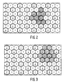
- a channel set (RF carrier and / or code word set) used in this cell can be repeated at sufficiently large spatial distances (determined by co-channel interference occurring) from one cell to another (cf. FIGS. 2 and 3).
- the possibility of using the same RF carrier frequency in the remote radio cell and / or using different code word sets leads to additional flexibility and freedom in reuse planning and facilitates the introduction of small cell structures.
- the method of dynamic, flexible channel allocation can be used, a smaller "effective" co-channel repetition distance and thus a larger network capacity being able to be achieved.
- 2 and 3 show the frequency allocation in homogeneous networks (or homogeneous subnetworks), the radio cells being combined into cell groups (clusters) consisting of a number of radio cells. Different channel sets are used in the different cells of a cell group. In this case, several channel sets can be assigned to the fixed radio station BS within a radio cell. The distribution of the channel sets in a cell group is repeated periodically in space.
- a certain co-channel repetition distance is associated with the size of the cell group, the co-channel repetition distance and thus also the size of the cell group to be selected in the network design such that certain requirements are met for freedom from interference in the network.
- a total bandwidth of 25 MHz available in the digital radio transmission system for example, 20 channel sets (each with 32 message channels) with a transmission bandwidth of approximately 1.25 MHz can be formed.
- adjacent radio cells are separated from one another by different carrier frequencies and co-channel cells by different code words, then in the broadband direction, ie in the direction from the fixed radio station BS to the mobile radio stations MS cell groups with, for example, three or four radio cells per cell group (see FIGS. 2 and 3).
- FIGS. 2 and 3 illustrates the broadband direction from the fixed radio station BS to the mobile radio stations MS cell groups with, for example, three or four radio cells per cell group.
- the numbers 1 to 3 denote different carrier frequencies and the letters A to D different code sets.
- the numbers 1 to 3 denote different carrier frequencies and the letters A to D different code sets.
- a narrowband transmission with frequency channels in a 25 KHz grid can be provided.
- the frequency division is not fixed in the radio cells themselves, rather the frequencies are freely assigned by the fixed radio station BS.
- Fig. 4 shows the block diagram of the transmitting part of the fixed radio station BS.
- the data / voice stream transmitted in the baseband is composed as follows.
- the digitized speech of each individual channel is first transcoded in a PCM transcoder 1 to the transmission method required for radio transmission with a correspondingly lower bit rate.
- a data source can be connected to the interface BB.
- a channel encoder 2 connected to the data source or transcoder 1
- a special channel coding is added to protect significant bits against transmission errors on the transmission channel. These Channel coding can vary depending on the service being transmitted.
- a multiplexer 3 connected to the channel encoder 2, the connection-accompanying signaling and the synchronization information originating from a synchronization circuit 4 are added to the data stream.
- the TDM signal (T Time Division ultiplex signal) at the output of TDM multiplexer 3 thus contains in the illustrated in Fig. 4 embodiment, four voice / data channels, one accompanying the connection signaling channel (for a TDM channel bundle) and for the synchronization in the mobile radio stations MS required synchronization bits.
- the synchronization bits are superimposed on the TDM signal, as suggested in P 35 11 430.4.
- the TDM signal at the output of the multiplexer 3 is multiplied by the respective code words generated by code generators 5, two bits being combined to form a symbol and spreading with the desired code.
- the code generator 5 is connected to a control device 15 and, at the command of the control device 15, inserts synchronization symbols instead of data symbols into the continuous data stream occurring at the output of the multiplexer 3.
- a modulation method adapted to the properties of the radio transmission channel is applied to the spread signal, for example the phase of a carrier signal originating from an oscillator 6 is then keyed with the spread signal, as a result of which a BPSK (binary.), which is linked to the information and the code word, is modulated at a low intermediate frequency Phase Shift Keying) signal is generated.
- the modulated CDM signal is fed to a summer 7, the output of which is connected to a bandpass filter 8. Eight of these modulated CDM signals, after addition and bandpass filtering, form a multi-level amplitude signal that is finally converted to the final frequency.
- a synthesizer 9 is provided as a mixed oscillator, which can be switched with corresponding stages within the frequency range of the digital radio transmission system.
- the synthesizer 9 is designed only for the few possible frequencies of the FDM stage (Frequency Division ultiplex M-stage).
- the CDM signal is mixed with the corresponding frequency supplied by the synthesizer 9 in a device 10 which is connected to a bandpass filter 11.
- the output of the bandpass filter 11 is connected to a power amplifier 12 and the filtered and amplified transmission signal reaches the antenna 14 via a transmitter coupler 13.
- the transmitter coupler 13 is completely eliminated.
- the channel and code generator setting, the correct selection of the channel coding and the insertion of messages into the organizational data stream are carried out by means of the control device 15 arranged in the fixed radio station BS.
- the selected radio transmission channel can be a TDM channel in a CDM level (cf. P 35 11 430.4).
- Fig. 5 shows the block diagram of the receiving part of the mobile radio station MS.
- the signal received by a common transmitting / receiving antenna 16 passes through a reception filter of a duplexer 17 to the input stage 18 of the receiver.
- the requirements for the reception filter of the duplexer 17 are relatively low, so that there is also an inexpensive solution for mobile radio stations MS with low service requirements, for example simple data radio.
- the signal is amplified in the input stage 18 and then mixed with an synthesizer frequency originating from a synthesizer 19 to an intermediate frequency.
- the intermediate frequency signal is fed to an IF section 20, in which the signal is further amplified and filtered.
- a simple synthesizer can also be used for the synthesizer 19, as for the synthesizer 9 of the fixed radio station BS, which can be implemented inexpensively.
- Filters are arranged in the ZF part 20, which serve the adjacent channel selection to differentiate from adjacent broadband channels or to suppress mixed products. The actual noise filtering takes place in correlators 23 to 25.
- An amplitude control circuit 21 is connected to the IF part 20, which raises the output signal of the IF part 20 to a sufficient level for driving the subsequent circuits and prevents possible overdriving of these circuits.
- the amplitude control circuit 21 compensates for different radio field attenuations and level fluctuations due to shadowing, so that linear processing can be carried out in the subsequent devices of the mobile radio station MS.
- the control time constant of the amplitude control circuit 21 is essentially determined by these shadows.
- the IF signal which is regulated in terms of power, at the output of the amplitude control circuit 21 is converted into the baseband in a demodulator 22 connected to the latter.
- This can be done, for example, when using a BPSK modulation on the principle of a Costass loop, so that frequency and phase are also taken into account.
- Ambiguities by integer multiples of 180 ° can be recognized and compensated accordingly based on the polarity of the received synchronous words (cf. P 35 11 430.4).
- the demodulator 22 With the demodulator 22 are three correlators 23, 24 and 25 connected, which are set by a control device 26 to the currently valid codes 1 and 2 and to a synchronous code valid for the entire channel bundle in the radio zone.
- the received organizational data stream is evaluated by means of the control device 26 by reading out the data of the services desired by the subscriber and the data for the radio transmission channels provided for the type of device, selecting a radio transmission channel identified as free in the organizational data stream and also selectable in the mobile radio station MS, and then an access signal is sent on this selected radio transmission channel to the fixed radio station BS.
- the output signal of the correlators 23 to 25 is used on the one hand to derive the symbol clock, frame clock and bit clock and on the other hand this is used to measure the currently valid multipath profile. Since a uniform synchronizing code with a correspondingly higher level is emitted in the entire channel bundle at the same time (cf. P35 11 430.4), this results in reliable synchronization detection and measurement of the multi-way profile.
- the outputs of the correlators 24 and 25 are connected to sampling circuits 27, 28 which sample the output signals of the correlators 24 and 25 and feed the respective result to a decision stage 29.
- the results of the scans running in synchronization with the echoes of the multipath propagation are weighted in decision stage 29 in proportion to the amplitude of the echoes (by means of a device 30).
- Decision stage 29 has the task of estimating the code sent and the polarity of the code. The estimated value thus allows the selection of the one sent with the greatest probability Symbol.
- the output signal is fed to a TDM demultiplexer 31 connected to decision stage 29.
- the demultiplexer 31 is connected to a channel decoder 32 at whose output the transmitted data stream is available again.
- the digital speech signal is decoded in a speech decoder 33, fed to a D / A converter and a loudspeaker connected to it.
- the data occurring at the output of the channel decoder 32 can be immediately e.g. displayed or printed out.
Claims (6)
- Procédé de transmission pour un système de transmission radio numérique comportant des postes de radio fixes (BS) installés dans un réseau cellulaire et une pluralité de postes de radio mobiles (MS) indépendants les uns des autres, qui, pour la transmission de messages, accèdent à l'un d'une pluralité de canaux à messages, caractérisé en ce que, dans les deux sens de transmission, on utilise des combinaisons de multiplexages différentes pour le groupage de canaux à messages, étant entendu que, pour le sens de transmission allant du poste de radio fixe (BS) vers les postes de radio mobiles (MS), dans le poste de radio fixe (BS), le message à émettre est introduit dans les canaux à messages (identification de canal X.Y.Z) par application de la combinaison du multiplexage codé, du multiplexage temporel et du multiplexage fréquentiel (multiplexeur TDM 3, générateur de mots de code 5, synthétiseur 9) et que, dans le poste de radio mobile (MS), la séparation des canaux à messages du signal numérique reçu s'effectue par application du multiplexage codé, du multiplexage temporel et du multiplexage fréquentiel (synthétiseur 19, corrélateurs 24 et 25, démultiplexeur TDM 31).
- Procédé de transmission suivant la revendication 1, caractérisé en ce que, pour le sens de transmission allant des postes de radio mobiles (MS) vers le poste de radio fixe (BS), la transmission des messages s'effectue dans des canaux de fréquences à bande étroite séparés les uns des autres ou dans des canaux temporels ou dans des plans de codes ou leurs combinaisons séparés l'un de l'autre.
- Procédé de transmission suivant la revendication 1, caractérisé en ce que, dans le poste de radio fixe (BS), le groupage des canaux à messages est effectué dans l'ordre multiplexage temporel, multiplexage codé et multiplexage fréquentiel, tandis que, dans le poste de radio mobile (MS), la séparation des canaux à messages est effectuée dans l'ordre inverse.
- Procédé de transmission suivant la revendication 1, caractérisé en ce que, dans le cas de postes de radio fixes (BS) à demande de capacité relativement faible, le groupage de canaux à messages est effectué à l'intérieur d'une cellule radio par application du multiplexage codé et du multiplexage temporel.
- Procédé de transmission suivant la revendication 1, caractérisé en ce que, dans le cas de postes de radio fixes (BS) à demande de capacité relativement très faible, le groupage des canaux à messages à l'intérieur d'une cellule radio ne peut être effectué que par application du multiplexage temporel.
- Procédé de transmission suivant la revendication 1, caractérisé en ce que, dans le poste de radio fixe (BS), des combinaisons quelconques de canaux à multiplexage codé et de canaux à multiplexage temporel sont converties sur une fréquence porteuse.
Priority Applications (1)
| Application Number | Priority Date | Filing Date | Title |
|---|---|---|---|
| AT86201270T ATE77191T1 (de) | 1985-07-31 | 1986-07-21 | Digitales funkuebertragungsverfahren. |
Applications Claiming Priority (2)
| Application Number | Priority Date | Filing Date | Title |
|---|---|---|---|
| DE3527331 | 1985-07-31 | ||
| DE19853527331 DE3527331A1 (de) | 1985-07-31 | 1985-07-31 | Digitales funkuebertragungssystem |
Publications (3)
| Publication Number | Publication Date |
|---|---|
| EP0211460A2 EP0211460A2 (fr) | 1987-02-25 |
| EP0211460A3 EP0211460A3 (en) | 1989-03-15 |
| EP0211460B1 true EP0211460B1 (fr) | 1992-06-10 |
Family
ID=6277205
Family Applications (1)
| Application Number | Title | Priority Date | Filing Date |
|---|---|---|---|
| EP86201270A Expired - Lifetime EP0211460B1 (fr) | 1985-07-31 | 1986-07-21 | Procédé de radio-transmission numérique |
Country Status (10)
| Country | Link |
|---|---|
| US (1) | US4799252A (fr) |
| EP (1) | EP0211460B1 (fr) |
| JP (1) | JPS6335025A (fr) |
| AT (1) | ATE77191T1 (fr) |
| AU (1) | AU591691B2 (fr) |
| CA (1) | CA1280228C (fr) |
| DE (2) | DE3527331A1 (fr) |
| DK (1) | DK358086A (fr) |
| FI (1) | FI82339C (fr) |
| NO (1) | NO863040L (fr) |
Cited By (1)
| Publication number | Priority date | Publication date | Assignee | Title |
|---|---|---|---|---|
| US6421368B1 (en) | 1991-06-03 | 2002-07-16 | Xircom Wireless, Inc. | Spread spectrum wireless communication system |
Families Citing this family (66)
| Publication number | Priority date | Publication date | Assignee | Title |
|---|---|---|---|---|
| FR2625389B1 (fr) * | 1987-12-23 | 1990-05-04 | Trt Telecom Radio Electr | Systeme radioelectrique pour permettre l'echange d'informations entre un ensemble de stations |
| JPH0622345B2 (ja) * | 1988-01-14 | 1994-03-23 | 東京電力株式会社 | 移動体通信方式 |
| US4866710A (en) * | 1988-02-22 | 1989-09-12 | Motorola, Inc. | Reuse groups for scan monitoring in digital cellular systems |
| US5185739A (en) * | 1990-02-27 | 1993-02-09 | Motorola, Inc. | Time-allocation of radio carriers |
| US5199031A (en) * | 1990-08-31 | 1993-03-30 | Telefonaktiebolaget L M Ericsson | Method and system for uniquely identifying control channel time slots |
| US5134615A (en) * | 1990-10-05 | 1992-07-28 | Motorola, Inc. | Frequency agile tdma communications system |
| US5506864A (en) * | 1990-12-05 | 1996-04-09 | Interdigital Technology Corporation | CDMA communications and geolocation system and method |
| US5263045A (en) * | 1990-12-05 | 1993-11-16 | Interdigital Technology Corporation | Spread spectrum conference call system and method |
| US7020125B2 (en) * | 1990-12-05 | 2006-03-28 | Interdigital Technology Corporation | Broadband CDMA overlay system and method |
| US5193101A (en) * | 1991-02-04 | 1993-03-09 | Motorola, Inc. | On-site system frequency sharing with trunking systems using spread spectrum |
| CA2043127C (fr) * | 1991-05-23 | 1996-05-07 | Martin Handforth | Systeme de gestion de zones de communication sans fil |
| US5195090A (en) * | 1991-07-09 | 1993-03-16 | At&T Bell Laboratories | Wireless access telephone-to-telephone network interface architecture |
| US5247702A (en) * | 1991-11-08 | 1993-09-21 | Teknekron Communications Systems, Inc. | Method and an apparatus for establishing a wireless communication link between a base unit and a remote unit |
| GB9201879D0 (en) * | 1992-01-29 | 1992-03-18 | Millicom Holdings Uk Ltd | Communication system |
| SE9200607D0 (sv) * | 1992-02-28 | 1992-02-28 | Ericsson Telefon Ab L M | Communication methods and mean in a tdma cellular mobile radio system |
| DE4210305A1 (de) * | 1992-03-30 | 1993-10-07 | Sel Alcatel Ag | Verfahren, Sender und Empfänger zur Informationsdatenübertragung mit veränderlichem Verkehrsaufkommen und Leitstation zur Koordinierung mehrerer solcher Sender und Empfänger |
| GB9209027D0 (en) * | 1992-04-25 | 1992-06-17 | British Aerospace | Multi purpose digital signal regenerative processing apparatus |
| FI97838C (fi) * | 1992-05-06 | 1997-02-25 | Nokia Telecommunications Oy | Solukkoverkkojärjestelmä |
| DE4227990C2 (de) * | 1992-08-21 | 2001-10-18 | Cell Gmbh Q | Funkübertragungsverfahren mittels einer ortsfesten Basisstation und einer Vielzahl voneinander unabhängiger ortsfester Basisstationen |
| EP0620658B1 (fr) * | 1992-11-04 | 2001-12-19 | Ntt Mobile Communications Network Inc. | Systeme de communication mobile a acces multiple par difference de code |
| CA2105710A1 (fr) * | 1992-11-12 | 1994-05-13 | Raymond Joseph Leopold | Reseau de systemes de communication hierarchiques et methode connexe |
| MX9307243A (es) * | 1992-11-24 | 1994-05-31 | Ericsson Telefon Ab L M | Reintento analogico. |
| FI925472A (fi) * | 1992-12-01 | 1994-06-02 | Nokia Mobile Phones Ltd | Tiedonsiirtomenetelmä sekä -järjestelmä |
| DE4243026C2 (de) * | 1992-12-18 | 1994-10-13 | Grundig Emv | Funkalarmanlage mit asynchroner Übermittlung von Meldungen über Zeitkanäle unterschiedlicher Periodendauern |
| DE4242973C2 (de) * | 1992-12-18 | 1995-01-05 | Grundig Emv | Funkalarmanlage mit einer Vielzahl von nach dem Code-Multiplexverfahren gebildeten Nachrichtenkanälen |
| JPH0754991B2 (ja) * | 1993-01-21 | 1995-06-07 | 日本電気株式会社 | ディジタル移動無線通信方式 |
| DE69428492T2 (de) * | 1993-06-04 | 2002-05-23 | Motorola Inc | Verfahren und vorrichtung zum dynamischen einstellen einer maximalen zahl von teilnehmern auf einem physikalischen kanal |
| FI933129A0 (fi) * | 1993-07-08 | 1993-07-08 | Nokia Mobile Phones Ltd | Dataoeverfoeringsfoerfarande foer ett digitalt cellulaert mobiltelefonsystem och ett digitalt cellulaert mobiltelefonsystem |
| US5493563A (en) * | 1993-07-26 | 1996-02-20 | Motorola, Inc. | Method and apparatus for mobile assisted handoff in a communication system |
| DE4329010A1 (de) * | 1993-08-28 | 1995-03-02 | Sel Alcatel Ag | Funksystem |
| US5574750A (en) * | 1993-09-14 | 1996-11-12 | Pacific Communication Sciences, Inc. | Methods and apparatus for detecting a cellular digital packet data (CDPD) carrier |
| US5854808A (en) * | 1993-09-14 | 1998-12-29 | Pacific Communication Sciences | Methods and apparatus for detecting the presence of a prescribed signal in a channel of a communications system |
| JP3003839B2 (ja) * | 1993-11-08 | 2000-01-31 | エヌ・ティ・ティ移動通信網株式会社 | Cdma通信方法および装置 |
| US5586150A (en) * | 1993-11-24 | 1996-12-17 | Rajupandaram K. Balasubramaniam | Method and apparatus for symbol synchronization in multi-level digital FM radio |
| JP2636712B2 (ja) * | 1993-12-08 | 1997-07-30 | 日本電気株式会社 | 移動通信装置 |
| US6018528A (en) * | 1994-04-28 | 2000-01-25 | At&T Corp | System and method for optimizing spectral efficiency using time-frequency-code slicing |
| US5610906A (en) * | 1994-06-29 | 1997-03-11 | Interdigital Technology Corporation | Spread-spectrum changeable base station |
| US5614914A (en) * | 1994-09-06 | 1997-03-25 | Interdigital Technology Corporation | Wireless telephone distribution system with time and space diversity transmission for determining receiver location |
| JP3215018B2 (ja) * | 1994-09-09 | 2001-10-02 | 三菱電機株式会社 | 移動通信システム |
| US6334219B1 (en) * | 1994-09-26 | 2001-12-25 | Adc Telecommunications Inc. | Channel selection for a hybrid fiber coax network |
| US5701585A (en) * | 1994-12-12 | 1997-12-23 | Telefonaktiebolaget Lm Ericsson | Mobile assisted handoff |
| US5625872A (en) * | 1994-12-22 | 1997-04-29 | Telefonaktiebolaget Lm Ericsson | Method and system for delayed transmission of fast associated control channel messages on a voice channel |
| US7280564B1 (en) | 1995-02-06 | 2007-10-09 | Adc Telecommunications, Inc. | Synchronization techniques in multipoint-to-point communication using orthgonal frequency division multiplexing |
| USRE42236E1 (en) | 1995-02-06 | 2011-03-22 | Adc Telecommunications, Inc. | Multiuse subcarriers in multipoint-to-point communication using orthogonal frequency division multiplexing |
| US6132306A (en) * | 1995-09-06 | 2000-10-17 | Cisco Systems, Inc. | Cellular communication system with dedicated repeater channels |
| US5793757A (en) * | 1996-02-13 | 1998-08-11 | Telefonaktiebolaget L M Ericsson (Publ) | Telecommunication network having time orthogonal wideband and narrowband sytems |
| FR2750281B1 (fr) * | 1996-06-19 | 1998-07-31 | Alcatel Espace | Unite d'interface pour reseau de radiocommunications avec les mobiles |
| GB2315388B (en) * | 1996-07-17 | 2000-11-22 | Nokia Mobile Phones Ltd | Mobile communications |
| GB2320661B (en) * | 1996-12-20 | 2001-10-03 | Dsc Telecom Lp | Processing data transmitted and received over a wireless link connecting a central terminal and a subscriber terminal of a wireless telecommunications system |
| DE19700303B4 (de) | 1997-01-08 | 2005-11-03 | Deutsches Zentrum für Luft- und Raumfahrt e.V. | Funkübertragungsverfahren für digitale Multimediatensignale zwischen Teilnehmerstationen in einem lokalen Netz |
| FI970772A (fi) * | 1997-02-24 | 1998-08-25 | Nokia Telecommunications Oy | Kanava-allokointi radiokaistalla |
| JP3308549B2 (ja) | 1997-06-16 | 2002-07-29 | 三菱電機株式会社 | 移動通信システム |
| JP3985299B2 (ja) * | 1997-07-14 | 2007-10-03 | 三菱電機株式会社 | 移動通信システム |
| KR20010031496A (ko) * | 1997-10-27 | 2001-04-16 | 칼 하인쯔 호르닝어 | 무선 통신 시스템 및 제어 장치 |
| AU1555299A (en) * | 1997-10-29 | 1999-05-17 | Siemens Aktiengesellschaft | Transmission/reception process and device and radio communications system for data transmission |
| JP3629136B2 (ja) * | 1998-02-27 | 2005-03-16 | 富士通株式会社 | 複数モード通信装置 |
| JP3093740B2 (ja) * | 1998-12-09 | 2000-10-03 | 日本電気株式会社 | Cdma移動通信システムにおける無線チャネル多重通信方式 |
| US6370160B1 (en) * | 1998-12-29 | 2002-04-09 | Thomson Licensing S. A. | Base to handset epoch synchronization in multi-line wireless telephone |
| EP1164719A4 (fr) * | 2000-01-04 | 2004-12-08 | Mitsubishi Electric Corp | Telephone cellulaire |
| AU5252101A (en) * | 2000-04-28 | 2001-11-12 | Hi-G-Tek Ltd. | Apparatus and methods for cellular communication |
| US7173921B1 (en) | 2000-10-11 | 2007-02-06 | Aperto Networks, Inc. | Protocol for allocating upstream slots over a link in a point-to-multipoint communication system |
| US6690936B1 (en) * | 2000-10-31 | 2004-02-10 | Telefonaktiebolaget Lm Ericsson (Publ) | Air-interface efficiency in wireless communication systems |
| EP1217841A2 (fr) * | 2000-11-27 | 2002-06-26 | Media Glue Corporation | Système, dispositif, méthode et produit de programme d'ordinateur pour la séparation et l'assemblage de trains de bits |
| US7277411B2 (en) * | 2002-08-21 | 2007-10-02 | D.S.P. Group Ltd. | Method and system for transmitting and receiving data in a TDMA frequency hopping system utilizing frequency diversity |
| US20060237384A1 (en) * | 2005-04-20 | 2006-10-26 | Eric Neumann | Track unit with removable partitions |
| JP4900192B2 (ja) * | 2007-10-22 | 2012-03-21 | 沖電気工業株式会社 | 符号分割多重送受信装置及び符号分割多重送受信方法 |
Family Cites Families (10)
| Publication number | Priority date | Publication date | Assignee | Title |
|---|---|---|---|---|
| JPS5154714A (en) * | 1974-10-16 | 1976-05-14 | Nippon Telegraph & Telephone | Tajuonseidensohoshiki |
| US4171464A (en) * | 1977-06-27 | 1979-10-16 | The United State of America as represented by the U. S. Department of Energy | High specific heat superconducting composite |
| US4301530A (en) * | 1978-12-18 | 1981-11-17 | The United States Of America As Represented By The Secretary Of The Army | Orthogonal spread spectrum time division multiple accessing mobile subscriber access system |
| US4215244A (en) * | 1978-12-18 | 1980-07-29 | The United States Of America As Represented By The Secretary Of The Army | Self-adaptive mobile subscriber access system employing time division multiple accessing |
| US4237551A (en) * | 1978-12-22 | 1980-12-02 | Granger Associates | Transmultiplexer |
| JPS5715541A (en) * | 1980-07-01 | 1982-01-26 | Matsushita Electric Ind Co Ltd | Radio communication system |
| EP0064686B1 (fr) * | 1981-05-07 | 1985-07-31 | Alcatel N.V. | Système de transmission de messages |
| US4514853A (en) * | 1982-12-13 | 1985-04-30 | The United States Of America As Represented By The Secretary Of The Army | Multiplexed noise code generator utilizing transposed codes |
| DE3447107A1 (de) * | 1984-12-22 | 1986-06-26 | Philips Patentverwaltung Gmbh, 2000 Hamburg | Verfahren zur nachrichtenuebertragung in einem digitalen funkuebertragungssystem |
| DE3511430A1 (de) * | 1985-03-29 | 1986-10-02 | Philips Patentverwaltung Gmbh, 2000 Hamburg | Verfahren zur synchronisierung der empfangseinrichtungen in einem digitalen multiplex-uebertragungssystem |
-
1985
- 1985-07-31 DE DE19853527331 patent/DE3527331A1/de not_active Withdrawn
-
1986
- 1986-07-21 EP EP86201270A patent/EP0211460B1/fr not_active Expired - Lifetime
- 1986-07-21 DE DE8686201270T patent/DE3685618D1/de not_active Expired - Lifetime
- 1986-07-21 AT AT86201270T patent/ATE77191T1/de active
- 1986-07-28 NO NO863040A patent/NO863040L/no unknown
- 1986-07-28 JP JP61175838A patent/JPS6335025A/ja active Pending
- 1986-07-28 DK DK358086A patent/DK358086A/da not_active Application Discontinuation
- 1986-07-28 FI FI863086A patent/FI82339C/fi not_active IP Right Cessation
- 1986-07-28 AU AU60598/86A patent/AU591691B2/en not_active Ceased
- 1986-07-31 CA CA000515145A patent/CA1280228C/fr not_active Expired - Lifetime
-
1988
- 1988-03-07 US US07/168,620 patent/US4799252A/en not_active Expired - Fee Related
Cited By (2)
| Publication number | Priority date | Publication date | Assignee | Title |
|---|---|---|---|---|
| US6421368B1 (en) | 1991-06-03 | 2002-07-16 | Xircom Wireless, Inc. | Spread spectrum wireless communication system |
| US6621852B2 (en) | 1991-06-03 | 2003-09-16 | Intel Corporation | Spread spectrum wireless communication system |
Also Published As
| Publication number | Publication date |
|---|---|
| NO863040L (no) | 1987-02-02 |
| FI82339B (fi) | 1990-10-31 |
| FI863086A (fi) | 1987-02-01 |
| US4799252A (en) | 1989-01-17 |
| FI863086A0 (fi) | 1986-07-28 |
| AU6059886A (en) | 1987-02-05 |
| DE3685618D1 (de) | 1992-07-16 |
| AU591691B2 (en) | 1989-12-14 |
| JPS6335025A (ja) | 1988-02-15 |
| FI82339C (fi) | 1991-02-11 |
| ATE77191T1 (de) | 1992-06-15 |
| DK358086A (da) | 1987-02-01 |
| DE3527331A1 (de) | 1987-02-05 |
| DK358086D0 (da) | 1986-07-28 |
| EP0211460A2 (fr) | 1987-02-25 |
| EP0211460A3 (en) | 1989-03-15 |
| CA1280228C (fr) | 1991-02-12 |
| NO863040D0 (no) | 1986-07-28 |
Similar Documents
| Publication | Publication Date | Title |
|---|---|---|
| EP0211460B1 (fr) | Procédé de radio-transmission numérique | |
| EP0210700B1 (fr) | Système de radio-transmission numérique avec canal de service central associé à la communication dans la trame multiplexée dans le temps | |
| EP0210698B1 (fr) | Système de radio-transmission avec durée variable des intervalles temporaires d'une trame multiplex dans le temps | |
| EP0196723B1 (fr) | Méthode et circuit pour la synchronisation des dispositifs de réception dans un système de transmission multiplex numérique | |
| EP0188836B1 (fr) | Méthode et dispositif pour la transmission d'informations dans un système numérique de radio-transmission | |
| EP0201126B1 (fr) | Système de radio-transmission à intégration de services | |
| DE69730107T2 (de) | System und Verfahren zum Erzeugen einer spreizspektrum-phasenmodulierten Wellenform | |
| EP0241954B1 (fr) | Système numérique de radio-transmission et appareil radiomobile d'abonné pour ce système numérique de radio-transmission. | |
| DE4447230C2 (de) | Modulationsverfahren, Demodulationsverfahren, Modulator und Demodulator sowie Verwendung von Modulator und Demodulator | |
| EP0951788B1 (fr) | Systeme de transmission radio numerique dans un reseau radio | |
| DE60124588T2 (de) | Hybride spreizband-technik zur erweiterung der kanalkapazität | |
| EP0064686B1 (fr) | Système de transmission de messages | |
| EP0151280A1 (fr) | Procédé en multiplexage de temps pour un système cellulaire numérique | |
| DE3118018C2 (fr) | ||
| EP1110336A2 (fr) | Procede et systeme de communication radio pour la synchronisation de stations d'abonnes | |
| DE60004992T2 (de) | Verfahren zur funksignalverbreitung von einer radiokommunikation basisstation, basisstation und mobile endgeräte dafür | |
| DE19723090A1 (de) | Verfahren, Mobilstation und Basisstation zum Verbindungsaufbau in einem Funk-Kommunikationssystem | |
| DE19825536B4 (de) | Verfahren und Vorrichtung für ein vollduplexfähiges Funkübertragungssystem mit CDMA-Zugriff | |
| EP0612460B1 (fr) | Procede pour transmission par radio en utilisant une station de base fixe et une pluralite des postes d'abonne independants fixes | |
| EP1027815A2 (fr) | Systeme de communication radio et dispositif de commande | |
| DE19912856A1 (de) | Verfahren und Funk-Kommunikationssystem zur Synchronisation von Teilnehmerstationen | |
| DE19851309C1 (de) | Verfahren zur Datenübertragung in einem Funk-Kommunikationssystem über eine Funkschnittstelle zwischen einer Basisstation und Teilnehmerstation | |
| DE3337647C1 (de) | Funknetz mit einer Vielzahl von mobilen Stationen | |
| EP1112667A1 (fr) | Procede et systeme de radiocommunication pour mettre a disposition un canal d'organisation | |
| DE19957535A1 (de) | Verfahren und Einrichtung zur Verarbeitung eines digitalen Datensignals in einem CDMA-Funksender |
Legal Events
| Date | Code | Title | Description |
|---|---|---|---|
| PUAI | Public reference made under article 153(3) epc to a published international application that has entered the european phase |
Free format text: ORIGINAL CODE: 0009012 |
|
| AK | Designated contracting states |
Kind code of ref document: A2 Designated state(s): AT BE CH DE FR GB IT LI NL SE |
|
| RAP1 | Party data changed (applicant data changed or rights of an application transferred) |
Owner name: N.V. PHILIPS' GLOEILAMPENFABRIEKEN Owner name: PHILIPS PATENTVERWALTUNG GMBH |
|
| PUAL | Search report despatched |
Free format text: ORIGINAL CODE: 0009013 |
|
| AK | Designated contracting states |
Kind code of ref document: A3 Designated state(s): AT BE CH DE FR GB IT LI NL SE |
|
| 17P | Request for examination filed |
Effective date: 19890905 |
|
| 17Q | First examination report despatched |
Effective date: 19910830 |
|
| GRAA | (expected) grant |
Free format text: ORIGINAL CODE: 0009210 |
|
| AK | Designated contracting states |
Kind code of ref document: B1 Designated state(s): AT BE CH DE FR GB IT LI NL SE |
|
| PG25 | Lapsed in a contracting state [announced via postgrant information from national office to epo] |
Ref country code: IT Free format text: LAPSE BECAUSE OF FAILURE TO SUBMIT A TRANSLATION OF THE DESCRIPTION OR TO PAY THE FEE WITHIN THE PRE;WARNING: LAPSES OF ITALIAN PATENTS WITH EFFECTIVE DATE BEFORE 2007 MAY HAVE OCCURRED AT ANY TIME BEFORE 2007. THE CORRECT EFFECTIVE DATE MAY BE DIFFERENT FROM THE ONE RECORDED.SCRIBED TIME-LIMIT Effective date: 19920610 Ref country code: SE Effective date: 19920610 Ref country code: BE Effective date: 19920610 Ref country code: NL Effective date: 19920610 |
|
| REF | Corresponds to: |
Ref document number: 77191 Country of ref document: AT Date of ref document: 19920615 Kind code of ref document: T |
|
| REF | Corresponds to: |
Ref document number: 3685618 Country of ref document: DE Date of ref document: 19920716 |
|
| PG25 | Lapsed in a contracting state [announced via postgrant information from national office to epo] |
Ref country code: AT Effective date: 19920721 |
|
| PG25 | Lapsed in a contracting state [announced via postgrant information from national office to epo] |
Ref country code: CH Effective date: 19920731 Ref country code: LI Effective date: 19920731 |
|
| GBT | Gb: translation of ep patent filed (gb section 77(6)(a)/1977) | ||
| ET | Fr: translation filed | ||
| NLV1 | Nl: lapsed or annulled due to failure to fulfill the requirements of art. 29p and 29m of the patents act | ||
| REG | Reference to a national code |
Ref country code: CH Ref legal event code: PL |
|
| PLBE | No opposition filed within time limit |
Free format text: ORIGINAL CODE: 0009261 |
|
| STAA | Information on the status of an ep patent application or granted ep patent |
Free format text: STATUS: NO OPPOSITION FILED WITHIN TIME LIMIT |
|
| 26N | No opposition filed | ||
| REG | Reference to a national code |
Ref country code: FR Ref legal event code: CD |
|
| REG | Reference to a national code |
Ref country code: GB Ref legal event code: 732E |
|
| REG | Reference to a national code |
Ref country code: FR Ref legal event code: TP |
|
| REG | Reference to a national code |
Ref country code: GB Ref legal event code: IF02 |
|
| PGFP | Annual fee paid to national office [announced via postgrant information from national office to epo] |
Ref country code: FR Payment date: 20020619 Year of fee payment: 17 |
|
| PGFP | Annual fee paid to national office [announced via postgrant information from national office to epo] |
Ref country code: GB Payment date: 20020621 Year of fee payment: 17 |
|
| PGFP | Annual fee paid to national office [announced via postgrant information from national office to epo] |
Ref country code: DE Payment date: 20020916 Year of fee payment: 17 |
|
| PG25 | Lapsed in a contracting state [announced via postgrant information from national office to epo] |
Ref country code: GB Free format text: LAPSE BECAUSE OF NON-PAYMENT OF DUE FEES Effective date: 20030721 |
|
| PG25 | Lapsed in a contracting state [announced via postgrant information from national office to epo] |
Ref country code: DE Free format text: LAPSE BECAUSE OF NON-PAYMENT OF DUE FEES Effective date: 20040203 |
|
| GBPC | Gb: european patent ceased through non-payment of renewal fee |
Effective date: 20030721 |
|
| PG25 | Lapsed in a contracting state [announced via postgrant information from national office to epo] |
Ref country code: FR Free format text: LAPSE BECAUSE OF NON-PAYMENT OF DUE FEES Effective date: 20040331 |
|
| REG | Reference to a national code |
Ref country code: FR Ref legal event code: ST |