EP0211460B1 - Digital radio transmission method - Google Patents
Digital radio transmission method Download PDFInfo
- Publication number
- EP0211460B1 EP0211460B1 EP86201270A EP86201270A EP0211460B1 EP 0211460 B1 EP0211460 B1 EP 0211460B1 EP 86201270 A EP86201270 A EP 86201270A EP 86201270 A EP86201270 A EP 86201270A EP 0211460 B1 EP0211460 B1 EP 0211460B1
- Authority
- EP
- European Patent Office
- Prior art keywords
- division multiplex
- code
- transmission
- frequency
- channels
- Prior art date
- Legal status (The legal status is an assumption and is not a legal conclusion. Google has not performed a legal analysis and makes no representation as to the accuracy of the status listed.)
- Expired - Lifetime
Links
Images


Classifications
-
- H—ELECTRICITY
- H04—ELECTRIC COMMUNICATION TECHNIQUE
- H04W—WIRELESS COMMUNICATION NETWORKS
- H04W88/00—Devices specially adapted for wireless communication networks, e.g. terminals, base stations or access point devices
- H04W88/08—Access point devices
Definitions
- the invention relates to a digital radio transmission system according to the preamble of patent claim 1.
- Three basic methods are known for transmitting messages via a transmission medium (e.g. line, radio link) that is shared by a large number of subscribers, namely the code division multiplex method, the frequency multiplex method and the time division multiplex method.
- a transmission medium e.g. line, radio link
- the various messages carried over a common transmission medium are modulated onto a carrier by base modulation, and the resulting narrow-band signal compared to the channel bandwidth is spectrally spread to the channel bandwidth by means of a code word characterizing the receiver.
- the signal is not recognized by temporal or frequency selection, but by means of the spectral coding.
- the multiplicity of spectrally coded messages superimposed in the code division multiplex channel are selected in the receiver on the basis of the code word assigned to them.
- the total bandwidth available for message transmission is divided into narrow frequency bands, each of which corresponds to a message transmission channel.
- the subscriber has one for the duration of the radio transmission narrow frequency band available.
- the entire bandwidth of a single radio channel is available to each subscriber, which the subscriber may only use for short periods of time.
- the characters or character strings of different subscribers are interleaved and are transmitted at a correspondingly higher bit rate in the single radio channel, the time channel assigned to each subscriber being repeated periodically with the frame period.
- An incoherent carrier demodulation is used for the code word synchronization.
- a code generator successively generates one of the nine different codes that identify the fixed land stations. After this code is synchronized with the received signal, the IF signal is multiplied by it, whereby the broad spectrum is transformed into the message bandwidth.
- the received message can then be recovered using a DPSK demodulator, for example.
- a separate code pattern with a length of 15 bits, for example, is used for the synchronization, which precedes the message.
- time channels for voice and / or data transmission (communication channel TCH)
- one bit is consecutively -Transmission to determine the bit clock (synchronous), a frame synchronization word (header) and the bit sequence of the message itself transmitted.
- the time channels for message transmission (3x20 TCH) are with organization channels (3 CCH) to a time-division multiplex frame with the duration 31.5 msec ..
- CCH organization channels
- adaptive delta modulation can be used for analog-to-digital conversion.
- the message characters (bits) that are created in this way are overlaid with a code in the transmitter. It has proven to be advantageous the individual message characters together in blocks of four bits each and grasp the resulting blocks with an orthogonal alphabet.
- the spreading factor used here is a compromise in order to combine the advantages of band spreading with the demand for frequency economy.
- a message transmission method has been proposed DE-A-3 447 107 in accordance with European application EP-A-0 188 836, in which a different modulation method is used in the forward and backward direction of the message transmission channel.
- the mobile radio stations access one of a large number of message channels for message transmission. In the direction from the fixed radio station to the mobile radio stations assigned to it, each message channel is spread by spread modulation.
- the spread news channels are superimposed on one another and the broadband sum signal thus obtained is transmitted in a common frequency band.
- the messages are transmitted in separate, narrowband frequency channels.
- the spread modulation used is selected by the fixed radio station and communicated to the mobile radio station when the connection is established.
- spread modulation common to all mobile radio stations is used in the direction from the stationary radio station to the mobile radio stations.
- Narrow-band receivers are arranged in the fixed radio stations and can be switched over to several frequency channels during operation.
- the number of transmitting frequencies that can be switched in the mobile radio station is less than the number of receiving frequencies that can be switched in the fixed radio station. For example, a switchover to 1,000 frequencies can be carried out in the fixed radio station and a switchover to 40 frequencies in the mobile radio station.
- the reception frequencies used there are managed in each fixed radio station.
- the connection concerned in the direction from the mobile radio station to the fixed radio station, is switched to another undisturbed frequency channel on which both the fixed radio station and the mobile radio station can switch.
- the receiving device in the fixed radio station to the wire network of the public telephony system remains involved in the connection.
- the invention has for its object to make the formation of message channels in a digital radio transmission system such that an adaptation to inhomogeneous traffic densities and an inexpensive implementation for the transmitter in the fixed radio station and the receiver in the mobile radio station is achieved.
- the digital radio transmission system according to the invention can be adapted well to inhomogeneous traffic densities. This takes place on the one hand through the formation of large radio cells at low traffic densities and small radio cells at high traffic densities and on the other hand through the occupancy of several frequency bands within a radio cell with high traffic density.
- This frequency division multiplex method channel sets
- radio cells with a very high traffic density several channel sets (message channels with the same code set) can be operated using the frequency division multiplex method, so that the formation of very small cells can be avoided.
- time-division multiplex method uses the time-division multiplex method to create additional message channels in each code level, so that the transmission capacity in the digital radio transmission system can be further increased. As a result, transmission devices in the fixed radio station can be saved in comparison to a pure frequency division multiplex system.
- fixed radio stations BS are spatially arranged according to a cell system.
- a number of radio transmission channels are assigned to each fixed radio station BS, via which messages are transmitted to mobile radio stations MS.
- Different combinations of multiplexing methods are used in the two transmission directions for the bundling of message channels.
- the message to be sent (voice or data) is inserted into the message channels using code division multiplex, time division multiplex and frequency division multiplex methods.
- a TDM multiplexer 3 a code word generator 5 and a synthesizer 9 are arranged in the fixed radio station BS (cf. FIG. 4).
- the separation of the message channels of the received digital signal takes place in the mobile radio station MS using the code division multiplex, time division multiplex and frequency division multiplex method.
- a synthesizer 19, correlators 24 and 25 and a TDM demultiplexer 31 (cf. FIG.
- the mobile radio station MS For the direction of transmission from the mobile radio stations MS to the fixed radio station BS, the message transmission takes place in separate, narrowband frequency channels.
- the multiplexing for the direction of transmission from the fixed radio station BS to the mobile radio stations MS is described and explained in more detail below.
- a fixed radio station BS has, for example, at least one channel set, consisting of 32 message channels.
- the individual message channels for the various mobile radio stations MS in a channel set are separated from one another by different spreading code words (CDMA) and / or different time slots (TDMA).
- CDMA spreading code words
- TDMA time slots
- 1 shows three such channel sets, with channel sets 1 and 2 belonging to the same radio cell and channel set 3 belonging to an adjacent radio cell in the example shown.
- the identification of the individual message channels (channel identifier) is illustrated in FIG. 1 by the sequence of numbers with three digits. The first digit means the number of the respective time slot, the second digit the code word used in each case and the third digit the respective number of the carrier frequency used.
- the bundling of the message channels in the direction of transmission from the fixed radio station BS to the mobile radio stations MS takes place through the succession of the time division multiplex, code division multiplex and finally frequency division multiplex method.
- This preferred sequence facilitates the implementation of the transmitting and receiving devices of the digital radio transmission system.
- a channel set is built up e.g. in that several time slots, each of which contains the information for one subscriber in each case, are combined to form a time-division multiplex frame.
- the time-division multiplex frame comprises four time slots, e.g. News channel 1.1.1 to 4.1.1.
- time-division multiplex frames are then spread with appropriately selected code words, which allow a plurality of time-division multiplex frames to be transmitted simultaneously and with the same carrier frequency.
- the spreading of each of these time-division multiplex frames takes place with a code word, which in this channel set is assigned only to this special time-division multiplex frame others that the information in the time slots of a time-division multiplex frame is spread with the same code word.
- a channel set contains 8 different time-division multiplex frames with 4 time channels each, so a total of 32 message channels per channel set.
- the 8 individual spread codes have a spread of 31, i.e. a length of 31 chips.
- All code multiplex channels are transmitted by the transmitter of the fixed radio station BS with the same power and synchronously.
- the four symbols can be represented, for example, by two antipodal code words
- two bits of the useful signal can be combined into one symbol. This reduces the symbol rate by half compared to the bit rate of the baseband.
- 32 message channels of, for example, 16 kbit / s can be transmitted, which are modulated onto a common RF carrier after code spreading.
- the transmission of 32 message channels e.g. a bandwidth of 1.25 MHz.
- the time grading and thus the number of message channels per spreading code level depends on the bit rate required for each message transmission channel.
- a change in the spreading code has only little influence on the receiving device, since it has programmable correlators which are reset from connection to connection on the instruction of the fixed radio station BS.
- An organizational channel can be provided for the transmission of such setting information and for the separation of the individual time channels (message channels) in the time-division multiplex frame.
- the received digital signal is mixed into the baseband in the receiver of the mobile radio station MS.
- the information is recovered by correlation with the code word used for this message channel, which is also communicated to the mobile radio station when the connection is established.
- the separation of the message channels of the received digital signal takes place in the reverse order, ie demultiplexing with regard to frequency, code and time, as in the bundling of the message channels in the fixed radio station BS.
- the chip duration is 0.806 ns and the chip rate is 1.24 Mcps. This also means that the chip duration is short enough to allow sufficient resolution and utilization of the multi-paths and to avoid fading influences as far as possible.
- At least one organizational channel is provided for each channel set, on which the mobile radio stations MS access the connection and via which the connection and some special services are handled.
- the mobile radio stations MS know the frequency position of the possible channel sets, the corresponding time channel and the code words for the organizational channels assigned within the digital radio transmission system.
- the mobile radio station MS can search for the suitable organizational channel and there all for the access (eg frequency of the narrowband (reverse) direction from mobile radio stations MS to the fixed radio station BS of the respective organizational channel) and for the establishment of the connection (eg time channel and code word for the direction from the fixed radio station BS to the mobile radio station MS, and the frequency for the narrowband direction from the mobile radio station MS to the fixed radio station BS).
- the channel sets 1 and 2 are assigned to the fixed radio station BS1.
- the same code words can be used for the two channel sets assigned to the fixed radio station BS1 because they are transmitted on different carrier frequencies.
- the message channels are separated from adjacent fixed radio stations BS either using the frequency division multiplex method (different RF carriers for the channel sets used in these fixed radio stations BS), using the code multiplex method (different code word sets for the channel sets used) or by combinations of these two multiplex methods.
- the channel set 3 of the fixed radio station BS2 differs from the two channel sets 1 and 2 of the fixed radio station BS1 both in the code word set (2nd digit of the channel identifier) and by the RF carrier frequency used (3rd digit the channel identifier).
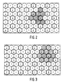
- a channel set (RF carrier and / or code word set) used in this cell can be repeated at sufficiently large spatial distances (determined by co-channel interference occurring) from one cell to another (cf. FIGS. 2 and 3).
- the possibility of using the same RF carrier frequency in the remote radio cell and / or using different code word sets leads to additional flexibility and freedom in reuse planning and facilitates the introduction of small cell structures.
- the method of dynamic, flexible channel allocation can be used, a smaller "effective" co-channel repetition distance and thus a larger network capacity being able to be achieved.
- 2 and 3 show the frequency allocation in homogeneous networks (or homogeneous subnetworks), the radio cells being combined into cell groups (clusters) consisting of a number of radio cells. Different channel sets are used in the different cells of a cell group. In this case, several channel sets can be assigned to the fixed radio station BS within a radio cell. The distribution of the channel sets in a cell group is repeated periodically in space.
- a certain co-channel repetition distance is associated with the size of the cell group, the co-channel repetition distance and thus also the size of the cell group to be selected in the network design such that certain requirements are met for freedom from interference in the network.
- a total bandwidth of 25 MHz available in the digital radio transmission system for example, 20 channel sets (each with 32 message channels) with a transmission bandwidth of approximately 1.25 MHz can be formed.
- adjacent radio cells are separated from one another by different carrier frequencies and co-channel cells by different code words, then in the broadband direction, ie in the direction from the fixed radio station BS to the mobile radio stations MS cell groups with, for example, three or four radio cells per cell group (see FIGS. 2 and 3).
- FIGS. 2 and 3 illustrates the broadband direction from the fixed radio station BS to the mobile radio stations MS cell groups with, for example, three or four radio cells per cell group.
- the numbers 1 to 3 denote different carrier frequencies and the letters A to D different code sets.
- the numbers 1 to 3 denote different carrier frequencies and the letters A to D different code sets.
- a narrowband transmission with frequency channels in a 25 KHz grid can be provided.
- the frequency division is not fixed in the radio cells themselves, rather the frequencies are freely assigned by the fixed radio station BS.
- Fig. 4 shows the block diagram of the transmitting part of the fixed radio station BS.
- the data / voice stream transmitted in the baseband is composed as follows.
- the digitized speech of each individual channel is first transcoded in a PCM transcoder 1 to the transmission method required for radio transmission with a correspondingly lower bit rate.
- a data source can be connected to the interface BB.
- a channel encoder 2 connected to the data source or transcoder 1
- a special channel coding is added to protect significant bits against transmission errors on the transmission channel. These Channel coding can vary depending on the service being transmitted.
- a multiplexer 3 connected to the channel encoder 2, the connection-accompanying signaling and the synchronization information originating from a synchronization circuit 4 are added to the data stream.
- the TDM signal (T Time Division ultiplex signal) at the output of TDM multiplexer 3 thus contains in the illustrated in Fig. 4 embodiment, four voice / data channels, one accompanying the connection signaling channel (for a TDM channel bundle) and for the synchronization in the mobile radio stations MS required synchronization bits.
- the synchronization bits are superimposed on the TDM signal, as suggested in P 35 11 430.4.
- the TDM signal at the output of the multiplexer 3 is multiplied by the respective code words generated by code generators 5, two bits being combined to form a symbol and spreading with the desired code.
- the code generator 5 is connected to a control device 15 and, at the command of the control device 15, inserts synchronization symbols instead of data symbols into the continuous data stream occurring at the output of the multiplexer 3.
- a modulation method adapted to the properties of the radio transmission channel is applied to the spread signal, for example the phase of a carrier signal originating from an oscillator 6 is then keyed with the spread signal, as a result of which a BPSK (binary.), which is linked to the information and the code word, is modulated at a low intermediate frequency Phase Shift Keying) signal is generated.
- the modulated CDM signal is fed to a summer 7, the output of which is connected to a bandpass filter 8. Eight of these modulated CDM signals, after addition and bandpass filtering, form a multi-level amplitude signal that is finally converted to the final frequency.
- a synthesizer 9 is provided as a mixed oscillator, which can be switched with corresponding stages within the frequency range of the digital radio transmission system.
- the synthesizer 9 is designed only for the few possible frequencies of the FDM stage (Frequency Division ultiplex M-stage).
- the CDM signal is mixed with the corresponding frequency supplied by the synthesizer 9 in a device 10 which is connected to a bandpass filter 11.
- the output of the bandpass filter 11 is connected to a power amplifier 12 and the filtered and amplified transmission signal reaches the antenna 14 via a transmitter coupler 13.
- the transmitter coupler 13 is completely eliminated.
- the channel and code generator setting, the correct selection of the channel coding and the insertion of messages into the organizational data stream are carried out by means of the control device 15 arranged in the fixed radio station BS.
- the selected radio transmission channel can be a TDM channel in a CDM level (cf. P 35 11 430.4).
- Fig. 5 shows the block diagram of the receiving part of the mobile radio station MS.
- the signal received by a common transmitting / receiving antenna 16 passes through a reception filter of a duplexer 17 to the input stage 18 of the receiver.
- the requirements for the reception filter of the duplexer 17 are relatively low, so that there is also an inexpensive solution for mobile radio stations MS with low service requirements, for example simple data radio.
- the signal is amplified in the input stage 18 and then mixed with an synthesizer frequency originating from a synthesizer 19 to an intermediate frequency.
- the intermediate frequency signal is fed to an IF section 20, in which the signal is further amplified and filtered.
- a simple synthesizer can also be used for the synthesizer 19, as for the synthesizer 9 of the fixed radio station BS, which can be implemented inexpensively.
- Filters are arranged in the ZF part 20, which serve the adjacent channel selection to differentiate from adjacent broadband channels or to suppress mixed products. The actual noise filtering takes place in correlators 23 to 25.
- An amplitude control circuit 21 is connected to the IF part 20, which raises the output signal of the IF part 20 to a sufficient level for driving the subsequent circuits and prevents possible overdriving of these circuits.
- the amplitude control circuit 21 compensates for different radio field attenuations and level fluctuations due to shadowing, so that linear processing can be carried out in the subsequent devices of the mobile radio station MS.
- the control time constant of the amplitude control circuit 21 is essentially determined by these shadows.
- the IF signal which is regulated in terms of power, at the output of the amplitude control circuit 21 is converted into the baseband in a demodulator 22 connected to the latter.
- This can be done, for example, when using a BPSK modulation on the principle of a Costass loop, so that frequency and phase are also taken into account.
- Ambiguities by integer multiples of 180 ° can be recognized and compensated accordingly based on the polarity of the received synchronous words (cf. P 35 11 430.4).
- the demodulator 22 With the demodulator 22 are three correlators 23, 24 and 25 connected, which are set by a control device 26 to the currently valid codes 1 and 2 and to a synchronous code valid for the entire channel bundle in the radio zone.
- the received organizational data stream is evaluated by means of the control device 26 by reading out the data of the services desired by the subscriber and the data for the radio transmission channels provided for the type of device, selecting a radio transmission channel identified as free in the organizational data stream and also selectable in the mobile radio station MS, and then an access signal is sent on this selected radio transmission channel to the fixed radio station BS.
- the output signal of the correlators 23 to 25 is used on the one hand to derive the symbol clock, frame clock and bit clock and on the other hand this is used to measure the currently valid multipath profile. Since a uniform synchronizing code with a correspondingly higher level is emitted in the entire channel bundle at the same time (cf. P35 11 430.4), this results in reliable synchronization detection and measurement of the multi-way profile.
- the outputs of the correlators 24 and 25 are connected to sampling circuits 27, 28 which sample the output signals of the correlators 24 and 25 and feed the respective result to a decision stage 29.
- the results of the scans running in synchronization with the echoes of the multipath propagation are weighted in decision stage 29 in proportion to the amplitude of the echoes (by means of a device 30).
- Decision stage 29 has the task of estimating the code sent and the polarity of the code. The estimated value thus allows the selection of the one sent with the greatest probability Symbol.
- the output signal is fed to a TDM demultiplexer 31 connected to decision stage 29.
- the demultiplexer 31 is connected to a channel decoder 32 at whose output the transmitted data stream is available again.
- the digital speech signal is decoded in a speech decoder 33, fed to a D / A converter and a loudspeaker connected to it.
- the data occurring at the output of the channel decoder 32 can be immediately e.g. displayed or printed out.
Abstract
Description
Die Erfindung betrifft ein digitales Funkübertragungssystem gemäß dem Oberbegriff des Patentanspruchs 1.The invention relates to a digital radio transmission system according to the preamble of
Zur Nachrichtenübertragung über ein von einer Vielzahl von Teilnehmern gemeinsam benutztes Übertragungsmedium (z.B. Leitung, Funkstrecke) sind drei Grundverfahren bekannt, nämlich das Codemultiplex-Verfahren, das Frequenz-multiplex-Verfahren und das Zeitmultiplex-Verfahren.Three basic methods are known for transmitting messages via a transmission medium (e.g. line, radio link) that is shared by a large number of subscribers, namely the code division multiplex method, the frequency multiplex method and the time division multiplex method.
Beim Codemultiplex-Verfahren werden beispielsweise die verschiedenen, über ein gemeinsames Übertragungsmedium geführten Nachrichten durch Basis-Modulation einem Träger aufmoduliert und das sich ergebende im Vergleich zur Kanalbandbreite schmalbandige Signal wird durch Multiplex-Modulation mit Hilfe eines den Empfänger kennzeichnenden Codeworts auf die Kanalbandbreite spektral gespreizt.In the case of code multiplexing, for example, the various messages carried over a common transmission medium are modulated onto a carrier by base modulation, and the resulting narrow-band signal compared to the channel bandwidth is spectrally spread to the channel bandwidth by means of a code word characterizing the receiver.
Die Erkennung des Signals erfolgt nicht durch zeitliche oder frequenzmäßige Selektion, sondern anhand der spektralen Codierung. Die im Codemultiplex-Kanal überlagerte Vielzahl von spektralcodierten Nachrichten werden im Empfänger anhand des diesem zugeordneten Codeworts selektiert.The signal is not recognized by temporal or frequency selection, but by means of the spectral coding. The multiplicity of spectrally coded messages superimposed in the code division multiplex channel are selected in the receiver on the basis of the code word assigned to them.
Beim Frequenzmultiplex-Verfahren wird die zur Nachrichtenübertragung zur Verfügung stehende Gesamtbandbreite in schmale Frequenzbänder unterteilt, welche jeweils einem Nachrichtenübertragungskanal entsprechen. Für die Dauer der Funkübertragung steht dem Teilnehmer ein solches schmales Frequenzband zur Verfügung.In the frequency division multiplex method, the total bandwidth available for message transmission is divided into narrow frequency bands, each of which corresponds to a message transmission channel. The subscriber has one for the duration of the radio transmission narrow frequency band available.
Beim Zeitmultiplex-Verfahren steht jedem Teilnehmer die gesamte Bandbreite eines einzigen Funkkanals zur Verfügung, welchen der Teilnehmer aber nur für kurze Zeitabschnitte benutzen darf. Die Zeichen oder Zeichenfolgen verschiedener Teilnehmer sind ineinander verschachtelt und werden mit entsprechend höherer Bitrate im einzigen Funkkanal übertragen, wobei der jeweils einem Teilnehmer zugeordnete Zeitkanal sich periodisch mit der Rahmenperiodendauer wiederholt.In the time-division multiplex method, the entire bandwidth of a single radio channel is available to each subscriber, which the subscriber may only use for short periods of time. The characters or character strings of different subscribers are interleaved and are transmitted at a correspondingly higher bit rate in the single radio channel, the time channel assigned to each subscriber being repeated periodically with the frame period.
Aus der DE-OS 25 37 683 ist ein Funkübertragungssystem mit ortsfesten Funkstationen und beweglichen Funkstationen bekannt, bei welchen verschiedene Kanalzugriffsverfahren mit asynchronem Zeitmultiplex, mit Codemultiplex und mit Frequenzmultiplex verwendet werden.From DE-OS 25 37 683 a radio transmission system with fixed radio stations and mobile radio stations is known, in which different channel access methods with asynchronous time division, with code division and with frequency division are used.
Für die Codewort-Synchronisation wird eine inkohärente Trägerdemodulation verwendet. Ein Codegenerator erzeugt nacheinander je einen der neun verschiedenen Codes, die die ortsfesten Landfunkstellen kennzeichnen. Nachdem dieser Code mit dem Empfangssignal synchronisiert ist, wird das ZF-Signal damit multipliziert, wodurch das breite Spektrum in die Nachrichtenbandbreite transformiert wird. Anschließend kann die empfangene Nachricht beispielsweise mit einem DPSK-Demodulator zurückgewonnen werden. Für die Synchronisation wird ein eigenes Codemuster mit einer Länge von beispielsweise 15 Bit verwendet, welches der Nachricht vorangestellt ist.An incoherent carrier demodulation is used for the code word synchronization. A code generator successively generates one of the nine different codes that identify the fixed land stations. After this code is synchronized with the received signal, the IF signal is multiplied by it, whereby the broad spectrum is transformed into the message bandwidth. The received message can then be recovered using a DPSK demodulator, for example. A separate code pattern with a length of 15 bits, for example, is used for the synchronization, which precedes the message.
Auch Kombinationen der vorgenannten Verfahren und deren Anwendung in einem digitalen Funkübertragungssystem sind bekannt. Beispielsweise ist in "Nachrichtentechnik, Elektronik + Telematic 38 (1984), Heft 7, Seiten 264 bis 268" ein digitales Funkübertragungssystem beschrieben, bei dem das Zeitmultiplex-Verfahren in Kombination mit Codespreizung verwendet wird, wobei jedoch keine Trennung verschiedener Teilnehmer unter Anwendung des Codemultiplexverfahrens erfolgt. In den Zeitkanälen zur Sprach-und/oder Datenübertragung (Kommunikationskanal TCH) werden nacheinander eine Bit-Folge zur Ermittlung des Bit-Takts (Synchron), ein Rahmen-Synchronisationswort (Vorspann) und die Bit-Folge der Nachricht selbst übertragen. Die Zeitkanäle zur Nachrichtenübertragung (3x20 TCH) sind mit Organisationskanälen (3 CCH) zu einem Zeitmultiplexrahmen mit der Zeitdauer 31,5 msec. angeordnet. Soll als Nachricht das Sprachsignal übertragen werden, so kann zur Analog-/Digitalwandlung die adaptive Deltamodulation verwendet werden. Die dabei entstehenden Nachrichtenzeichen (Bit) werden im Sender mit einem Code überlagert. Es hat sich als vorteilhaft erwiesen, die enzelnen Nachrichtenzeichen in Blöcke zu je vier Bit zusammen zu fassen und die so entstehenden Blöcke mit einem orthogonalen Alphabet zu spreizen. Der dabei verwendete Spreizfaktor ist ein Kompromiß, um die Vorteile der Bandspreizung mit der Forderung nach Frequenzökonomie miteinander zu vereinigen.Combinations of the aforementioned methods and their use in a digital radio transmission system are also known. For example, in "Telecommunications, Electronics + Telematic 38 (1984), No. 7, pages 264 to 268 "describes a digital radio transmission system in which the time-division multiplex method is used in combination with code spreading, but there is no separation of different subscribers using the code-division multiplex method. In the time channels for voice and / or data transmission (communication channel TCH), one bit is consecutively -Transmission to determine the bit clock (synchronous), a frame synchronization word (header) and the bit sequence of the message itself transmitted.The time channels for message transmission (3x20 TCH) are with organization channels (3 CCH) to a time-division multiplex frame with the duration 31.5 msec .. If the voice signal is to be transmitted as a message, adaptive delta modulation can be used for analog-to-digital conversion. The message characters (bits) that are created in this way are overlaid with a code in the transmitter. It has proven to be advantageous the individual message characters together in blocks of four bits each and grasp the resulting blocks with an orthogonal alphabet. The spreading factor used here is a compromise in order to combine the advantages of band spreading with the demand for frequency economy.
Weiterhin ist ein Nachrichtenübertragungsverfahren vorgeschlagen worden DE-A-3 447 107 entsprechend du europäischen Anmeldung EP-A-0 188 836, bei dem in Hin- und Rückrichtung des Nachrichtenübertragungskanals jeweils ein anderes Modulationsverfahren angewandt wird. Zur Nachrichtenübertragung greifen die beweglichen Funkstationen auf einen aus einer Vielzahl von Nachrichtenkanälen zu. In der Richtung von der ortsfesten Funkstation zu den dieser zugeordneten beweglichen Funkstationen ist jeder Nachrichtenkanal durch Spreizmodulation gespreizt.Furthermore, a message transmission method has been proposed DE-A-3 447 107 in accordance with European application EP-A-0 188 836, in which a different modulation method is used in the forward and backward direction of the message transmission channel. The mobile radio stations access one of a large number of message channels for message transmission. In the direction from the fixed radio station to the mobile radio stations assigned to it, each message channel is spread by spread modulation.
Die gespreizten Nachrichtenkanäle werden einander überlagert und das dadurch erhaltene breitbandige Summensignal wird in einem gemeinsamen Frequenzband übertragen. In der Richtung von den beweglichen Funkstationen zu der ortsfesten Funkstation erfolgt die Nachrichtenübertragung in voneinander getrennten, schmalbandigen Frequenzkanälen.The spread news channels are superimposed on one another and the broadband sum signal thus obtained is transmitted in a common frequency band. In the direction from the mobile radio stations to the fixed radio station, the messages are transmitted in separate, narrowband frequency channels.
Für die Sprachübertragung, in der Richtung von der ortsfesten Funkstation zu den beweglichen Funkstationen, wird die verwendete Spreizmodulation von der ortsfesten Funkstation ausgewählt und beim Verbindungsaufbau der beweglichen Funkstation mitgeteilt. Für die Übertragung von Signalisierungen an die der ortsfesten Funkstation zugeordneten beweglichen Funkstationen, wird in der Richtung von der ortsfesten Funkstation zu den beweglichen Funkstationen, eine für alle beweglichen Funkstationen gemeinsame Spreizmodulation verwendet.For the voice transmission, in the direction from the fixed radio station to the mobile radio stations, the spread modulation used is selected by the fixed radio station and communicated to the mobile radio station when the connection is established. For the transmission of signaling to the mobile radio stations assigned to the stationary radio station, spread modulation common to all mobile radio stations is used in the direction from the stationary radio station to the mobile radio stations.
Zur Unterscheidung von in benachbarten Funkzellen angeordneten ortsfesten Funkstationen senden diese, in Richtung von der ortsfesten Funkstation zu den beweglichen Funkstationen, in unterschiedlichen Frequenzbändern. In den ortsfesten Funkstationen sind Schmalband-Empfänger angeordnet, welche während des Betriebs auf mehrere Frequenzkanäle umschaltbar sind. Die Zahl der in der beweglichen Funkstation schaltbaren Sendefrequenzen ist geringer als die Zahl der in der ortsfesten Funkstation schaltbaren Empfangsfrequenzen. Beispielsweise kann in der ortsfesten Funkstation eine Umschaltung auf 1.000 Frequenzen und in der beweglichen Funkstation eine Umschaltung auf 40 Frequenzen vorgenommen werden.In order to distinguish between fixed radio stations arranged in adjacent radio cells, they transmit in different frequency bands in the direction from the fixed radio station to the movable radio stations. Narrow-band receivers are arranged in the fixed radio stations and can be switched over to several frequency channels during operation. The number of transmitting frequencies that can be switched in the mobile radio station is less than the number of receiving frequencies that can be switched in the fixed radio station. For example, a switchover to 1,000 frequencies can be carried out in the fixed radio station and a switchover to 40 frequencies in the mobile radio station.
Um die Interferenzsituation günstig zu beeinflussen, werden in jeder ortsfesten Funkstation die dort verwendeten Empfangsfrequenzen verwaltet. Bei Empfangsstörungen wird die betroffene Verbindung, in Richtung von der beweglichen Funkstation zu der ortsfesten Funkstation, auf einen anderen nicht gestörten Frequenzkanal, auf welchen sowohl die ortsfeste Funkstation als auch die bewegliche Funkstation umschalten kann, umgeschaltet. Die Empfangseinrichtung in der ortsfesten Funkstation zum Drahtnetz des öffentlichen Fernspechsystems hin bleibt weiterhin an der Verbindung beteiligt.In order to influence the interference situation favorably, the reception frequencies used there are managed in each fixed radio station. In the event of reception interference the connection concerned, in the direction from the mobile radio station to the fixed radio station, is switched to another undisturbed frequency channel on which both the fixed radio station and the mobile radio station can switch. The receiving device in the fixed radio station to the wire network of the public telephony system remains involved in the connection.
Der Erfindung liegt die Aufgabe zugrunde, in einem digitalen Funkübertragungssystem die Bildung von Nachrichtenkanälen derart vorzunehmen, daß eine Anpassung an inhomogene Verkehrsdichten und eine kostengünstige Realisierung für den Sender in der ortsfesten Funkstation und den Empfänger in der beweglichen Funkstation erreicht wird.The invention has for its object to make the formation of message channels in a digital radio transmission system such that an adaptation to inhomogeneous traffic densities and an inexpensive implementation for the transmitter in the fixed radio station and the receiver in the mobile radio station is achieved.
Diese Aufgabe wird erfindungsgemäß bei einem digitalen Funkübertragungssystem mit den Merkmalen des Patentanspruchs 1 gelöst.This object is achieved according to the invention in a digital radio transmission system with the features of
Durch die Anwendung der Spreizmodulation in der Übertragungsrichtung von der ortsfesten Funkstation zu den beweglichen Funkstationen lassen sich Mehrwege auflösen und auswerten und Interferenzen weitgehend vermeiden. Werden in den verschiedenen Funkzellen des digitalen Funkübertragungssystems verschiedene Codes und das gleiche Frequenzband verwendet (Trennung der Nachrichtenkanäle in den Funkzellen eines Clusters durch Codemultiplex) so kann die gleiche Frequenz in der Zellstruktur öfter wiederholt werden als bei einem reinen Frequenzmultiplexsystem. Dadurch wird das Übertragungsverfahren frequenzökonomischer.By using spread modulation in the transmission direction from the fixed radio station to the mobile radio stations, multipaths can be resolved and evaluated and interference largely avoided. If different codes and the same frequency band are used in the different radio cells of the digital radio transmission system (separation of the message channels in the radio cells of a cluster by code multiplex), the same frequency in the cell structure can be repeated more often than in a pure frequency multiplex system. This makes the transmission process more economical in terms of frequency.
Durch die Verwendung von verschiedenen Codes in den Funkzellen eines Clusters (Trennung der Nachrichtenkanäle von beweglichen Funkstationen innerhalb der gleichen Funkzelle durch Codemultiplex) werden innerhalb einer Funkzelle zusätzliche Nachrichtenkanäle zur Verfügung gestellt.By using different codes in the radio cells of a cluster (separation of the message channels from mobile radio stations within the same radio cell by code division) additional message channels are made available within a radio cell.
Durch die Verwendung von verschiedenen Frequenzbändern mit einer für die Funknetzplanung geeigneten Bandbreite (Flexiblität) sowohl in benachbarten Funkzellen als auch innerhalb einer Funkzelle kann beim erfindungsgemäßen digitalen Funkübertragungssystem eine gute Anpassung an inhomogene Verkehrsdichten vorgenommen werden. Dies erfolgt zum einen durch die Bildung von großen Funkzellen bei niedrigen Verkehrsdichten und kleinen Funkzellen bei hohen Verkehrsdichten und zum anderen durch die Belegung von mehreren Frequenzbändern innerhalb einer Funkzelle mit hoher Verkehrsdichte. Durch die Anwendung dieses Frequenzmultiplexverfahrens (Kanalsätze) wird ein einfacher Übergang von großen auf kleine Funkzellen ermöglicht. In Funkzellen mit sehr hoher Verkehrsdichte können unter Anwendung des Frequenzmultiplexverfahrens mehrere Kanalsätze (Nachrichtenkanäle mit gleichem Codesatz) betrieben werden, so daß sich die Bildung von Kleinstzellen vermeiden läßt.By using different frequency bands with a bandwidth suitable for radio network planning (flexibility) both in neighboring radio cells and within a radio cell, the digital radio transmission system according to the invention can be adapted well to inhomogeneous traffic densities. This takes place on the one hand through the formation of large radio cells at low traffic densities and small radio cells at high traffic densities and on the other hand through the occupancy of several frequency bands within a radio cell with high traffic density. The use of this frequency division multiplex method (channel sets) enables a simple transition from large to small radio cells. In radio cells with a very high traffic density, several channel sets (message channels with the same code set) can be operated using the frequency division multiplex method, so that the formation of very small cells can be avoided.
Unter Anwendung des Zeitmultiplexverfahrens können in jeder Codeebene zusätzliche Nachrichtenkanäle geschaffen werden, so daß die Übertragungskapazität im digitalen Funkübertragungssystem weiter erhöht werden kann. Dadurch können Sendeeinrichtungen in der ortsfesten Funkstation im Vergleich zu einem reinen Frequenzmultiplexsystem gespart werden.Using the time-division multiplex method, additional message channels can be created in each code level, so that the transmission capacity in the digital radio transmission system can be further increased. As a result, transmission devices in the fixed radio station can be saved in comparison to a pure frequency division multiplex system.
In den beiden Übertragungsrichtung des digitalen Funkübertragungssystems wird für die Bündelung von Nachrichtenkanälen unterschiedliche Kombinationen von Multiplexverfahren angewandt. Die Einfügung der zu sendenden Nachricht in die Nachrichtenkanäle unter Anwendung der Kombination von Codemultiplex-, Zeitmultiplex- und Frequenzmultiplexverfahren ist auch bei einem Übertragungssystem anwendbar, bei dem nur in eine Richtung gesendet wird. Durch die Anwendung des Codemultiplexverfahrens wird ein frequenzökonomisches Übertragungssystem dann erhalten, wenn die Signale alle synchron und mit gleicher Leistung beim Empfänger eintreffen, was beim Mobilfunk in der Richtung von ortsfester Funkstation zu jeder einzelnen beweglichen Funkstation gegeben ist.In the two transmission directions of the digital radio transmission system, different combinations of multiplexing methods are used for the bundling of message channels. The insertion of the ones to be sent Message in the message channels using the combination of code division multiplexing, time division multiplexing and frequency division multiplexing is also applicable to a transmission system in which transmission is only in one direction. By using the code multiplex method, a frequency-economical transmission system is obtained when the signals all arrive synchronously and with the same power at the receiver, which is the case with mobile radio in the direction from the fixed radio station to each individual mobile radio station.
Die Bildung der Nachrichtenkanäle in einem digitalen Funkübertragungssystem wird im folgenden anhand in der Zeichnung dargestellter Ausführungsformen näher beschrieben und erläutert. Es zeigt:
- Fig. 1
- die Multiplexbildung innerhalb einer Funkzelle
- Fig. 2
- die Frequenzwiederholung in der Zellstruktur bei drei verschiedenen Codesätzen,
- Fig. 3
- die Frequenzwiederholung in der Zellstruktur bei vier verschiedenen Codesätzen,
- Fig. 4
- das Blockschaltbild des Sendeteils der ortsfesten Funkstation und
- Fig. 5
- das Blockschaltbild des Empfangsteils in der beweglichen Funkstation.
- Fig. 1
- multiplexing within a radio cell
- Fig. 2
- frequency repetition in the cell structure with three different code sets,
- Fig. 3
- frequency repetition in the cell structure with four different code sets,
- Fig. 4
- the block diagram of the transmitting part of the fixed radio station and
- Fig. 5
- the block diagram of the receiving part in the mobile radio station.
Im digitalen Funkübertragungssystem sind ortsfeste Funkstationen BS räumlich nach einem Zellensystem angeordnet. Jeder ortsfesten Funkstation BS sind eine Anzahl von Funkübertragungskanälen zugeordnet, über welche Nachrichten zu beweglichen Funkstationen MS übertragen werden.In the digital radio transmission system, fixed radio stations BS are spatially arranged according to a cell system. A number of radio transmission channels are assigned to each fixed radio station BS, via which messages are transmitted to mobile radio stations MS.
In den beiden Übertragungsrichtungen werden für die Bündelung von Nachrichtenkanälen unterschiedliche Kombinationen von Multiplexverfahren angewandt. In der Übertragungsrichtung von der ortsfesten Funkstation BS zu den beweglichen Funkstationen MS wird die zu sendende Nachricht (Sprache oder Daten) in die Nachrichtenkanäle unter Anwendung von Codemultiplex-, Zeitmultiplex- und Frequenzmultiplexverfahren eingefügt. Hierzu sind in der ortsfesten Funkstation BS unter anderem ein TDM-Multiplexer 3, ein Codewortgenerator 5 und ein Synthesizer 9 angeordnet (vgl. Fig. 4). In der beweglichen Funkstation MS erfolgt die Trennung der Nachrichtenkanäle des empfangenen Digitalsignals unter Anwendung des Codemultiplex-, Zeitmultiplex- und Frequenzmultiplexverfahrens. Hierzu sind in der beweglichen Funkstation MS unter anderem ein Synthesizer 19, Korrelatoren 24 und 25 und ein TDM-Demultiplexer 31 (vgl. Fig. 5) vorgesehen. Für die Übertragungsrichtung von den beweglichen Funkstationen MS zur ortsfesten Funkstation BS erfolgt die Nachrichtenübertragung in voneinander getrennten, schmalbandigen Frequenzkanälen. Im folgenden wird die Multiplexbildung für die Übertragungsrichtung von der ortsfesten Funkstation BS zu den beweglichen Funkstationen MS näher beschrieben und erläutert.Different combinations of multiplexing methods are used in the two transmission directions for the bundling of message channels. In the direction of transmission from the fixed radio station BS to the mobile radio stations MS, the message to be sent (voice or data) is inserted into the message channels using code division multiplex, time division multiplex and frequency division multiplex methods. For this purpose, a
Eine ortsfeste Funkstation BS weist beispielsweise mindestens einen Kanalsatz, bestehend aus 32 Nachrichtenkanälen, auf. Die einzelnen Nachrichtenkanäle für die verschiedenen beweglichen Funkstationen MS in einem Kanalsatz sind durch verschiedene Spreizcodewörter (CDMA) und/oder verschiedene Zeitschlitze (TDMA) voneinander getrennt. In Fig. 1 sind drei solcher Kanalsätze dargestellt, wobei in dem gezeigten Beispiel Kanalsätze 1 und 2 zur gleichen Funkzelle und Kanalsatz 3 zu einer benachbarten Funkzelle gehören. Die Kennzeichnung der einzelnen Nachrichtenkanäle (Kanalkennung) ist in Fig. 1 durch die Zahlenfolge mit drei Ziffern verdeutlicht. Dabei bedeutet die erste Ziffer die Nummer des jeweiligen Zeitschlitzes, die zweite Ziffer das jeweils verwendete Codewort und die dritte Ziffer die jeweilige Nummer der verwendeten Trägerfrequenz. Die Bündelung der Nachrichtenkanäle in der Übertragungsrichtung von der ortsfesten Funkstation BS zu den beweglichen Funkstationen MS erfolgt durch die Aufeinanderfolge des Zeitmultiplex-, Codemultiplex- und schließlich Frequenzmultiplexverfahrens. Diese bevorzugte Aufeinanderfolge erleichtert die Realisierung der Sende-und Empfangseinrichtungen des digitalen Funkübertragungssystems.A fixed radio station BS has, for example, at least one channel set, consisting of 32 message channels. The individual message channels for the various mobile radio stations MS in a channel set are separated from one another by different spreading code words (CDMA) and / or different time slots (TDMA). 1 shows three such channel sets, with
Der Aufbau eines Kanalsatzes erfolgt z.B. dadurch, daß mehrere Zeitschlitze, von denen jeder die Information für jeweils einen Teilnehmer beinhaltet, zu einem Zeitmultiplexrahmen zusammengefaßt werden. In Fig. 1 umfaßt der Zeitmultiplexrahmen vier Zeitschlitze, z.B. Nachrichtenkanal 1.1.1 bis 4.1.1.A channel set is built up e.g. in that several time slots, each of which contains the information for one subscriber in each case, are combined to form a time-division multiplex frame. In Fig. 1 the time-division multiplex frame comprises four time slots, e.g. News channel 1.1.1 to 4.1.1.
Anschließend wird die Information solcher Zeitmultiplexrahmen mit geeignet gewählten Codewörtern gespreizt, welche es erlauben, mehrere Zeitmultiplexrahmen gleichzeitig und mit derselben Trägerfrequenz zu übertragen. Dabei erfolgt die Spreizung jedes dieser Zeitmultiplexrahmen mit einem Codewort, welches in diesem Kanalsatz nur diesem speziellen Zeitmultiplexrahmen zugeordnet ist.Das bedeutet zum einen, daß innerhalb eines Kanalsatzes jeder Zeitmultiplexrahmen für die Spreizung ein für ihn spezifisches und von den anderen Zeitmultiplexrahmen unterschiedliches Codewort enthält und zum anderen, daß die Information in den Zeitschlitzen eines Zeitmultiplexrahmens mit dem gleichen Codewort gespreizt wird.The information of such time-division multiplex frames is then spread with appropriately selected code words, which allow a plurality of time-division multiplex frames to be transmitted simultaneously and with the same carrier frequency. The spreading of each of these time-division multiplex frames takes place with a code word, which in this channel set is assigned only to this special time-division multiplex frame others that the information in the time slots of a time-division multiplex frame is spread with the same code word.
Bei der in Fig. 1 dargestellten Ausführungsform werden acht verschiedene Codewörter pro Kanalsatz verwendet, d.h. ein Kanalsatz enthält 8 verschieden Zeitmultiplexrahmen mit jeweils 4 Zeitkanälen, zusammen also 32 Nachrichtenkanäle pro Kanalsatz.In the embodiment shown in FIG. 1, eight different code words are used per channel set, ie a channel set contains 8 different time-division multiplex frames with 4 time channels each, so a total of 32 message channels per channel set.
Durch die Vergabe von ausgesuchten Codesymbolen für die Spreizung, wie z.B. pseudozufällige, orthogonale oder quasiorthogonale Codewörter, ist die gleichzeitige Übertragung von Nachrichten im Codemultiplex möglich. Die 8 individuellen Spreizcodes weisen eine Spreizung von 31, d.h. eine Länge von 31 Chips, auf. Dabei werden alle Codemultiplex-Kanäle von dem Sender der ortsfesten Funkstation BS mit gleicher Leistung und zeitsynchron gesendet. Durch die Verwendung von vier Symbolen in jedem Codemultiplex-Kanal (die vier Symbole lassen sich z.B. durch zwei antipodale Codewörter darstellen) lassen sich zwei Bit des Nutzsignals zu einem Symbol zusammenfassen. Dadurch verringert sich die Symbolrate gegenüber der Bitrate des Basisband um die Hälfte. Für die Codierung des Basisbandsignals und der Synchronisierung stehen sechs verschiedene Symbole zur Verfügung, von denen zwei ausschließlich für die Synchronisation verwendet werden. Werden acht indviduelle Spreizcodeebenen mit vier zeitlich gestaffelten Kanälen gebildet, so können 32 Nachrichtenkanäle von beispielsweise 16 kbit/s übertragen werden, welche nach Codespreizung einem gemeinsamen HF-Träger aufmoduliert werden. Bei Anwendung einer 4-Phasenmodulation ergibt sich für die Übertragung von 32 Nachrichtenkanälen z.B. eine Bandbreite von 1,25 MHz. Die Zeitstaffelung und damit die Zahl der Nachrichtenkanäle pro Spreizcodeebene hängt von der für jeden Nachrichtenübertragungskanal benötigten Bitrate ab.By assigning selected code symbols for the spread, e.g. pseudo-random, orthogonal or quasi-orthogonal code words, the simultaneous transmission of messages in code multiplex is possible. The 8 individual spread codes have a spread of 31, i.e. a length of 31 chips. All code multiplex channels are transmitted by the transmitter of the fixed radio station BS with the same power and synchronously. By using four symbols in each code division multiplex channel (the four symbols can be represented, for example, by two antipodal code words), two bits of the useful signal can be combined into one symbol. This reduces the symbol rate by half compared to the bit rate of the baseband. There are six different symbols available for coding the baseband signal and for synchronization, two of which are used exclusively for synchronization. If eight individual spread code levels are formed with four time-staggered channels, 32 message channels of, for example, 16 kbit / s can be transmitted, which are modulated onto a common RF carrier after code spreading. When using 4-phase modulation, the transmission of 32 message channels, e.g. a bandwidth of 1.25 MHz. The time grading and thus the number of message channels per spreading code level depends on the bit rate required for each message transmission channel.
Die beim erfindungsgemäßen digitalen Funkübertragungsverfahren stem vorgenommene Bündelung der Nachrichtenkanäle bringt eine Reihe von Vorteilen mit sich. Diese sind im einzelnen:
- Verringerung des Rayleigh-Fading-Einflußes
- Vermeidung von Symbolinterferenzen
- gute Frequenzökonomie
- flexible und leichte Anpassung an verschiedene Verkehrsdichten
- leichte Erweiterbarkeit des Systems
- Flexibilität in der reuse-Planung
- einfache Frequenzkoordination mit anderen Ländern oder Systemen.
- Reduction of the Rayleigh fading influence
- Avoiding symbol interference
- good frequency economy
- flexible and easy adaptation to different traffic densities
- easy expandability of the system
- Flexibility in reuse planning
- easy frequency coordination with other countries or systems.
Für die Spreizung können z.B. Gold-Codes verwendet werden. Eine Änderung des Spreizcodes hat nur geringen Einfluß auf die Empfangseinrichtung, da diese programmierbare Korrelatoren aufweist, welche von Verbindung zu Verbindung auf Anweisung des ortsfesten Funkstation BS neu eingestellt werden. Für die Übertragung solcher Einstellinformationen und zur Trennung der einzelnen Zeitkanäle (Nachrichtenkanäle) im Zeitmultiplexrahmen kann ein Organisationskanal vorgesehen sein.For the spreading e.g. Gold codes are used. A change in the spreading code has only little influence on the receiving device, since it has programmable correlators which are reset from connection to connection on the instruction of the fixed radio station BS. An organizational channel can be provided for the transmission of such setting information and for the separation of the individual time channels (message channels) in the time-division multiplex frame.
Wie bereits ausgeführt, werden die Zeitmultiplexrahmen eines Kanalsatzes im Sender der ortfesten Funkstation BS einander überlagert, gemeinsam verstärkt und auf einem HF-Träger über eine Antenne abgestrahlt. Im Empfänger der beweglichen Funkstation MS wird das empfangene Digitalsignal ins Basisband gemischt. Dann wird in dem dieser beweglichen Funkstation beim Verbindungsaufbau zugewiesenen Zeitschlitz, die Information durch Korrelation mit dem für diesen Nachrichtenkanal verwendeteten Codewort, das der beweglichen Funkstation ebenfalls beim Verbindungsaufbau mitgeteilt wird, zurückgewonnen. Im Empfänger der beweglichen Funkstation MS erfolgt also die Trennung der Nachrichtenkanäle des empfangenen Digitalsignals in umgekehrter Abfolge, d.h. Demultiplexen bezüglich Frequenz, Code und Zeit, wie bei der Bündelung der Nachrichtenkanäle in der ortsfesten Funkstation BS. Bei einer Rahmenlänge von z.B. 20ms für den Zeitmultiplexrahmen, einer Symboldauer des Spreizcodeworts von 25 µs und einer Spreizung von 31 liegt die Chipdauer bei 0,806 ns und die Chiprate bei 1,24 Mcps. Damit ist auch die Chipdauer klein genug um eine hinreichende Auflösung und Ausnutzung der Mehrwege zu erlauben und Fading-Einflüsse weigehend zu vermeiden.As already stated, the time-division multiplex frames of a channel set in the transmitter of the fixed radio station BS superimposed on one another, amplified together and radiated on an HF carrier via an antenna. The received digital signal is mixed into the baseband in the receiver of the mobile radio station MS. Then in the time slot assigned to this mobile radio station when the connection is established, the information is recovered by correlation with the code word used for this message channel, which is also communicated to the mobile radio station when the connection is established. In the receiver of the mobile radio station MS, the separation of the message channels of the received digital signal takes place in the reverse order, ie demultiplexing with regard to frequency, code and time, as in the bundling of the message channels in the fixed radio station BS. With a frame length of, for example, 20 ms for the time-division multiplex frame, a symbol duration of the spreading code word of 25 μs and a spread of 31, the chip duration is 0.806 ns and the chip rate is 1.24 Mcps. This also means that the chip duration is short enough to allow sufficient resolution and utilization of the multi-paths and to avoid fading influences as far as possible.
Wie bereits ausgeführt, is pro Kanalsatz mindestens ein Organisationskanal vorgesehen, auf dem die beweglichen Funkstationen MS zum Verbindungsaufbau zugreifen und über den der Verbindungsaufbau und einige Sonderdienste abgewickelt werden. Die beweglichen Funkstationen MS kennen die Frequenzlage der möglichen Kanalsätze, den entsprechenden Zeitkanal und die Codewörter für die innerhalb des digitalen Funkübertragungssystem vergebenen Organisationskanäle. Mit dieser Kenntnis kann die bewegliche Funkstation MS den für diese geeigneten Organisationskanal suchen und dort alle für den Zugriff (z.B. Frequenz der Schmalband-(Rück-)Richtung von beweglicher Funkstations MS zur ortsfesten Funkstation BS des jeweiligen Organisationskanals) und für den Verbindungsaufbau (z.B. Zeitkanal und Codewort für die Richtung von der ortsfesten Funkstation BS zur beweglichen Funkstation MS, sowie die Frequenz für die Schmalbandrichtung von der beweglichen Funkstation MS zu der ortsfesten Funkstation BS) benötigten Informationen empfangen.As already stated, at least one organizational channel is provided for each channel set, on which the mobile radio stations MS access the connection and via which the connection and some special services are handled. The mobile radio stations MS know the frequency position of the possible channel sets, the corresponding time channel and the code words for the organizational channels assigned within the digital radio transmission system. With this knowledge, the mobile radio station MS can search for the suitable organizational channel and there all for the access (eg frequency of the narrowband (reverse) direction from mobile radio stations MS to the fixed radio station BS of the respective organizational channel) and for the establishment of the connection (eg time channel and code word for the direction from the fixed radio station BS to the mobile radio station MS, and the frequency for the narrowband direction from the mobile radio station MS to the fixed radio station BS).
Werden in einer ortsfesten Funkstation BS mehr als 32 Nachrichtenkanäle benötigt, so können mehrere Kanalsätze unter Anwendung des Frequenzmultiplexverfahrens einander überlagert werden. Die verschiedenen Kanalsätze werden mit unterschiedlichen HF-Trägerfrequenzen abgestrahlt. In Fig. 1 sind der ortsfesten Funkstation BS1 die Kanalsätze 1 und 2 zugeordnet. Für die beiden der ortsfesten Funkstation BS1 zugeordneten Kanalsätze können, weil sie auf verschiedenen Trägerfrequenzen gesendet werden, die gleichen Codewörter verwendet werden.If more than 32 message channels are required in a fixed radio station BS, several channel sets can be superimposed on one another using the frequency division multiplex method. The different channel sets are emitted with different RF carrier frequencies. 1 the channel sets 1 and 2 are assigned to the fixed radio station BS1. The same code words can be used for the two channel sets assigned to the fixed radio station BS1 because they are transmitted on different carrier frequencies.
Die Trennung der Nachrichtenkanäle von benachbarten ortsfesten Funkstationen BS erfolgt entweder unter Anwendung des Frequenzmultiplexverfahrens (verschiedene HF-Träger für die in diesen ortsfesten Funkstationen BS verwendeten Kanalsätze), unter Anwendung des Codemultiplexverfahrens (verschiedene Codewortsätze bei den verwendeten Kanalsätzen) oder durch Kombinationen dieser beiden Multiplexverfahren. Bei der in Fig. 1 dargestellten Ausführungsform unterscheidet sich der Kanalsatz 3 der ortsfesten Funkstation BS2 von den beiden Kanalsätzen 1 und 2 der ortsfesten Funkstation BS1 sowohl im Codewortsatz (2. Ziffer der Kanalkennung) wie auch durch die verwendete HF-Trägerfrequenz (3. Ziffer der Kanalkennung). In genügend großen räumlichen Abständen (festgelegt durch auftretende Gleichkanalstörungen) von einer Zelle zur anderen kann ein in dieser Zelle eingesetzter Kanalsatz (HF-Träger und/oder Codewortsatz) wiederholt werden (vgl. Fig. 2 und 3). Dabei führt die Möglichkeit der Verwendung der gleichen HF-Trägerfrequenz in der entfernten Funkzelle und/oder unterschiedliche Codewortsätze zu benutzen, zu einer zusätzlichen Flexibilität und Freiheit in der reuse-Planung und erleichtert die Einführung von Kleinzellenstrukturen.The message channels are separated from adjacent fixed radio stations BS either using the frequency division multiplex method (different RF carriers for the channel sets used in these fixed radio stations BS), using the code multiplex method (different code word sets for the channel sets used) or by combinations of these two multiplex methods. In the embodiment shown in Fig. 1, the channel set 3 of the fixed radio station BS2 differs from the two
Beim erfindungsgemäßen digitalen Funkübertragungverfahren ist kein fester Duplexabstand zwischen Hin- und Rückkanal erforderlich, so daß das Verfahren der dynamischen, flexiblen Kanalzuweisung angewandt werden kann, wobei sich ein kleinerer "effektiver" Gleichkanalwiederholabstand und damit eine größere Netzkapazität erzielen läßt. In Fig. 2 und 3 ist die Frequenzzuweisung in homogenen Netzen (oder homogenen Teilnetzen) dargestellt, wobei die Funkzellen zu Zellgruppen (Cluster), bestehend aus einer Anzahl von Funkzellen, zusammengefaßt werden. In den verschiedenen Zellen einer Zellgruppe werden unterschiedliche Kanalsätze verwendet. Dabei können innerhalb einer Funkzelle auch mehrere Kanalsätze der ortsfesten Funkstation BS zugewiesen sein. Die Verteilung der Kanalsätze in einer Zellgruppe wird räumlich periodisch wiederholt. Mit der Größe der Zellgruppe ist ein bestimmter Gleichkanalwiederholabstand verbunden, wobei beim Netzentwurf der Gleichkanalwiederholabstand und damit auch die Größe der Zellgruppe so zu wählen ist, daß für die Interferenzfreiheit im Netz bestimmte Anforderungen erfüllt werden. Bei einer beispielsweise im digitalen Funkübertragungssystem zur Verfügung stehenden Gesamtbandbreite von 25 MHz können 20 Kanalsätze (mit je 32 Nachrichtenkanälen) mit einer Übertragungsbandbreite von ca. 1,25 MHz gebildet werden. Werden benachbarte Funkzellen durch unterschiedliche Trägerfrequenzen und Gleichkanalzellen durch unterschiedliche Codewörter von einander getrennt, so können in der Breitbandrichtung, d.h. in der Richtung von der ortsfesten Funkstation BS zu den beweglichen Funkstationen MS Zellgruppen mit beispielsweise drei oder vier Funkzellen pro Zellgruppe (vgl. Fig. 2 und Fig. 3) gebildet werden. In den Figuren 2 und 3 sind mit den Ziffern 1 bis 3 unterschiedliche Trägerfrequenzen und mit den Buchstaben A bis D unterschiedliche Codesätze bezeichnet. Bei einer Zellgruppe mit drei Funkzellen der gleichen Trägerfrequenz ergibt sich, bei der Verwendung von drei verschiedenen Codesätzen, in der Zellstruktur eine Frequenz- und Codesatzwiederholung in jeder neunten Funkzelle. Werden, wie in Fig. 3 dargestellt, vier verschiedene Codesätze verwendet, so tritt erst nach jeder zwölften Funkzelle eine Wiederholung der gleichen Frequenz-Code-Kombination auf.In the digital radio transmission method according to the invention, no fixed duplex distance between the forward and return channels is required, so that the method of dynamic, flexible channel allocation can be used, a smaller "effective" co-channel repetition distance and thus a larger network capacity being able to be achieved. 2 and 3 show the frequency allocation in homogeneous networks (or homogeneous subnetworks), the radio cells being combined into cell groups (clusters) consisting of a number of radio cells. Different channel sets are used in the different cells of a cell group. In this case, several channel sets can be assigned to the fixed radio station BS within a radio cell. The distribution of the channel sets in a cell group is repeated periodically in space. A certain co-channel repetition distance is associated with the size of the cell group, the co-channel repetition distance and thus also the size of the cell group to be selected in the network design such that certain requirements are met for freedom from interference in the network. With a total bandwidth of 25 MHz available in the digital radio transmission system, for example, 20 channel sets (each with 32 message channels) with a transmission bandwidth of approximately 1.25 MHz can be formed. If adjacent radio cells are separated from one another by different carrier frequencies and co-channel cells by different code words, then in the broadband direction, ie in the direction from the fixed radio station BS to the mobile radio stations MS cell groups with, for example, three or four radio cells per cell group (see FIGS. 2 and 3). In FIGS. 2 and 3, the
Für die Übertragungsrichtung von den beweglichen Funkstationen MS zu der ortsfesten Funkstation BS kann beispielsweise eine Schmalbandübertragung mit Frequenzkanälen im 25 KHz-Raster vorgesehen sein. In den Funkzellen selbst ist die Frequenzeinteilung nicht fest, vielmehr werden die Frequenzen von der ortsfesten Funkstelle BS frei vergeben.For the transmission direction from the mobile radio stations MS to the fixed radio station BS, for example, a narrowband transmission with frequency channels in a 25 KHz grid can be provided. The frequency division is not fixed in the radio cells themselves, rather the frequencies are freely assigned by the fixed radio station BS.
Fig. 4 zeigt das Blockschaltbild des Sendeteils der ortsfesten Funkstation BS. Der im Basisband übertragene Daten-/Sprachstrom setzt sich folgendermaßen zusammen. Die digitalisierte Sprache jedes einzelnen Kanals wird zunächst in einem Transcoder 1 von PCM auf das für die Funkübertragung erforderliche Übertragungsverfahren mit entsprechend geringerer Bitrate umcodiert. An der Schnittstelle B-B kann eine Datenquelle angeschlossen werden. In einem mit der Datenquelle bzw. den Transcoder 1 verbundenen Kanalcodierer 2 wird eine spezielle Kanalcodierung zum Schutz signifikanter Bits gegen Übertragungsfehler auf dem Übertragungskanal hinzugefügt. Diese Kanalcodierung kann je nach zu übertragendem Dienst unterschiedlich sein. In einem mit dem Kanalcodierer 2 verbundenen Multiplexer 3 wird in den Datenstrom die verbindungsbegleitende Signalisierung und die von einer Synchronisierschaltung 4 herrührende Synchronisationsinformation hinzugefügt. Das TDM-Signal (Time Division Multiplex-Signal) am Ausgang des TDM-Multiplexers 3 enthält also bei der in Fig. 4 dargestellten Ausführungsform vier Sprach-/Datenkanäle, einen verbindungsbegleitenden Signalisierungskanal (für ein TDM-Kanalbündel) sowie die für die Synchronisation in den beweglichen Funkstationen MS erforderlichen Synchronisationsbits. Die Synchronisationsbits werden in das TDM-Signal eingeblendet, wie dies in der P 35 11 430.4 vorgeschlagen ist.Fig. 4 shows the block diagram of the transmitting part of the fixed radio station BS. The data / voice stream transmitted in the baseband is composed as follows. The digitized speech of each individual channel is first transcoded in a
Das TDM-Signal am Ausgang des Multiplexers 3 wird mit den jeweiligen von Codegeneratoren 5 erzeugten Codeworten multipliziert, wobei jeweils zwei Bit zu einem Symbol zusammengefaßt und mit dem gewünschten Code gespreizt werden. Der Codegenerator 5 ist mit einer Steuereinrichtung 15 verbunden und fügt auf Befehl der Steuereinrichtung 15 Synchronisiersymbole anstelle von Datensymbolen in den am Ausgang des Multiplexers 3 auftretenden kontinuierlichen Datenstrom ein. Auf das gespreizte Signal wird ein den Eigenschaften des Funkübertragungskanals angepaßtes Modulationsverfahren angewandt, beispielsweise wird mit dem gespreizten Signal dann die Phase eines aus einem Oszillator 6 stammenden Trägersignals umgetastet, wodurch ein mit der Information und dem Codewort verknüpftes, bei einer niedrigen Zwischenfrequenz moduliertes BPSK (Binary Phase Shift Keying) Signal entsteht. Das modulierte CDM-Signal wird einem Summierer 7 zugeführt, dessen Ausgang mit einem Bandpaßfilter 8 verbunden ist. Acht dieser modulierten CDM-Signale bilden nach Addition und Bandpaßfilterung ein in der Amplitude mehrstufiges Gesamtsignal, das schließlich auf die Endfrequenz umgesetzt wird.The TDM signal at the output of the
Hierzu ist als Mischoszillator ein Synthesizer 9 vorgesehen, welcher innerhalb des Frequenzbereiches des digitalen Funkübertragungssystems mit entsprechenden Stufen geschaltet werden kann. Der Synthesizer 9 ist nur für die wenigen möglichen Frequenzen der FDM-Stufe (Frequency Division Multiplex-Stufe) ausgelegt. Die Mischung des CDM-Signals mit der entsprechenden vom Synthesizer 9 gelieferten Frequenz erfolgt in einer Einrichtung 10, welche mit einem Bandpaßfilter 11 verbunden ist. Der Ausgang des Bandpaßfilters 11 ist mit einem Leistungsverstärker 12 verbunden und das herausgefilterte und verstärkte Sendesignal gelangt über einen Senderkoppler 13 zur Antenne 14. Bei kleineren ortsfesten Funkstationen BS mit bis zu 32 Nachrichtenübertragungskanälen entfällt der Senderkoppler 13 völlig.For this purpose, a
Die Kanal- und Codegeneratoreinstellung, die richtige Auswahl der Kanalcodierung und die Einfügungen von Meldungen in den Organisationsdatenstrom erfolgt mittels der in der ortsfesten Funkstation BS angeordneten Steuereinrichtung 15. Der ausgewählte Funkübertragungskanal kann dabei ein TDM-Kanal in einer CDM-Ebene sein (vgl. P 35 11 430.4).The channel and code generator setting, the correct selection of the channel coding and the insertion of messages into the organizational data stream are carried out by means of the
Fig. 5 zeigt das Blockschaltbild des Empfangsteils der beweglichen Funkstation MS. Das von einer gemeinsamen Sende-/Empfangstenne 16 empfangene Signal gelangt über ein Empfangsfilter eines Duplexers 17 zur Eingangsstufe 18 des Empfängers. Die Anforderungen an das Empfangsfilter des Duplexers 17 sind relativ gering, so daß sich auch für bewegliche Funkstationen MS mit geringer Diensteanforderung, z.B. einfaches Datenfunkgerät, eine kostengünstige Lösung ergibt. In der Eingangsstufe 18 wird das Signal verstärkt und dann mit einer aus einem Synthesizer 19 stammenden Synthesizerfrequenz auf eine Zwischenfrequenz gemischt.Fig. 5 shows the block diagram of the receiving part of the mobile radio station MS. The signal received by a common transmitting / receiving
Das Zwischenfrequenzsignal wird einem ZF-Teil 20 zugeführt, in dem eine weitere Verstärkung und Filterung des Signals vorgenommen wird. Auch für den Synthesizer 19 kann wie für den Synthesizer 9 der ortsfesten Funkstation BS ein einfacher Synthesizer verwendet werden, welcher sich kostengünstig realisieren läßt. Im ZF-Teil 20 sind Filter angeordnet, welche die Nachbarkanalselektion zur Abgrenzung gegen benachbarte Breitbandkanäle bzw. zur Unterdrückung von Mischprodukten dienen. Die eigentliche Rauschfilterung erfolgt in Korrelatoren 23 bis 25. Mit dem ZF-Teil 20 ist eine Amplituden-Regelschaltung 21 verbunden, welche das Ausgangssignal des ZF-Teils 20 auf einen ausreichenden Pegel zur Ansteuerung der nachfolgenden Schaltungen anhebt und eine mögliche Übersteuerung dieser Schaltungen verhindert. Die Amplituden-Regelschaltung 21 gleicht unterschiedliche Funkfelddämpfungen und Pegelschwankungen aufgrund von Abschattungen aus, so daß in den nachfolgenden Einrichtungen der beweglichen Funkstation MS eine lineare Verarbeitung durchgeführt werden kann. Die Regelzeitkonstante der Amplituden-Regelschaltung 21 wird im wesentlichen von diesen Abschattungen bestimmt.The intermediate frequency signal is fed to an
Das in der Leistung geregelte ZF-Signal am Ausgang der Amplituden-Regelschaltung 21 wird in einem mit dieser verbundenen Demodulator 22 ins Basisband umgesetzt. Dies kann beispielsweise bei Anwendung einer BPSK-Modulation nach dem Prinzip einer Costasschleife durchgeführt, so daß Frequenz und Phase mit berücksichtigt werden. Mehrdeutigkeiten um ganzzahlige Vielfache von 180° können anhand der Polarität der empfangenen Synchronworte (vgl. P 35 11 430.4) erkannt und entsprechend ausgeglichen werden.The IF signal, which is regulated in terms of power, at the output of the
Mit dem Demodulator 22 sind drei Korrelatoren 23, 24 und 25 verbunden, welche von einer Steuereinrichtung 26 auf die gerade gültigen Codes 1 und 2 und auf einen in der Funkzone für das gesamte Kanalbündel gültigen Synchroncode eingestellt werden. Mittels der Steuereinrichtung 26 wird der empfangene Organisationsdatenstrom ausgewertet, indem die Daten der von dem Teilnehmer gewünschten Dienste und die Daten für die Geräteart vorgesehenen Funkübertragungskanäle ausgelesen werden, ein im Organisationsdatenstrom als frei ausgewiesener und auch im in der beweglichen Funkstation MS schaltbarer Funkübertragungskanal auswählt wird und anschließend ein Zugriffssignal auf diesem ausgewählten Funkübertragungskanal zur ortsfesten Funkstation BS gesendet wird.With the
Das Ausgangssignal der Korrelatoren 23 bis 25 wird einerseits zur Ableitung von Symboltakt, Rahmentakt sowie Bittakt verwendet anderseits wird dieses zur Vermessung des augenblicklich gültigen Mehrwegeprofils herangezogen. Da ein einheitlicher Synchroncode mit entsprechend größerem Pegel in dem gesamten Kanalbündel zum gleichen Zeitpunkt abgestrahlt wird (vgl. P35 11 430.4) ergibt sich eine sichere Synchronisationserkennung und Vermessung des Mehrwegeprofils.The output signal of the
Die Ausgänge der Korrelatoren 24 und 25 sind mit Abtastschaltungen 27, 28 verbunden, welche die Ausgangssignale der Korrelatoren 24 und 25 abtasten und das jeweilig Ergebnis einer Entscheidungsstufe 29 zuführen. Dabei werden die Ergebnisse der synchron zu den Echos der Mehrwegeausbreitung ablaufenden Abtastungen in der Entscheidungsstufe 29 proportional zur Amplitude der Echos (mittels einer Einrichtung 30) gewichtet. Die Entscheidungsstufe 29 hat die Aufgabe, den gesendeten Code und die Polarität des Codes zu schätzen. Der Schätzwert gestattet somit die Auswahl des mit der größten Wahrscheinlichkeit gesendeten Symbols. Nach der Symbol-Bit-Umwandlung in der Entscheidungsstufe 29 wird das Ausgangssignal einem mit der Entscheidungsstufe 29 verbundenen TDM-Demultiplexer 31 zugeführt. Der Demultiplexer 31 ist mit einem Kanal-Decodierer 32 verbunden an dessen Ausgang der gesendete Datenstrom wieder zur Verfügung steht. Bei digitaler Sprachübertragung wird in einem Sprachdecoder 33 das digitale Sprachsignal decodiert, einem D/A-Wandler und einem mit diesem verbundenen Lautsprecher zugeführt.The outputs of the
Ist in der beweglichen Funkstation MS beispielsweise die Dienstart Datendienst realisiert, so können die am Ausgang des Kanaldecodieres 32 auftretenden Daten sofort z.B. angezeigt oder ausgedruckt werden.If, for example, the data service service type is implemented in the mobile radio station MS, the data occurring at the output of the
Claims (6)
- Transmission method for a digital radio transmission system comprising in a cellular network base stations (BS) and a multiplicity of mutually independent mobile stations (MS), which have access to a multiplicity of communication channels for the transmission of messages, characterized in that different combinations of multiplex methods are used in both directions of transmission for combining communication channels, whereby for the direction of transmission from the base station (BS) to the mobile station (MS) the message to be transmitted is inserted by the base station (BS) into the communication channels (channel code X.Y.Z) by using a combination of the code-division multiplex, time-division multiplex and frequency-division multiplex methods (TDM multiplexer 3, codeword generator 5, synthesizer 9), and in the mobile station (MS) the communication channels of the received digital signal are separated with the aid of the code-division multiplex, time-division multiplex and frequency-division multiplex methods (synthesizer 19, correlators 24 and 25, TDM demultiplexer 31).
- Transmission method as claimed in Claim 1, characterized in that for the direction of transmission from the mobile stations (MS) to the base station (BS) the messages are transmitted over separated narrow-band frequency channels or over time-division channels or over separated code-division channels or a combination thereof.
- Transmission method as claimed in Claim 1, characterized in that the communication channels are combined in the base station (5) in the order of the time-division multiplex, code-division multiplex and frequency-division multiplex methods, and are separated in reverse order in the mobile station (MS).
- Transmission method as claimed in Claim 1, characterized in that in base stations (BS) with comparatively low capacity requirements the communication channels are combined within a radio cell while the code-division multiplex and time-division multiplex methods are used.
- Transmission method as claimed in Claim 1, characterized in that in base stations (BS) with comparatively very low capacity requirements the communication channels are combined within a radio cell while only the time-division multiplex method is used.
- Transmission method as claimed in Claim 1, characterized in that in the base station (BS) arbitrary combinations of code-division multiplex and time-division multiplex channels are converted to one carrier frequency.
Priority Applications (1)
| Application Number | Priority Date | Filing Date | Title |
|---|---|---|---|
| AT86201270T ATE77191T1 (en) | 1985-07-31 | 1986-07-21 | DIGITAL RADIO TRANSMISSION PROCESS. |
Applications Claiming Priority (2)
| Application Number | Priority Date | Filing Date | Title |
|---|---|---|---|
| DE19853527331 DE3527331A1 (en) | 1985-07-31 | 1985-07-31 | DIGITAL RADIO TRANSMISSION SYSTEM |
| DE3527331 | 1985-07-31 |
Publications (3)
| Publication Number | Publication Date |
|---|---|
| EP0211460A2 EP0211460A2 (en) | 1987-02-25 |
| EP0211460A3 EP0211460A3 (en) | 1989-03-15 |
| EP0211460B1 true EP0211460B1 (en) | 1992-06-10 |
Family
ID=6277205
Family Applications (1)
| Application Number | Title | Priority Date | Filing Date |
|---|---|---|---|
| EP86201270A Expired - Lifetime EP0211460B1 (en) | 1985-07-31 | 1986-07-21 | Digital radio transmission method |
Country Status (10)
| Country | Link |
|---|---|
| US (1) | US4799252A (en) |
| EP (1) | EP0211460B1 (en) |
| JP (1) | JPS6335025A (en) |
| AT (1) | ATE77191T1 (en) |
| AU (1) | AU591691B2 (en) |
| CA (1) | CA1280228C (en) |
| DE (2) | DE3527331A1 (en) |
| DK (1) | DK358086A (en) |
| FI (1) | FI82339C (en) |
| NO (1) | NO863040L (en) |
Cited By (1)
| Publication number | Priority date | Publication date | Assignee | Title |
|---|---|---|---|---|
| US6421368B1 (en) | 1991-06-03 | 2002-07-16 | Xircom Wireless, Inc. | Spread spectrum wireless communication system |
Families Citing this family (66)
| Publication number | Priority date | Publication date | Assignee | Title |
|---|---|---|---|---|
| FR2625389B1 (en) * | 1987-12-23 | 1990-05-04 | Trt Telecom Radio Electr | RADIO SYSTEM FOR ALLOWING THE EXCHANGE OF INFORMATION BETWEEN A SET OF STATIONS |
| JPH0622345B2 (en) * | 1988-01-14 | 1994-03-23 | 東京電力株式会社 | Mobile communication system |
| US4866710A (en) * | 1988-02-22 | 1989-09-12 | Motorola, Inc. | Reuse groups for scan monitoring in digital cellular systems |
| US5185739A (en) * | 1990-02-27 | 1993-02-09 | Motorola, Inc. | Time-allocation of radio carriers |
| US5199031A (en) * | 1990-08-31 | 1993-03-30 | Telefonaktiebolaget L M Ericsson | Method and system for uniquely identifying control channel time slots |
| US5134615A (en) * | 1990-10-05 | 1992-07-28 | Motorola, Inc. | Frequency agile tdma communications system |
| US5506864A (en) * | 1990-12-05 | 1996-04-09 | Interdigital Technology Corporation | CDMA communications and geolocation system and method |
| US5263045A (en) * | 1990-12-05 | 1993-11-16 | Interdigital Technology Corporation | Spread spectrum conference call system and method |
| US7020125B2 (en) * | 1990-12-05 | 2006-03-28 | Interdigital Technology Corporation | Broadband CDMA overlay system and method |
| US5193101A (en) * | 1991-02-04 | 1993-03-09 | Motorola, Inc. | On-site system frequency sharing with trunking systems using spread spectrum |
| CA2043127C (en) * | 1991-05-23 | 1996-05-07 | Martin Handforth | Wireless communication zone management system |
| US5195090A (en) * | 1991-07-09 | 1993-03-16 | At&T Bell Laboratories | Wireless access telephone-to-telephone network interface architecture |
| US5247702A (en) * | 1991-11-08 | 1993-09-21 | Teknekron Communications Systems, Inc. | Method and an apparatus for establishing a wireless communication link between a base unit and a remote unit |
| GB9201879D0 (en) * | 1992-01-29 | 1992-03-18 | Millicom Holdings Uk Ltd | Communication system |
| SE9200607D0 (en) * | 1992-02-28 | 1992-02-28 | Ericsson Telefon Ab L M | COMMUNICATION METHODS AND MEAN IN A TDMA CELLULAR MOBILE RADIO SYSTEM |
| DE4210305A1 (en) * | 1992-03-30 | 1993-10-07 | Sel Alcatel Ag | Method, transmitter and receiver for information data transmission with variable traffic volume and control station for coordinating several such transmitters and receivers |
| GB9209027D0 (en) * | 1992-04-25 | 1992-06-17 | British Aerospace | Multi purpose digital signal regenerative processing apparatus |
| FI97838C (en) * | 1992-05-06 | 1997-02-25 | Nokia Telecommunications Oy | the cellular network system |
| DE4227990C2 (en) * | 1992-08-21 | 2001-10-18 | Cell Gmbh Q | Radio transmission method using a fixed base station and a large number of independent fixed base stations |
| US5568472A (en) * | 1992-11-04 | 1996-10-22 | Ntt Mobile Communications Network Inc. | Code division multiple access mobile communication system |
| CA2105710A1 (en) * | 1992-11-12 | 1994-05-13 | Raymond Joseph Leopold | Network of hierarchical communication systems and method therefor |
| MX9307243A (en) * | 1992-11-24 | 1994-05-31 | Ericsson Telefon Ab L M | ANALOGUE RETRY. |
| FI925472A (en) * | 1992-12-01 | 1994-06-02 | Nokia Mobile Phones Ltd | Data transfer procedure and system |
| DE4242973C2 (en) * | 1992-12-18 | 1995-01-05 | Grundig Emv | Radio alarm system with a large number of message channels formed by the code multiplex method |
| DE4243026C2 (en) * | 1992-12-18 | 1994-10-13 | Grundig Emv | Radio alarm system with asynchronous transmission of messages via time channels of different periods |
| JPH0754991B2 (en) * | 1993-01-21 | 1995-06-07 | 日本電気株式会社 | Digital mobile radio communication system |
| DE69428492T2 (en) * | 1993-06-04 | 2002-05-23 | Motorola Inc | METHOD AND DEVICE FOR DYNAMICALLY SETTING A MAXIMUM NUMBER OF PARTICIPANTS ON A PHYSICAL CHANNEL |
| FI933129A0 (en) * | 1993-07-08 | 1993-07-08 | Nokia Mobile Phones Ltd | DATAOEVERFOERINGSFOERFARANDE FOER ETT DIGITALT CELLULAERT MOBILTELEFONSYSTEM OCH ETT DIGITALT CELLULAERT MOBILTELEFONSYSTEM |
| US5493563A (en) * | 1993-07-26 | 1996-02-20 | Motorola, Inc. | Method and apparatus for mobile assisted handoff in a communication system |
| DE4329010A1 (en) * | 1993-08-28 | 1995-03-02 | Sel Alcatel Ag | Radio system |
| US5854808A (en) * | 1993-09-14 | 1998-12-29 | Pacific Communication Sciences | Methods and apparatus for detecting the presence of a prescribed signal in a channel of a communications system |
| US5574750A (en) * | 1993-09-14 | 1996-11-12 | Pacific Communication Sciences, Inc. | Methods and apparatus for detecting a cellular digital packet data (CDPD) carrier |
| JP3003839B2 (en) * | 1993-11-08 | 2000-01-31 | エヌ・ティ・ティ移動通信網株式会社 | CDMA communication method and apparatus |
| US5586150A (en) * | 1993-11-24 | 1996-12-17 | Rajupandaram K. Balasubramaniam | Method and apparatus for symbol synchronization in multi-level digital FM radio |
| JP2636712B2 (en) * | 1993-12-08 | 1997-07-30 | 日本電気株式会社 | Mobile communication device |
| US6018528A (en) * | 1994-04-28 | 2000-01-25 | At&T Corp | System and method for optimizing spectral efficiency using time-frequency-code slicing |
| US5610906A (en) * | 1994-06-29 | 1997-03-11 | Interdigital Technology Corporation | Spread-spectrum changeable base station |
| US5614914A (en) * | 1994-09-06 | 1997-03-25 | Interdigital Technology Corporation | Wireless telephone distribution system with time and space diversity transmission for determining receiver location |
| JP3215018B2 (en) * | 1994-09-09 | 2001-10-02 | 三菱電機株式会社 | Mobile communication system |
| US6334219B1 (en) * | 1994-09-26 | 2001-12-25 | Adc Telecommunications Inc. | Channel selection for a hybrid fiber coax network |
| US5701585A (en) * | 1994-12-12 | 1997-12-23 | Telefonaktiebolaget Lm Ericsson | Mobile assisted handoff |
| US5625872A (en) * | 1994-12-22 | 1997-04-29 | Telefonaktiebolaget Lm Ericsson | Method and system for delayed transmission of fast associated control channel messages on a voice channel |
| US7280564B1 (en) | 1995-02-06 | 2007-10-09 | Adc Telecommunications, Inc. | Synchronization techniques in multipoint-to-point communication using orthgonal frequency division multiplexing |
| USRE42236E1 (en) | 1995-02-06 | 2011-03-22 | Adc Telecommunications, Inc. | Multiuse subcarriers in multipoint-to-point communication using orthogonal frequency division multiplexing |
| US6132306A (en) * | 1995-09-06 | 2000-10-17 | Cisco Systems, Inc. | Cellular communication system with dedicated repeater channels |
| US5793757A (en) * | 1996-02-13 | 1998-08-11 | Telefonaktiebolaget L M Ericsson (Publ) | Telecommunication network having time orthogonal wideband and narrowband sytems |
| FR2750281B1 (en) * | 1996-06-19 | 1998-07-31 | Alcatel Espace | INTERFACE UNIT FOR MOBILE RADIO COMMUNICATIONS NETWORK |
| GB2315388B (en) * | 1996-07-17 | 2000-11-22 | Nokia Mobile Phones Ltd | Mobile communications |
| GB2320661B (en) * | 1996-12-20 | 2001-10-03 | Dsc Telecom Lp | Processing data transmitted and received over a wireless link connecting a central terminal and a subscriber terminal of a wireless telecommunications system |
| DE19700303B4 (en) * | 1997-01-08 | 2005-11-03 | Deutsches Zentrum für Luft- und Raumfahrt e.V. | Radio transmission method for digital multimedia signals between subscriber stations in a local area network |
| FI970772A (en) * | 1997-02-24 | 1998-08-25 | Nokia Telecommunications Oy | Channel allocation in the radio band |
| US6590878B1 (en) | 1997-06-16 | 2003-07-08 | Mitsubishi Denki Kabushiki Kaisha | Mobile communication system with shared time slots and frequency channels |
| JP3985299B2 (en) * | 1997-07-14 | 2007-10-03 | 三菱電機株式会社 | Mobile communication system |
| KR20010031496A (en) * | 1997-10-27 | 2001-04-16 | 칼 하인쯔 호르닝어 | Radiocommunications system and control device |
| EP1027811B1 (en) * | 1997-10-29 | 2002-07-31 | Siemens Aktiengesellschaft | Transmission/reception process and device and radio communications system for data transmission |
| JP3629136B2 (en) * | 1998-02-27 | 2005-03-16 | 富士通株式会社 | Multi-mode communication device |
| JP3093740B2 (en) * | 1998-12-09 | 2000-10-03 | 日本電気株式会社 | Radio channel multiplex communication system in CDMA mobile communication system |
| US6370160B1 (en) * | 1998-12-29 | 2002-04-09 | Thomson Licensing S. A. | Base to handset epoch synchronization in multi-line wireless telephone |
| JP4017347B2 (en) * | 2000-01-04 | 2007-12-05 | 三菱電機株式会社 | Mobile phone |
| WO2001084861A1 (en) * | 2000-04-28 | 2001-11-08 | Hi-G-Tek Ltd. | Apparatus and methods for cellular communication |
| US7173921B1 (en) | 2000-10-11 | 2007-02-06 | Aperto Networks, Inc. | Protocol for allocating upstream slots over a link in a point-to-multipoint communication system |
| US6690936B1 (en) * | 2000-10-31 | 2004-02-10 | Telefonaktiebolaget Lm Ericsson (Publ) | Air-interface efficiency in wireless communication systems |
| EP1217841A2 (en) * | 2000-11-27 | 2002-06-26 | Media Glue Corporation | Bitstream separating and merging system, apparatus, method and computer program product |
| US7277411B2 (en) * | 2002-08-21 | 2007-10-02 | D.S.P. Group Ltd. | Method and system for transmitting and receiving data in a TDMA frequency hopping system utilizing frequency diversity |
| US20060237384A1 (en) * | 2005-04-20 | 2006-10-26 | Eric Neumann | Track unit with removable partitions |
| JP4900192B2 (en) * | 2007-10-22 | 2012-03-21 | 沖電気工業株式会社 | Code division multiplexing transmission / reception apparatus and code division multiplexing transmission / reception method |
Family Cites Families (10)
| Publication number | Priority date | Publication date | Assignee | Title |
|---|---|---|---|---|
| JPS5154714A (en) * | 1974-10-16 | 1976-05-14 | Nippon Telegraph & Telephone | Tajuonseidensohoshiki |
| US4171464A (en) * | 1977-06-27 | 1979-10-16 | The United State of America as represented by the U. S. Department of Energy | High specific heat superconducting composite |
| US4301530A (en) * | 1978-12-18 | 1981-11-17 | The United States Of America As Represented By The Secretary Of The Army | Orthogonal spread spectrum time division multiple accessing mobile subscriber access system |
| US4215244A (en) * | 1978-12-18 | 1980-07-29 | The United States Of America As Represented By The Secretary Of The Army | Self-adaptive mobile subscriber access system employing time division multiple accessing |
| US4237551A (en) * | 1978-12-22 | 1980-12-02 | Granger Associates | Transmultiplexer |
| JPS5715541A (en) * | 1980-07-01 | 1982-01-26 | Matsushita Electric Ind Co Ltd | Radio communication system |
| DE3265045D1 (en) * | 1981-05-07 | 1985-09-05 | Int Standard Electric Corp | Message transmission system |
| US4514853A (en) * | 1982-12-13 | 1985-04-30 | The United States Of America As Represented By The Secretary Of The Army | Multiplexed noise code generator utilizing transposed codes |
| DE3447107A1 (en) * | 1984-12-22 | 1986-06-26 | Philips Patentverwaltung Gmbh, 2000 Hamburg | PROCESS FOR TRANSMITTING MESSAGES IN A DIGITAL RADIO TRANSMISSION SYSTEM |
| DE3511430A1 (en) * | 1985-03-29 | 1986-10-02 | Philips Patentverwaltung Gmbh, 2000 Hamburg | METHOD FOR SYNCHRONIZING THE RECEIVING DEVICES IN A DIGITAL MULTIPLEX TRANSMISSION SYSTEM |
-
1985
- 1985-07-31 DE DE19853527331 patent/DE3527331A1/en not_active Withdrawn
-
1986
- 1986-07-21 AT AT86201270T patent/ATE77191T1/en active
- 1986-07-21 DE DE8686201270T patent/DE3685618D1/en not_active Expired - Lifetime
- 1986-07-21 EP EP86201270A patent/EP0211460B1/en not_active Expired - Lifetime
- 1986-07-28 JP JP61175838A patent/JPS6335025A/en active Pending
- 1986-07-28 AU AU60598/86A patent/AU591691B2/en not_active Ceased
- 1986-07-28 DK DK358086A patent/DK358086A/en not_active Application Discontinuation
- 1986-07-28 FI FI863086A patent/FI82339C/en not_active IP Right Cessation
- 1986-07-28 NO NO863040A patent/NO863040L/en unknown
- 1986-07-31 CA CA000515145A patent/CA1280228C/en not_active Expired - Lifetime
-
1988
- 1988-03-07 US US07/168,620 patent/US4799252A/en not_active Expired - Fee Related
Cited By (2)
| Publication number | Priority date | Publication date | Assignee | Title |
|---|---|---|---|---|
| US6421368B1 (en) | 1991-06-03 | 2002-07-16 | Xircom Wireless, Inc. | Spread spectrum wireless communication system |
| US6621852B2 (en) | 1991-06-03 | 2003-09-16 | Intel Corporation | Spread spectrum wireless communication system |
Also Published As
| Publication number | Publication date |
|---|---|
| FI863086A (en) | 1987-02-01 |
| DE3685618D1 (en) | 1992-07-16 |
| FI863086A0 (en) | 1986-07-28 |
| EP0211460A3 (en) | 1989-03-15 |
| DK358086D0 (en) | 1986-07-28 |
| CA1280228C (en) | 1991-02-12 |
| NO863040D0 (en) | 1986-07-28 |
| EP0211460A2 (en) | 1987-02-25 |
| ATE77191T1 (en) | 1992-06-15 |
| AU6059886A (en) | 1987-02-05 |
| JPS6335025A (en) | 1988-02-15 |
| AU591691B2 (en) | 1989-12-14 |
| FI82339B (en) | 1990-10-31 |
| DK358086A (en) | 1987-02-01 |
| NO863040L (en) | 1987-02-02 |
| DE3527331A1 (en) | 1987-02-05 |
| FI82339C (en) | 1991-02-11 |
| US4799252A (en) | 1989-01-17 |
Similar Documents
| Publication | Publication Date | Title |
|---|---|---|
| EP0211460B1 (en) | Digital radio transmission method | |
| EP0210700B1 (en) | Digital radio transmission system with central, communication-associated organization channel in the time multiplex frame | |
| EP0210698B1 (en) | Radio transmission system with a variable time slot duration in a time division multiplex frame | |
| EP0196723B1 (en) | Method and circuit for the synchronization of receiving devices in a digital multiplex communication system | |
| EP0188836B1 (en) | Method and device for information transmission in a digital radio transmission system | |
| EP0201126B1 (en) | Integrated services radio transmission system | |
| DE69730107T2 (en) | System and method for generating a spread spectrum phase modulated waveform | |
| EP0241954B1 (en) | Digital radio transmission system and mobile radio subscriber device for such a digital radio transmission system. | |
| DE4447230C2 (en) | Modulation process, demodulation process, modulator and demodulator and use of modulator and demodulator | |
| EP0951788B1 (en) | Arrangement for radio transmission of digital data in a radio network | |
| DE60124588T2 (en) | HYBRID RIBBON TECHNOLOGY TO EXTEND THE CHANNEL CAPACITY | |
| EP0064686B1 (en) | Message transmission system | |
| EP0151280A1 (en) | Time division multiplex method for a digital cellular radio system | |
| DE3118018C2 (en) | ||
| EP1110336A2 (en) | Method and radio communication system for synchronizing subscriber stations | |
| DE60004992T2 (en) | METHOD FOR PROCESSING THE RADIO SIGNAL FROM A RADIO COMMUNICATION BASE STATION, BASE STATION AND MOBILE DEVICES THEREFOR | |
| DE19723090A1 (en) | Establishment of link with mobile station of broadband radio system | |
| DE19825536B4 (en) | Method and apparatus for a full-duplex radio transmission system with CDMA access | |
| EP0612460B1 (en) | Method for radio transmission using a fixed base station and a plurality of independent fixed subscriber stations | |
| WO1999022475A2 (en) | Radiocommunications system and control device | |
| DE19912856A1 (en) | Method and radio communication system for the synchronization of subscriber stations | |
| DE19851309C1 (en) | Data transmission method for radio communication system | |
| DE3337647C1 (en) | Microwave mobile radio network for digital communications has each mobile station used for coupling different subscribers and for acting as relay station between adjacent mobile stations | |
| WO2000016575A1 (en) | Method and radio communication system for providing a control channel | |
| DE19957535A1 (en) | Method and device for processing a digital data signal in a CDMA radio transmitter |
Legal Events
| Date | Code | Title | Description |
|---|---|---|---|
| PUAI | Public reference made under article 153(3) epc to a published international application that has entered the european phase |
Free format text: ORIGINAL CODE: 0009012 |
|
| AK | Designated contracting states |
Kind code of ref document: A2 Designated state(s): AT BE CH DE FR GB IT LI NL SE |
|
| RAP1 | Party data changed (applicant data changed or rights of an application transferred) |
Owner name: N.V. PHILIPS' GLOEILAMPENFABRIEKEN Owner name: PHILIPS PATENTVERWALTUNG GMBH |
|
| PUAL | Search report despatched |
Free format text: ORIGINAL CODE: 0009013 |
|
| AK | Designated contracting states |
Kind code of ref document: A3 Designated state(s): AT BE CH DE FR GB IT LI NL SE |
|
| 17P | Request for examination filed |
Effective date: 19890905 |
|
| 17Q | First examination report despatched |
Effective date: 19910830 |
|
| GRAA | (expected) grant |
Free format text: ORIGINAL CODE: 0009210 |
|
| AK | Designated contracting states |
Kind code of ref document: B1 Designated state(s): AT BE CH DE FR GB IT LI NL SE |
|
| PG25 | Lapsed in a contracting state [announced via postgrant information from national office to epo] |
Ref country code: IT Free format text: LAPSE BECAUSE OF FAILURE TO SUBMIT A TRANSLATION OF THE DESCRIPTION OR TO PAY THE FEE WITHIN THE PRE;WARNING: LAPSES OF ITALIAN PATENTS WITH EFFECTIVE DATE BEFORE 2007 MAY HAVE OCCURRED AT ANY TIME BEFORE 2007. THE CORRECT EFFECTIVE DATE MAY BE DIFFERENT FROM THE ONE RECORDED.SCRIBED TIME-LIMIT Effective date: 19920610 Ref country code: SE Effective date: 19920610 Ref country code: BE Effective date: 19920610 Ref country code: NL Effective date: 19920610 |
|
| REF | Corresponds to: |
Ref document number: 77191 Country of ref document: AT Date of ref document: 19920615 Kind code of ref document: T |
|
| REF | Corresponds to: |
Ref document number: 3685618 Country of ref document: DE Date of ref document: 19920716 |
|
| PG25 | Lapsed in a contracting state [announced via postgrant information from national office to epo] |
Ref country code: AT Effective date: 19920721 |
|
| PG25 | Lapsed in a contracting state [announced via postgrant information from national office to epo] |
Ref country code: CH Effective date: 19920731 Ref country code: LI Effective date: 19920731 |
|
| GBT | Gb: translation of ep patent filed (gb section 77(6)(a)/1977) | ||
| ET | Fr: translation filed | ||
| NLV1 | Nl: lapsed or annulled due to failure to fulfill the requirements of art. 29p and 29m of the patents act | ||
| REG | Reference to a national code |
Ref country code: CH Ref legal event code: PL |
|
| PLBE | No opposition filed within time limit |
Free format text: ORIGINAL CODE: 0009261 |
|
| STAA | Information on the status of an ep patent application or granted ep patent |
Free format text: STATUS: NO OPPOSITION FILED WITHIN TIME LIMIT |
|
| 26N | No opposition filed | ||
| REG | Reference to a national code |
Ref country code: FR Ref legal event code: CD |
|
| REG | Reference to a national code |
Ref country code: GB Ref legal event code: 732E |
|
| REG | Reference to a national code |
Ref country code: FR Ref legal event code: TP |
|
| REG | Reference to a national code |
Ref country code: GB Ref legal event code: IF02 |
|
| PGFP | Annual fee paid to national office [announced via postgrant information from national office to epo] |
Ref country code: FR Payment date: 20020619 Year of fee payment: 17 |
|
| PGFP | Annual fee paid to national office [announced via postgrant information from national office to epo] |
Ref country code: GB Payment date: 20020621 Year of fee payment: 17 |
|
| PGFP | Annual fee paid to national office [announced via postgrant information from national office to epo] |
Ref country code: DE Payment date: 20020916 Year of fee payment: 17 |
|
| PG25 | Lapsed in a contracting state [announced via postgrant information from national office to epo] |
Ref country code: GB Free format text: LAPSE BECAUSE OF NON-PAYMENT OF DUE FEES Effective date: 20030721 |
|
| PG25 | Lapsed in a contracting state [announced via postgrant information from national office to epo] |
Ref country code: DE Free format text: LAPSE BECAUSE OF NON-PAYMENT OF DUE FEES Effective date: 20040203 |
|
| GBPC | Gb: european patent ceased through non-payment of renewal fee |
Effective date: 20030721 |
|
| PG25 | Lapsed in a contracting state [announced via postgrant information from national office to epo] |
Ref country code: FR Free format text: LAPSE BECAUSE OF NON-PAYMENT OF DUE FEES Effective date: 20040331 |
|
| REG | Reference to a national code |
Ref country code: FR Ref legal event code: ST |